

Page 1
INSTRUCTION MANUAL
®
980
HYDRAULIC POWER PUMP
Serial Code WW
Read and understand all of the instructions and
safety information in this manual before operating
or servicing this tool.
999 8809.7 © 1999 Greenlee Textron IM 1022 REV 13 5/99
Page 2
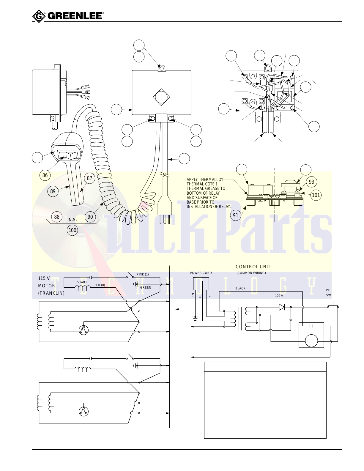
Service
Motor Control Unit
TO MOTOR
GRN-GRD
BLK-L1
WHT-L2
980 Hydraulic P ower Pump
97A
98
GREENLEE
ELECTRONIC MOTOR CONTROL
BLACK WIRE
MOTOR L1
MOTOR GROUND
G
96
97
98
97
98
92
WHITE WIRE
PENDANT CORD
93
91
BLACK WIRE
94
POWER CORD
94
WHITE WIRE
MOTOR L2
95
BLACK WIRE L1
GREEN WIRE
101
UNDER PC BOARD
WHITE WIRE L2
85
86
89
115 V
MOTOR
(FRANKLIN)
220 V
MOTOR
(FRANKLIN)
88
N.S.
100
START
2
3
START
2
3
87
90
RED (8)
BLACK (2)
BLUE (4)
VIOLET (9)
BROWN (10)
1
ORANGE (5)
RED (8)
BLACK (2)
BLUE (4)
VIOLET (9)
BROWN (10)
1
ORANGE (5)
PINK (1)
GREEN
4
3
2
1
PINK (1)
GREEN
4
3
2
1
WHITE
BLACK
WHITE
BLACK
99
APPLY THERMALLOY
THERMAL COTE 1
THERMAL GREASE TO
BOTTOM OF RELAY
AND SURFACE OF
BASE PRIOR TO
INSTALLATION OF RELAY.
POWER CORD
GREEN
WHITE
GREEN
WHITE
BLACK
92
95
93
91
CONTROL UNIT
(COMMON WIRING)
BLACK
100 V
BLACK
4
1
115 V 8 V
@ 1.12 VA
8
6
MOTOR WIRE CHART
FRANKLIN ELEC. GENERAL ELEC.
BROWN (10) PURPLE (P1)
VIOLET (9) BROWN (P2)
PINK (1) BLACK (T5)
ORANGE (5) ORANGE (T3)
BLACK (2) YELLOW (T4)
RED (8) RED (J10)
BLUE (4) WHITE (T2)
1 AMP
7
16 VDC
47yF
5
BLACK
240 VAC
+
45 AMP
R1
4
3-32 VDC
101
PENDANT
SWITCH
WHITE
2
+3
Greenlee Textron Inc. / Subsidiary of Textron Inc.
19
4455 Boeing Dr., Rockford, IL 61109-2988 815/397-7070
Page 3
Service (cont’d)
980 Hydraulic P ower Pump
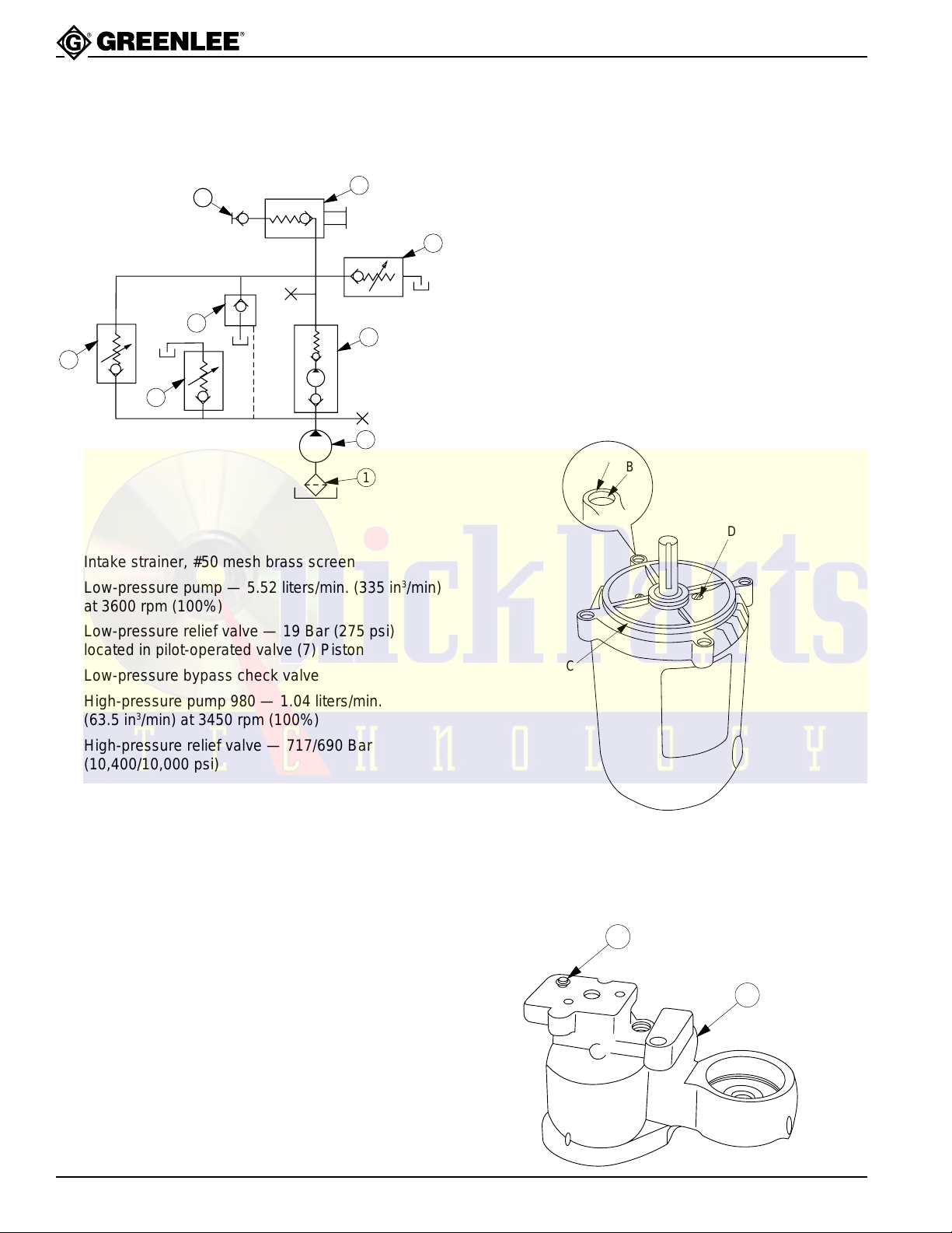
Hydraulic Schematic
9
7
4
3
8
5
2
1
(1) Intake strainer, #50 mesh brass screen
(2) Low-pressure pump — 5.52 liters/min. (335 in
3
/min)
at 3600 rpm (100%)
(3) Low-pressure relief valve — 19 Bar (275 psi)
located in pilot-operated valve (7) Piston
(4) Low-pressure bypass check valve
980
(5) High-pressure pump
— 1.04 liters/min.
(63.5 in3/min) at 3450 rpm (100%)
(6) High-pressure relief valve — 717/690 Bar
(10,400/10,000 psi)
(7) Pilot-operated directional control valve — 3 way,
2 position
(8) Manually operated check valve
(9) Female coupler half
Sealing Instructions for Assembly
Motor
If the motor has been disassembled, seal with a 3 mm
(1/8") bead of a silicone-based gasket/flange sealant,
such as Loctite
6
(A) To the mounting surface around the threads
(four locations)
®
587 Ultra Blue®, as follows:
(B) To the chamfer (four locations)
(C) Around the innermost machined circumference
of the mounting surface
Apply a 1.5 mm (1/16") bead of an RTV-type siliconebased sealant, such as Dow Corning 732™ Multipurpose
Sealant, as follows:
(D) Around the motor bearing screws (two locations)
Assemble immediately.
A
B
D
C
Driv-Lok Pin
Seal the Driv-Lok pin (73) to the pump block (84) with
a 1.5 mm (1/16") bead of an RTV-type silicone-based
sealant, such as Dow Corning 732™ Multipurpose
Sealant or equivalent.
Greenlee Textron Inc. / Subsidiary of Textron Inc.
20
73
84
4455 Boeing Dr., Rockford, IL 61109-2988 815/397-7070
Page 4
Repairs
45°
STOP
CLOSED
STOP
OPEN
BALL OPEN
112.5
°
(.99 mm [.039"])
POSITION 2
SET POSITION #1
22.5 (REF.)
135°
Figure A3
8
980 Hydraulic P ower Pump
The following section and figures describe pertinent
details for refinishing ball seats and component
re-assembly and adjustments.
Motor Face Seal
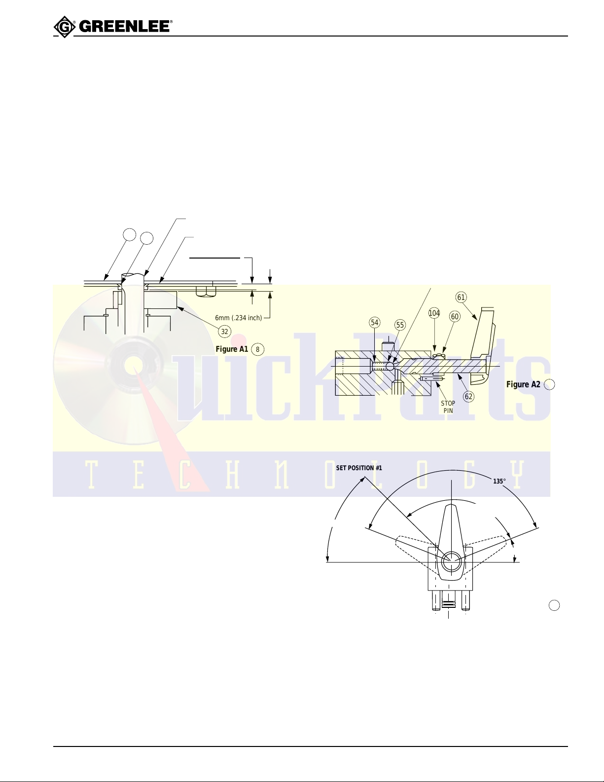
When reassembling the motor, refer to Figure A1 for the
face seal seating dimension. Also, refer to this figure for
setting the vertical position of counterweight (32).
MOTOR SHAFT
22
21
MOTOR FACE
4.6mm (.180 inch)
4.1mm (.160 inch)
6mm (.234 inch)
32
Figure A1
8
Manual Release/Automatic Release Valve
Handle Setting
Refer to Figures A2 and A3. Thread in the shaft (62) until
it just touches the check ball (55) (in its spring-loaded
closed position). Slide collar (104) on the shaft. Position
the handle (61) at the location “Position 1” (Figure A3),
with the other surface of the handle flush with the end of
the shaft. Lock in place. Rotate the handle to “Position 2”
(Figure A3). Slide the collar toward the valve body until
it contacts the 15.9 mm (5/8") diameter portion of the
control shaft. Rotate the lock collar clockwise until it
touches the stop pin, and lock in place.
When locking control handle and lock collar in place,
torque set screws tight to 2.8–3.4 N·m (25–30 inch-pounds).
7.938 mm (0.312") ø BALL SEAT
61
104
54
55
60
STOP
PIN
Figure A2
62
8
Greenlee Textron Inc. / Subsidiary of Textron Inc.
21
4455 Boeing Dr., Rockford, IL 61109-2988 815/397-7070
Page 5
Repairs (cont’d)
980 Hydraulic P ower Pump
Low Pressure Relief Setting
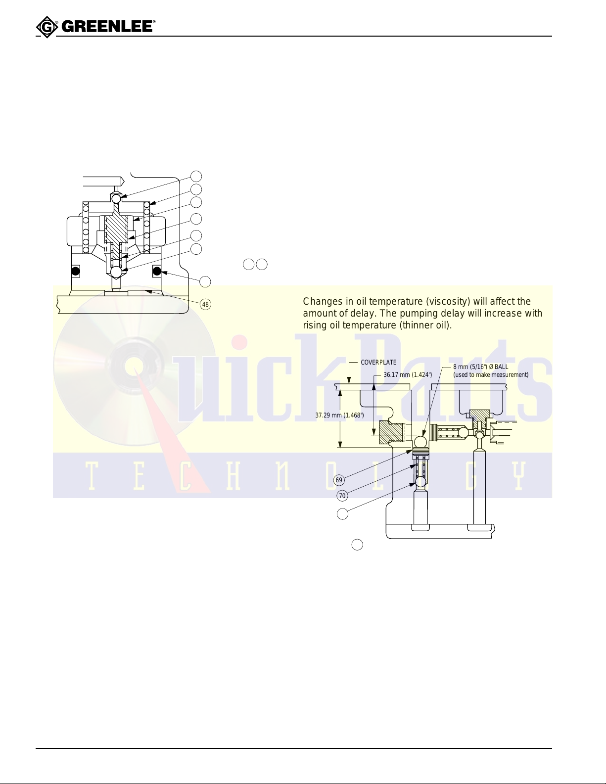
Refer to Figure A4. Lightly bottom the stem (44) on the
ball (46). Then, back out the stem 3-1/2 turns. Tighten
nut (43). The resulting pressure setting should be
approximately 19 Bar (280 psi).
42
47
43
44
45
46
3
Figure A4
49
48
7
Low-Pressure Bypass Check Pressure Adjustment
When properly set to the dimension shown in Figure A5,
the high pressure stage operation of the pump will be
delayed approximately one (1) second after the motor
starts. This delay is created by the closing time of the
pilot-operated valve.
Note: This dimension must be increased if ball
seat depth is increased by more than
.4 mm (1/64 inch).
Increasing the bypass pressure (CW rotation of adjusting
screw—increase of set dimension) will shorten delay. If
delay becomes too short, the motor will not restart when
high pressure is held in the line. The motor should restart
with a maximum required off time of 1/2 to 1 second.
Decreasing the bypass pressure (CCW rotation of
adjusting screw) will increase delay. The pilot-operated
valve will not close if pressure is set too low.
Changes in oil temperature (viscosity) will affect the
amount of delay. The pumping delay will increase with
rising oil temperature (thinner oil).
COVERPLATE
36.17 mm (1.424")
8 mm (5/16") Ø BALL
(used to make measurement)
37.29 mm (1.468")
69
70
71
Figure A5
4
Greenlee Textron Inc. / Subsidiary of Textron Inc.
22
4455 Boeing Dr., Rockford, IL 61109-2988 815/397-7070
Page 6
Repairs (cont’d)
L
3
Figure B2
7
3.175 mm (.125) Ø REAM
4.76 mm (.187") Ø BALL SEAT
(P.O. VALVE)
7.14 mm (.281") Ø DRILL
11.51 mm (.453") Ø DRILL
6.35 mm (.250") Ø BALL SEAT
(LO-P RELIEF VALVE)
4.76 mm (.187") Ø REAM
980 Hydraulic P ower Pump
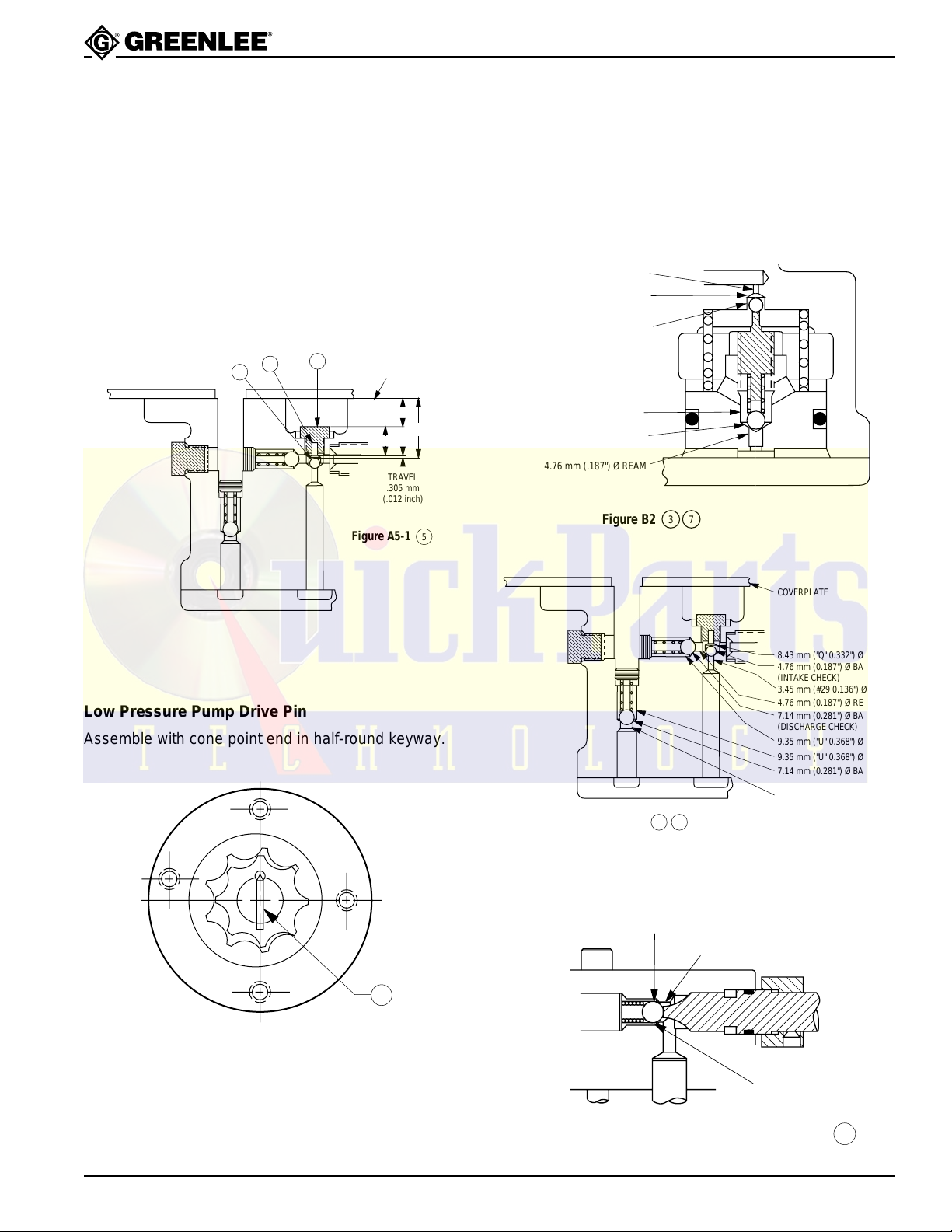
High-Pressure Inlet Check Ball Travel
The amount of allowable ball travel is critical to the
optimum high pressure output (flow rate). Refer to Figure
A5-1. Carefully and accurately measure (depth “mike”)
the “A” dimension (top of pump block to seated ball)
and “B” dimension (top of pump block to head of plug—
at center). Carefully and accurately set the “C” dimension
(overall length of assembled plug and pin) of a
new plug and pin equal to “A” minus “B” minus
.305 ± .050 mm (.012 ± .002 inches).
105
42
79
TOP OF
PUMP BLOCK
C
TRAVEL
.305 mm
(.012 inch)
Figure A5-1
B
A
5
Ball Seat Refinishing
Refer to Figures B2, B3, and B4 for the proper drill size
to refinish the conical seat and finish ream size. These
operations must be performed with the pump or valve
block properly held and using a drill press. Only a very
small amount of material should be removed.
Low Pressure Pump Drive Pin
Assemble with cone point end in half-round keyway.
Figure A6
78
4
Figure B3
5
7.94 mm (0.312") Ø BALL SEAT
(LINE CHECK VALVE)
7.14 mm (0.281") Ø REAM
COVERPLATE
8.43 mm ("Q" 0.332") Ø DRILL
4.76 mm (0.187") Ø BALL SEAT
(INTAKE CHECK)
3.45 mm (#29 0.136") Ø REAM
4.76 mm (0.187") Ø REAM
7.14 mm (0.281") Ø BALL SEAT
(DISCHARGE CHECK)
9.35 mm ("U" 0.368") Ø DRILL
9.35 mm ("U" 0.368") Ø DRILL
7.14 mm (0.281") Ø BALL SEAT
(BYPASS CHECK)
4.76 mm (0.187") Ø REAM
Greenlee Textron Inc. / Subsidiary of Textron Inc.
9.53 mm (0.375") Ø DRIL
Figure B4
23
4455 Boeing Dr., Rockford, IL 61109-2988 815/397-7070
8
Page 7
Exploded View
100
980 Hydraulic P ower Pump
87 89
86
85
90
88
31
8
99
Fig. A2
9
14
26
27
26
31
27
16
4
34
21
2
1
28
10
1
22
109
110
1
2 28
1
7
Serial
No.
6
19
1
2
3
15
2
1
1
1
7
12
Figs A1 & A5
18
Greenlee Textron Inc. / Subsidiary of Textron Inc.
Fig A4
23
13
32
33
17
11
13
12
35
24
24
25
4455 Boeing Dr., Rockford, IL 61109-2988 815/397-7070
24
25
Page 8
980 Hydraulic P ower Pump
Exploded View—Pump Block
65
52
54
9
53
55
59
66
64
63
62
104
61
34
32
36
33
58
56
69
70
71
6
See Driv-Lok Pin under
Sealing Instructions
for Assembly in the
Service Section.
73
5
T orque T able
1 1.13 - 1.35 N•m 10 - 12 inch-pounds
2 2.8 - 3.4 N•m 25 - 30 inch-pounds
3 110 N•m 80 foot-pounds
4 27 N•m 20 foot-pounds
5 34 N•m 25 foot-pounds
6 68 N•m 50 foot-pounds
72
68
107
57
79
105
69
112
4
70
44
45
46
48
71
60
106
42
114
41
37
80
81
102
7
82
83
39
78
2
38
2
40
77
103
76
75
3
84
42
43
2
7
47
503 4369.6
Hydraulic Repair Kit
503 5464.7
Release Knob Retrofit Kit
Greenlee Textron Inc. / Subsidiary of Textron Inc.
49
50
7
25
4455 Boeing Dr., Rockford, IL 61109-2988 815/397-7070
7
Page 9
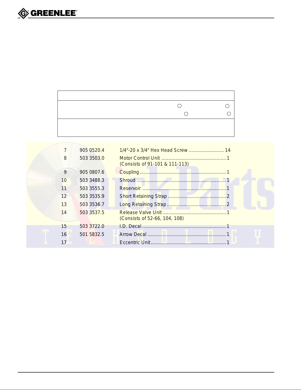
Parts List
980 Hydraulic P ower Pump
KEY PART NO. DESCRIPTION QTY.
1 503 3518.9 Carrying Handle...................................................2
2 905 3709.2 1/4"-20 x 1-1/4" Hex Head Screw........................8
3 503 3962.1 Decal....................................................................1
4 918 6314.7 Motor, 115 VAC, 1-1/2 HP...................................1
GE Motor 5KC48NG848X
FE Motor 1103007483
SERVICE PARTS: GE FE
Greenlee No. 918 5349.4
Capacitor Manufacturer No. 8753704AX16
1
1
918 6548.4
275463-103
Greenlee No. 918 5353.2 918 6549.2
Cover, Cap Manufacturer No. 111B276AA1 290312-101
6 503 2661.9 Fill-Vent Plug .......................................................1
7 905 0520.4 1/4"-20 x 3/4" Hex Head Screw..........................14
8 503 3503.0 Motor Control Unit ...............................................1
(Consists of 91-101 & 111-113)
9 905 0807.6 Coupling...............................................................1
10 503 3488.3 Shroud .................................................................1
11 503 3555.3 Reservoir .............................................................1
12 503 3535.9 Short Retaining Strap ..........................................2
13 503 3536.7 Long Retaining Strap...........................................2
14 503 3537.5 Release Valve Unit ..............................................1
(Consists of 52-66, 104, 108)
15 503 3722.0 I.D. Decal .............................................................1
16 501 5832.5 Arrow Decal .........................................................1
17 Eccentric Unit.......................................................1
(see Exploded View—Pump Block for breakdown)
18 Pump Block Unit ..................................................1
(see Exploded View—Pump Block for breakdown)
19 905 0530.1 Hex Hd. Cap Screw #3/8-16 x 1.00.....................3
*21 905 3682.7 Seal......................................................................1
22 503 3517.0 Cover Plate ..........................................................1
*23 503 2627.9 Cover Plate Gasket .............................................1
24 905 3829.3 Rubber Foot.........................................................4
25 905 1185.9 Screw, 1/4"-20 x 1/2" ...........................................4
26 905 1460.2 Self-Tapping Screw #10 x 3/8" ............................2
2
2
Greenlee Textron Inc. / Subsidiary of Textron Inc.
26
4455 Boeing Dr., Rockford, IL 61109-2988 815/397-7070
Page 10
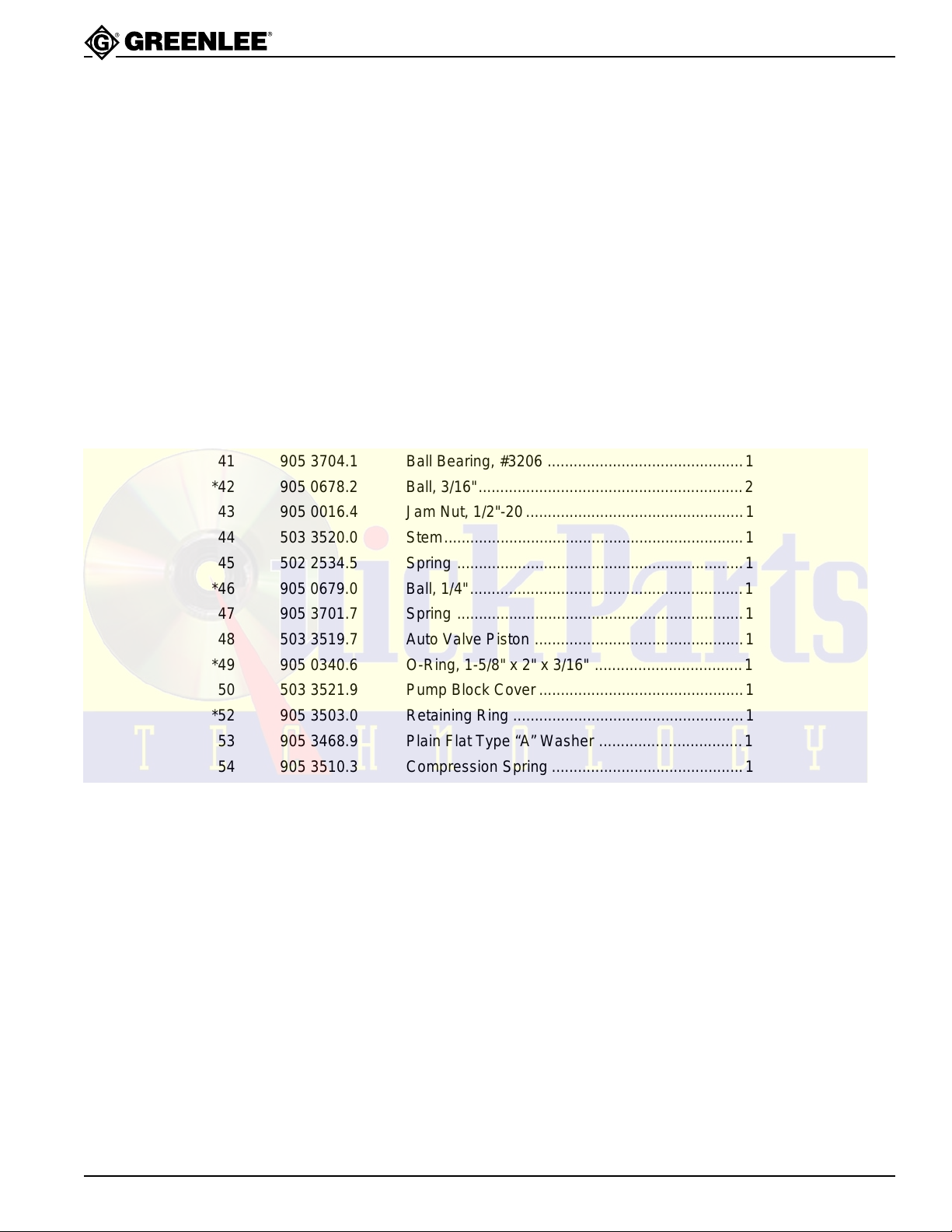
Parts List (cont’d)
KEY PART NO. DESCRIPTION QTY.
27 905 3468.9 #10 Flat Washer ..................................................2
28 905 2339.3 1/4" Flat Washer ..................................................4
31 503 9896.2 Mounting Strap ....................................................1
32 503 3527.8 Counterweight......................................................1
33 905 1269.3 Set Screw, 1/4"-20 x 1/4".....................................1
34 501 4557.6 Motor Shaft Key, 3/16" x 1-3/8" ...........................1
35 905 0533.6 Hex Hd. Cap Screw 3/8"-16 x 1.50......................1
36 905 3707.6 Retaining Ring .....................................................1
37 905 3758.0 Ball Bearing #1206 ..............................................1
38 503 3526.0 Eccentric Shaft.....................................................1
39 905 0699.5 Rollpin, 3/16" x 1" ................................................1
40 905 0791.6 Set Screw, #10-32 x 1/4".....................................1
41 905 3704.1 Ball Bearing, #3206 .............................................1
*42 905 0678.2 Ball, 3/16".............................................................2
43 905 0016.4 Jam Nut, 1/2"-20..................................................1
44 503 3520.0 Stem.....................................................................1
45 502 2534.5 Spring ..................................................................1
*46 905 0679.0 Ball, 1/4"...............................................................1
47 905 3701.7 Spring ..................................................................1
48 503 3519.7 Auto Valve Piston ................................................1
*49 905 0340.6 O-Ring, 1-5/8" x 2" x 3/16" ..................................1
50 503 3521.9 Pump Block Cover ...............................................1
*52 905 3503.0 Retaining Ring .....................................................1
53 905 3468.9 Plain Flat Type “A” Washer .................................1
54 905 3510.3 Compression Spring ............................................1
*55 905 0680.4 Ball, 5/16".............................................................1
56 503 2622.8 Coupling...............................................................1
*57 905 1290.1 Back-up Ring, 3/8" x 1/2" x 1/16" ........................2
*58 905 0168.3 O-Ring, 3/8" x 1/2" x 1/16"...................................2
*59 503 2626.0 Gasket .................................................................1
+60 905 1269.3 Set Screw, 1/4"-20 x .38......................................2
+61 503 4796.9 Release Valve Knob ............................................1
62 503 3541.3 Control Shaft........................................................1
*63 905 3827.7 Back-up Ring, 1/2" x 5/8".....................................1
980 Hydraulic P ower Pump
Greenlee Textron Inc. / Subsidiary of Textron Inc.
27
4455 Boeing Dr., Rockford, IL 61109-2988 815/397-7070
Page 11
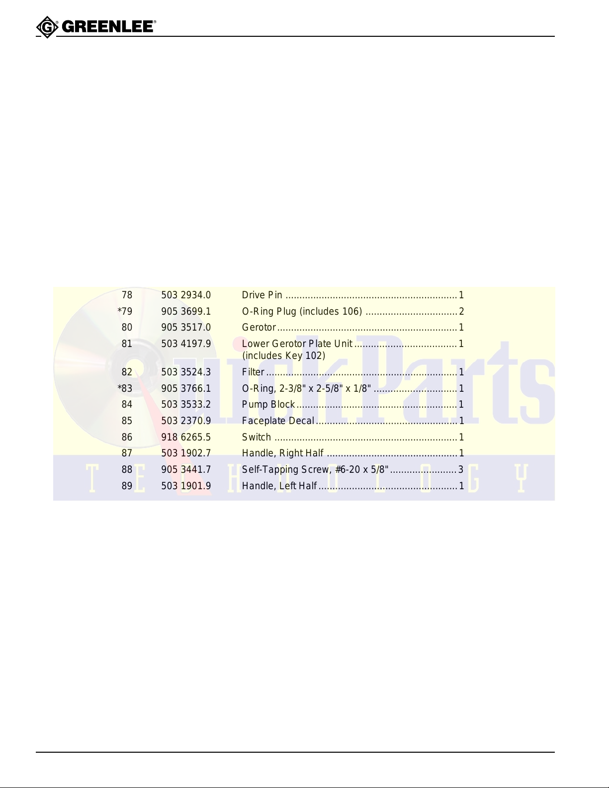
Parts List (cont’d)
KEY PART NO. DESCRIPTION QTY.
*64 905 0912.9 O-Ring, 1/2" x 5/8" x 1/16"...................................1
65 905 3496.4 Cap Screw, 5/16"-18 x 2.50.................................2
66 503 2623.6 Release Valve Body ............................................1
*68 905 3698.3 O-Ring Plug (includes 107) .................................1
69 905 3712.2 Jam Screw, 7/16".................................................2
70 905 3702.5 Spring ..................................................................2
*71 905 0436.4 Ball, 9/32".............................................................2
72 500 6067.8 High Pressure Relief Valve..................................1
73 905 3706.8 Type “D” Driv-Lok Pin, 1/4" x 1/2" .......................1
75 503 3530.8 High Pressure Bushing........................................1
76 503 3528.6 High Pressure Piston...........................................1
77 503 3525.1 Drive Shaft ...........................................................1
78 503 2934.0 Drive Pin ..............................................................1
*79 905 3699.1 O-Ring Plug (includes 106) .................................2
80 905 3517.0 Gerotor.................................................................1
81 503 4197.9 Lower Gerotor Plate Unit .....................................1
82 503 3524.3 Filter.....................................................................1
*83 905 3766.1 O-Ring, 2-3/8" x 2-5/8" x 1/8" ..............................1
84 503 3533.2 Pump Block..........................................................1
85 503 2370.9 Faceplate Decal...................................................1
86 918 6265.5 Switch ..................................................................1
87 503 1902.7 Handle, Right Half ...............................................1
88 905 3441.7 Self-Tapping Screw, #6-20 x 5/8"........................3
89 503 1901.9 Handle, Left Half..................................................1
90 503 2362.8 Cord ..................................................................... 1
91 503 3491.3 Motor Control Base..............................................1
92 918 6292.2 Relay....................................................................1
93 905 3840.4 Self-Tapping Screw, #6-32 x 5/16"......................6
94 905 3695.9 Pan Head Type C Screw, #6-32 x 1/4" ...............2
95 503 3733.5 Transformer Unit..................................................1
96 503 3492.1 Motor Control Cover ............................................1
97 905 3580.7 Pan Head Mach. Screw, #6-32 x 5/8" .................2
97A 905 0430.5 Pan Head Mach. Screw, #6-32 x 3/8" .................1
980 Hydraulic P ower Pump
(includes Key 102)
Greenlee Textron Inc. / Subsidiary of Textron Inc.
28
4455 Boeing Dr., Rockford, IL 61109-2988 815/397-7070
Page 12
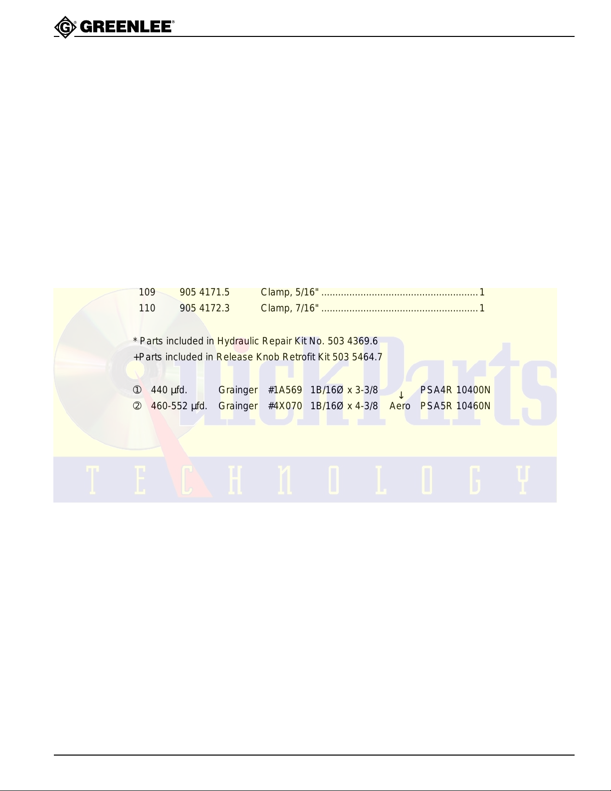
Parts List (cont’d)
KEY PART NO. DESCRIPTION QTY.
98 905 0632.4 Hex Nut, #6–32 ....................................................3
99 918 6487.9 96" Long Cord......................................................1
100 503 2363.6 Pendant Switch Unit ............................................1
101 905 3831.5 Nylon Spacer, .150 ID x 5/16" OD x .050 ............4
102 905 3839.0 Bearing, Bronze ...................................................1
103 905 3320.8 Bearing, Bronze, 1/2" x 5/8" x 1/2" ......................1
+104 503.4886.8 Shaft Stop Collar .................................................1
*105 905 3816.1 Pin, 1/8" x 1/4" Driv-Lok.......................................1
106 905 3878.1 O-Ring .................................................................2
107 905 3880.3 O-Ring .................................................................1
+108 905 0078.4 Roll Pin, .187 Dia. x 3/4" Long.............................1
109 905 4171.5 Clamp, 5/16" ........................................................1
110 905 4172.3 Clamp, 7/16" ........................................................1
980 Hydraulic P ower Pump
(Consists of 85-90)
* Parts included in Hydraulic Repair Kit No. 503 4369.6
+Parts included in Release Knob Retrofit Kit 503 5464.7
➀ 440 µfd. Grainger #1A569 1B/16Ø x 3-3/8
➁ 460-552 µfd. Grainger #4X070 1B/16Ø x 4-3/8 Aero PSA5R 10460N
PSA4R 10400N
↓
Greenlee Textron Inc. / Subsidiary of Textron Inc.
29
4455 Boeing Dr., Rockford, IL 61109-2988 815/397-7070
 Loading...