

Page 1
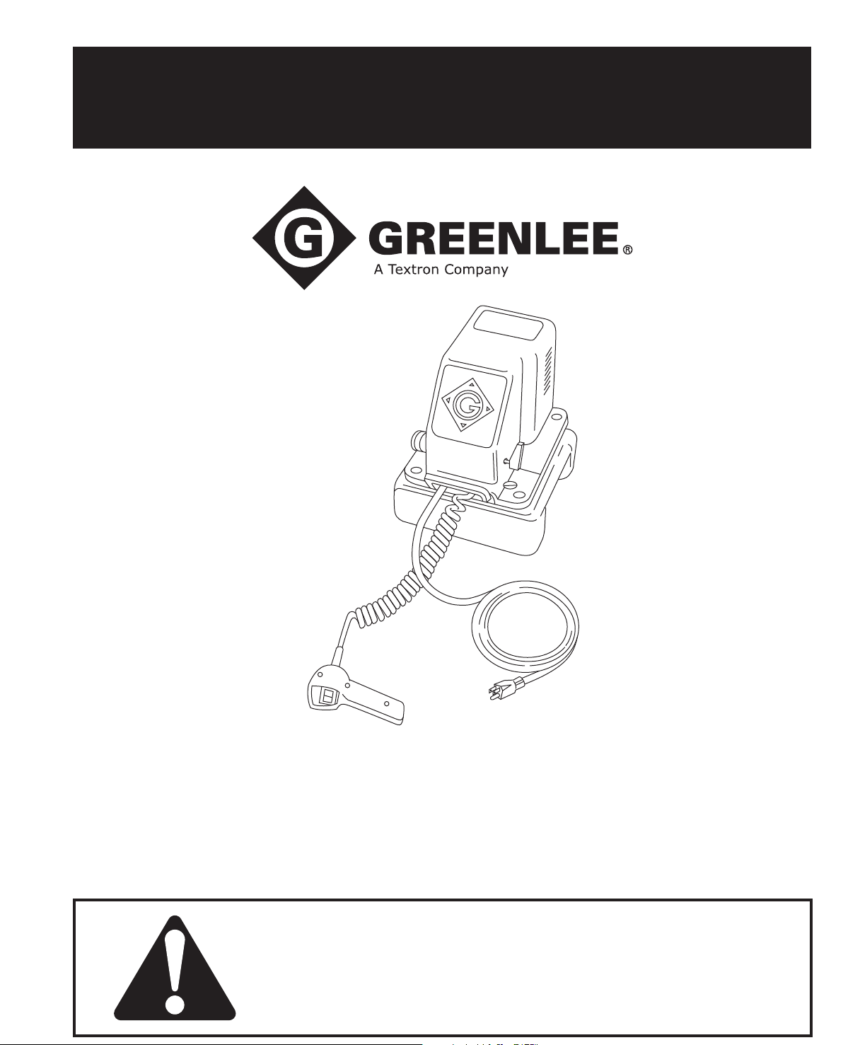
INSTRUCTION MANUAL
975
Hydraulic Power Pump
Serial Code TZ
Read and understand all of the instructions and
safety information in this manual before operating
or servicing this tool.
Page 2
975 Hydraulic Power Pump
Table of Contents
Description .................................................................... 2
Safety ............................................................................ 2
Purpose of this Manual ................................................. 2
Important Safety Information ..................................... 3-4
Specications ................................................................ 5
Setup
Hydraulic Connection ................................................ 6
Electrical Connection/Grounding Instructions ........... 6
Operation ....................................................................... 7
Maintenance ............................................................... 8-9
Troubleshooting ...................................................... 10-15
Service ................................................................... 16-18
Repairs ................................................................... 19-21
Exploded Views ...................................................... 22-23
Parts List ................................................................ 24-26
Description
Greenlee 975 Hydraulic Power Pump is an electrically
powered two-stage pump that develops a maximum of
700 bar (10,000 psi). This pump is intended to provide
hydraulic power for an accessory with a single-acting
ram such as a Greenlee conduit bender or cable cutter.
This pump has a factory-set internal pressure relief
valve.
Fill unit with hydraulic oil before operating pump.
Failure to ll unit with oil will result in
damage to the pump
Safety
Safety is essential in the use and maintenance of
Greenlee tools and equipment. This instruction manual
and any markings on the tool provide information for
avoiding hazards and unsafe practices related to the
use of this tool. Observe all of the safety information
provided.
Purpose of this Manual
This manual is intended to familiarize all personnel with
the safe operation and maintenance procedures for the
following Greenlee 975 (Serial Code TZ).
Keep this manual available to all personnel.
Replacement manuals are available upon request at no
charge at www.greenlee.com.
All specications are nominal and may change as design
improvements occur. Greenlee Textron Inc. shall not be liable for
damages resulting from misapplication or misuse of its products.
732 is a trademark of Dow Corning.
Loctite and Ultra Blue are registered trademarks of Loctite
Corporation.
Mobil DTE is a registered trademark of Mobil Oil Corporation.
KEEP THIS MANUAL
Find Quality Products Online at: [email protected]
www.GlobalTestSupply.com
Page 3
IMPORTANT SAFETY INFORMATION
SAFETY
ALERT
SYMBOL
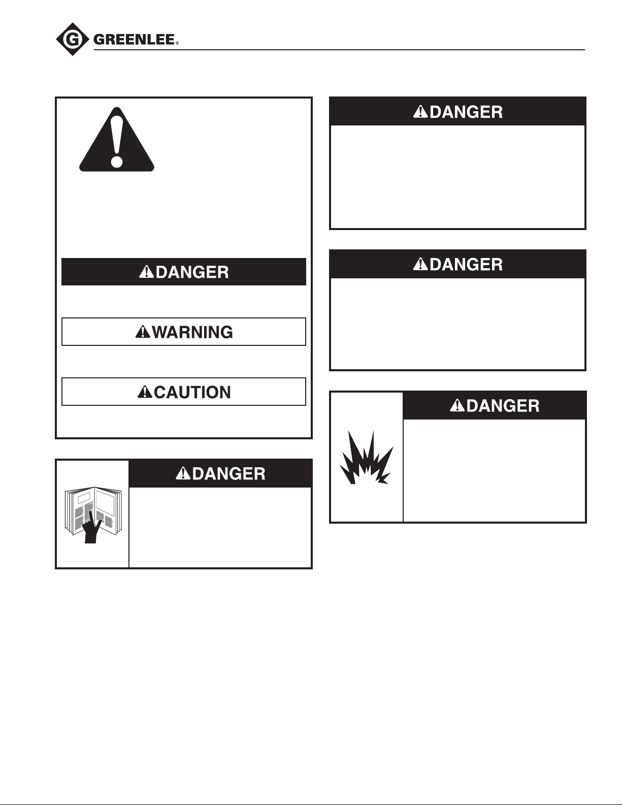
This symbol is used to call your attention to hazards
or unsafe practices which could result in an injury or
property damage. The signal word, dened below,
indicates the severity of the hazard. The message
after the signal word provides information for preventing or avoiding the hazard.
975 Hydraulic Power Pump
Do not connect the pump to any system or system
component other than those supplied by Greenlee.
Other manufacturer’s components may not withstand
the maximum pressure and may fail. Nearby personnel can be injured by ying components and hydraulic
oil.
Failure to observe this warning will result in severe
injury or death.
Immediate hazards which, if not avoided, WILL result
in severe injury or death.
Hazards which, if not avoided, COULD result in
severe injury or death.
Hazards or unsafe practices which, if not avoided,
MAY result in injury or property damage.
Read and understand all of the
instructions and safety information
in this manual before operating or
servicing this tool.
Failure to observe this warning will
result in severe injury or death.
Do not alter the internal high-pressure relief valve
setting. Altering this setting will change the maximum
pressure the pump can develop, which can cause a
component failure. Nearby personnel can be injured
by ying components and hydraulic oil.
Failure to observe this warning will result in severe
injury or death.
Do not use this pump in a hazardous
environment. Hazards include am-
mable liquids, gases, or other materials. Using this pump in a hazardous
environment can result in a re or
explosion.
Failure to observe these warnings will
result in severe injury or death.
Find Quality Products Online at: [email protected]
www.GlobalTestSupply.com
Page 4
975 Hydraulic Power Pump
IMPORTANT SAFETY INFORMATION
Electric shock hazard:
• Do not expose power tools to rain.
• Do not immerse the pendant switch
in water or other liquid.
Failure to observe these warnings can
result in severe injury or death.
Skin injection hazard:
High pressure oil easily punctures
skin causing serious injury, gangrene,
or death. If injured, seek medical help
immediately to remove oil.
Do not use ngers or hands to
•
check for leaks.
Depressurize hydraulic system
•
before servicing or disconnecting
the hose.
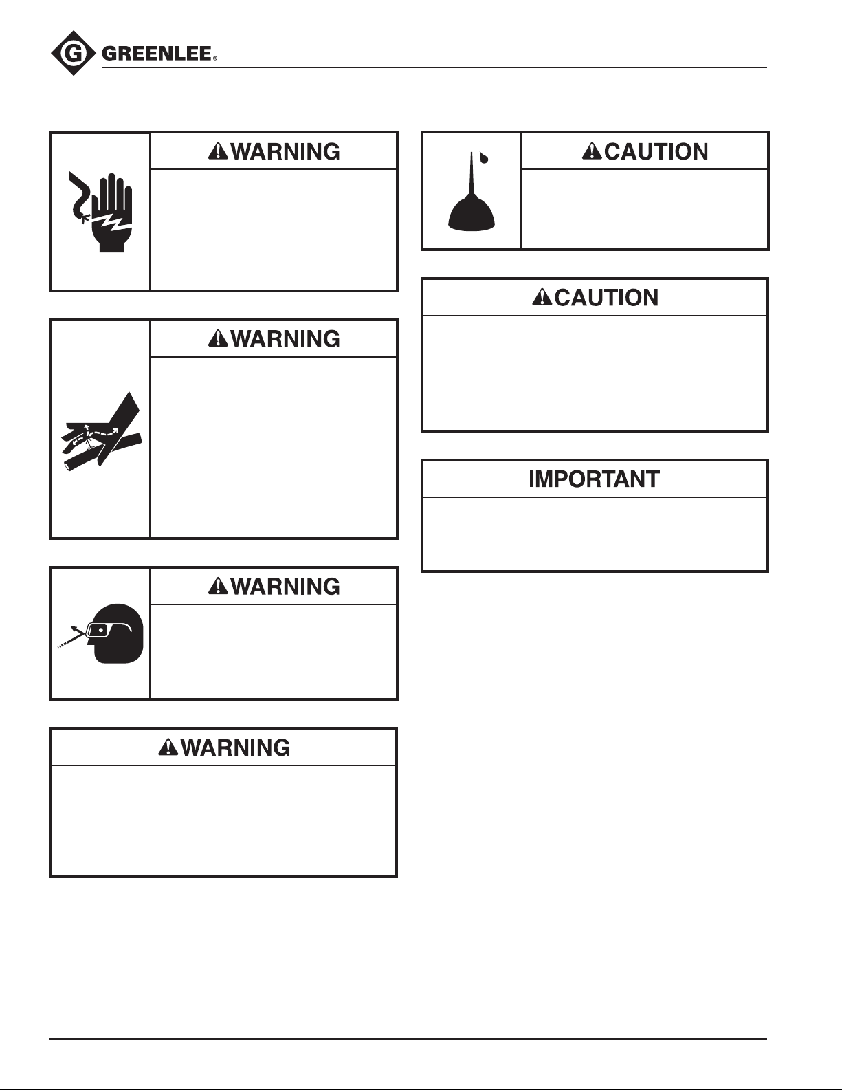
Fill unit with hydraulic oil before operating pump.
Failure to ll unit with oil will result in
damage to the pump
• The pump is heavy and requires two persons to lift.
Improper lifting can result in injury.
• Do not use hose or cord to pull, lift, or carry the
equipment. Misuse will damage the hose or cord.
Failure to observe these precautions can result in
injury or property damage.
Make sure all hose ttings are properly seated before
starting the pump. Incomplete connections may not
allow the accessory’s ram to retract after the hydraulic operation is nished.
Wear eye protection when using this
tool.
Failure to wear eye protection can
result in serious eye injury from ying
debris or hydraulic oil.
Inspect pump, hoses, couplers, and ttings for wear
or damage. Replace worn, damaged or missing components with Greenlee replacement parts. Worn or
damaged components can fail, resulting in injury.
Failure to observe this warning can result in severe
injury or death.
Keep all decals clean and legible, and replace
Note:
when necessary.
Find Quality Products Online at: [email protected]
www.GlobalTestSupply.com
Page 5

Specifications
Motor
Voltage ........................................................................................................ 120 VAC
Frequency ........................................................................................................ 60 Hz
Current .......................................................................................................... 9 amps
Power .......................................................................................................1080 watts
Revolutions per minute ..................................................................................... 3600
Pump Output
Power ........................................................................................... 373 watts (1/2 hp)
Hydraulic pressure (maximum) ...................................................700 bar (10,000 psi)
(pressure relief valve setting)
Hydraulic Fluid Capacity*
Full ................................................................................................5.7 liters (6 quarts)
Usable ..........................................................................................2.8 liters (3 quarts)
Hydraulic Fluid Specifications (Mobil DTE
Viscosity ........................................................... 30 cSt at 40 °C (150 SSU at 100 °F)
Viscosity Index .................................................................................................... 145
Pour Point .......................................................................................... -40 °F (-40 °C)
975 Hydraulic Power Pump
®
13M)
6 cSt at 100 °C (46 SSU AT 210 °F)
Typical Performance
Pressure Volume
0 .........................................................................................4.9 liter/min (300 in3/min)
6.9 bar (100 psi) .................................................................3.6 liter/min (225 in3/min)
345 bar (5000 psi) ..............................................................0.31 liter/min (19 in3/min)
552 bar (8000 psi) ..............................................................0.29 liter/min (18 in3/min)
Dimensions
Length ..................................................................................................305 mm (12")
Width .................................................................................................... 254 mm (10")
Height ................................................................................................ 394 mm (15.5")
Weight/Mass ..........................................................................................23 kg (51 lb)
Find Quality Products Online at: [email protected]
www.GlobalTestSupply.com
Page 6
Setup
975 Hydraulic Power Pump
Hydraulic Connection
1. Clean all couplers, threaded ttings, ports and the
area around all ports.
2. Remove any dust plugs from couplers.
3. Hand-tighten all couplings rmly (until all threads are
fully engaged). Do not use tools.
Electrical Connection
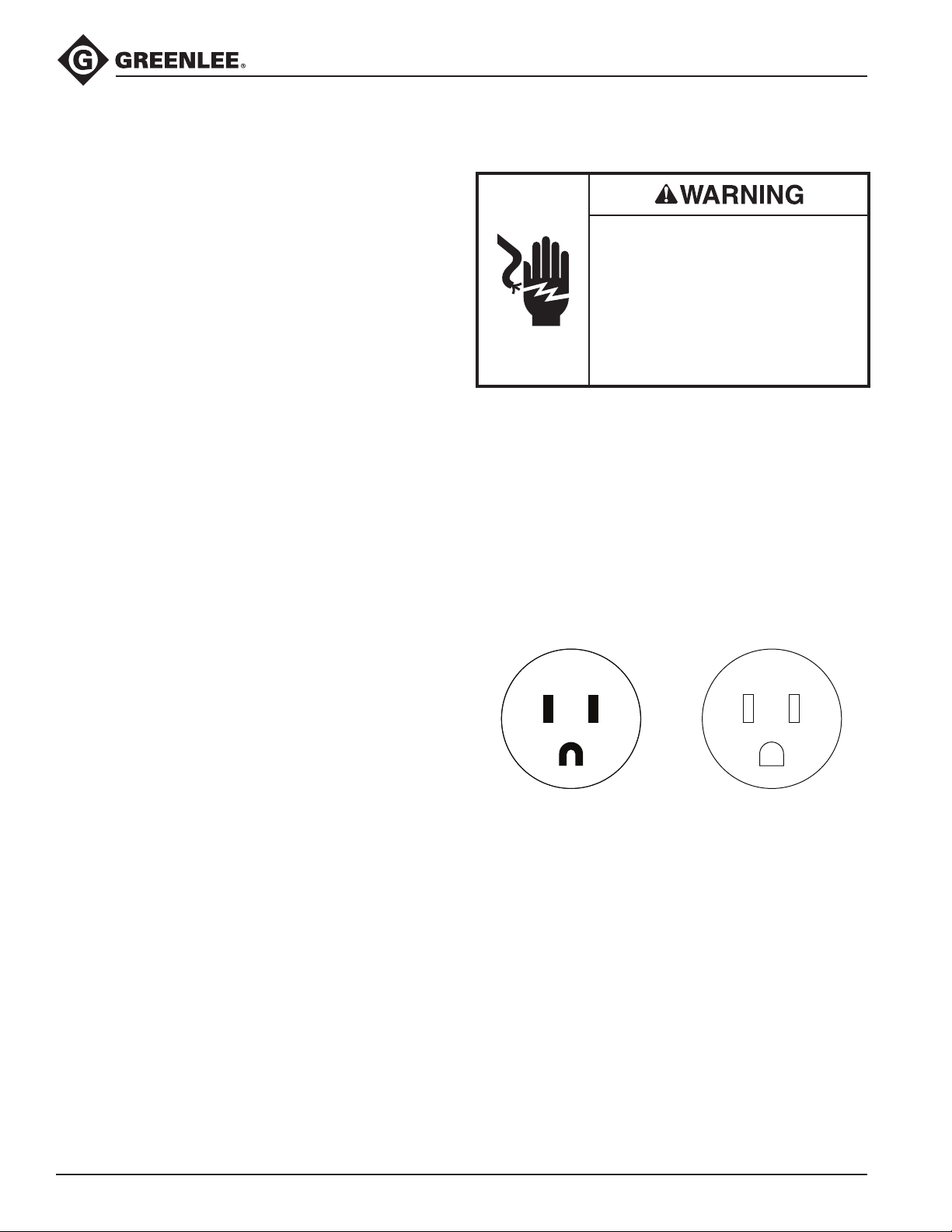
Electric shock hazard:
• Do not modify the plug provided
with the tool.
• Connect this tool to a grounded
receptacle on a 15-amp GFCI-
protected circuit.
Failure to observe these warnings can
result in severe injury or death.
This tool must be grounded. In the event of a malfunc-
tion or breakdown, an electrical ground provides a path
of least resistance for the electric current. This path of
least resistance is intended to reduce the risk of electric
shock.
This tool’s electric cord has a grounding conductor
and a grounding plug as shown. Do not modify the
plug. Connect the plug to a corresponding 15-amp
GFCI-protected receptacle that is properly installed
and grounded in accordance with all national and local
codes and ordinances. Do not use an adapter.
ReceptaclePlug
Extension Cord Specications:
Diameter ......................................... 1.5 mm2 (14 AWG)
Length .......................................... 30 meters (100 feet)
Use only three-wire extension cords. Use of an
inadequate extension cord will cause the motor to stall.
Find Quality Products Online at: [email protected]
www.GlobalTestSupply.com
Page 7
Operation
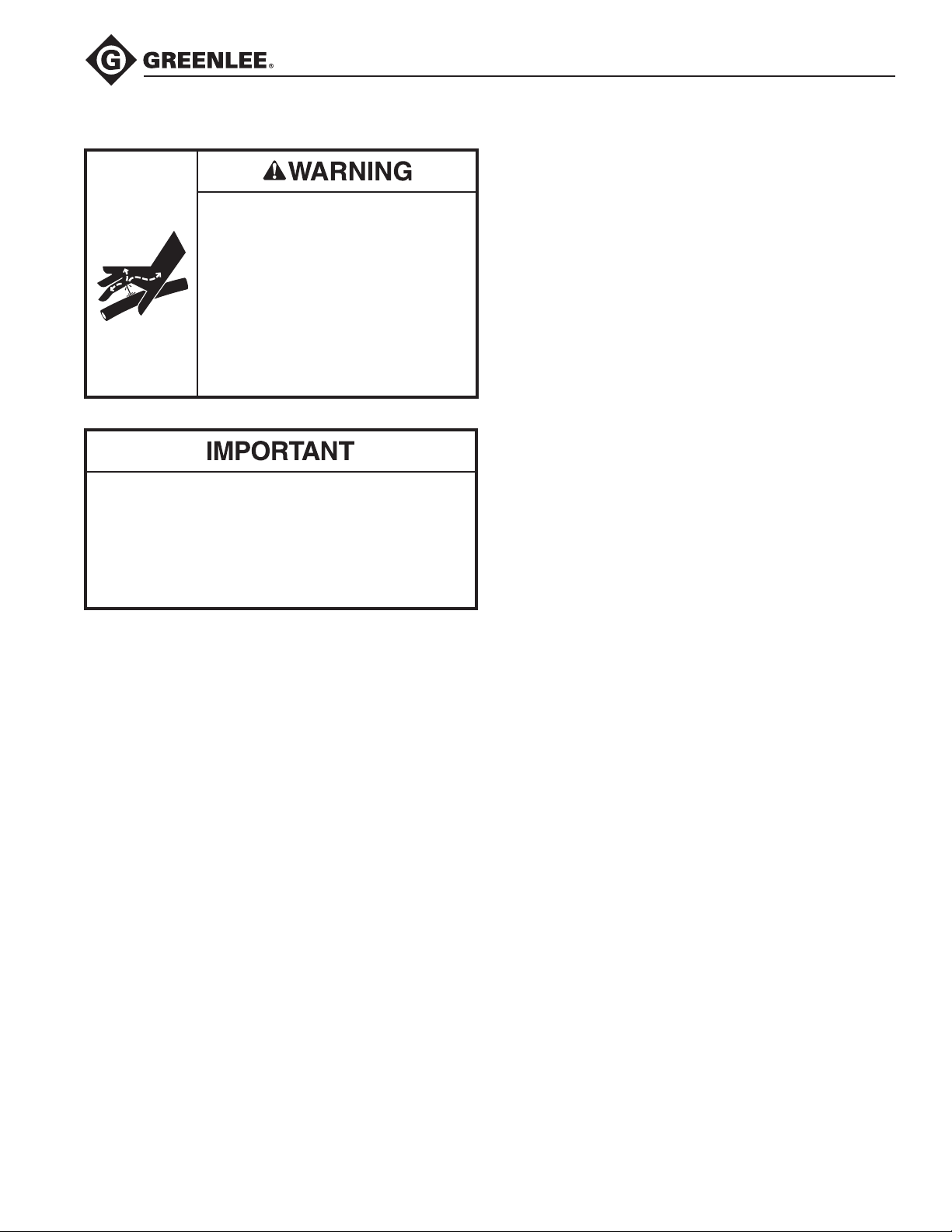
Skin injection hazard:
High pressure oil easily punctures
skin causing serious injury, gangrene,
or death. If injured, seek medical help
immediately to remove oil.
Do not use ngers or hands to
•
check for leaks.
Depressurize hydraulic system
•
before servicing or disconnecting
the hose.
Procedure for depressurizing the hydraulic system:
1. Disconnect the pump from the power source.
2. Rotate the release lever to AUTO RELEASE and
allow the ram to retract fully.
3. Disconnect the hose slowly to release any
trapped pressure.
975 Hydraulic Power Pump
To prevent leakage, this pump was shipped with
Note:
an unvented plug installed in the reservoir fill hole. This
plug must be replaced with the attached vented plug
(6) before use. Failure to replace the unvented plug will
cause poor performance.
Starting the motor without a tool attached to
Note:
the pump will cause the pump to immediately build an
internal pressure of 700 bar (10,000 psi). If this happens,
shut off the pump and turn the release valve to AUTO
RELEASE to release the hydraulic pressure.
Move release valve lever to the AUTO RELEASE
1.
position.
2. Check reservoir oil level. The oil level should be
within 25 mm (1 inch) of the top of the reservoir. If oil
level is too low, see Adding Oil in the Maintenance
section for instructions.
Place release valve lever in desired position:
3.
• AUTO RELEASE – ram will stop and then retract
when the hand switch or foot switch is released.
MANUAL RELEASE – ram will stop but will not
•
retract when the hand switch or foot switch is
released.
4. Press the hand switch or foot switch to advance
the hydraulic ram. When nished, release the hand
switch or foot switch.
If release valve lever is in the MANUAL
Note:
RELEASE position, the ram will not retract. To
retract ram, rotate the release valve lever to the
AUTO RELEASE position.
Find Quality Products Online at: [email protected]
www.GlobalTestSupply.com
Page 8
Maintenance
Procedure for depressurizing the hydraulic system:
1. Disconnect the pump from the power source.
2. Rotate the release lever to AUTO RELEASE and
allow the ram to retract fully.
3. Disconnect the hose slowly to release any
trapped pressure.
Every time the pump is used
• Check the oil reservoir level. The oil level should be
approximately 25 mm (1 inch) from the top of the reservoir. If the oil level is low, see Adding Oil.
Examine the condition of the hose, connectors, and
•
O-rings for deterioration, wear, or other damage.
Replace any missing or damaged components.
Check the condition of all electrical cords, plugs, and
•
connectors.
• Listen for unusual noises and observe the operation
of the pump for changes in performance. Either situation may indicate that maintenance or repairs are
necessary.
Periodically
Examine the hydraulic oil for changes in color
•
or viscosity, and the presence of dirt or other
contamination.
Occasionally check oil temperature after pump is
•
operated. The recommended operating temperature is
38 °C to 50 °C (100 °F to 125 °F).
975 Hydraulic Power Pump
Oil Condition
Visual inspection of the oil may be used as a guide
to determine the need to replace the oil. A change in
appearance, such as darkening or thickening, will indi-
cate a need for replacement. The continued use of oil
after it should be replaced will cause accelerated wear
of system components and will void the warranty.
Adding Oil
Do not use brake uid. Brake uid will ruin the seals.
1. Place control lever in AUTO RELEASE position.
2. Unplug the electrical cord from the power source.
3. Thoroughly clean the area around the ll hole.
4. Remove the vented reservoir plug.
5. Use Greenlee hydraulic uid or an equivalent highgrade light hydraulic oil. See the “Parts List” section
of this manual for Greenlee hydraulic oil specication and Greenlee part number.
Pour the oil through a clean funnel with lter screen.
6.
7. Add oil until oil level is 25 mm (1 inch) from the top
of the reservoir cover.
Cleaning
• Periodically clean the exterior of the pump and
motor. Use a vacuum cleaner to clean the ventilation
openings.
Clean the area around the reservoir vent, and be sure
•
the vent breather hole is open.
• Keep all hose connections clean and use protective
caps or plugs when couplers are not in use.
Find Quality Products Online at: [email protected]
www.GlobalTestSupply.com
Page 9
Maintenance (cont’d)
975 Hydraulic Power Pump
Purging (Bleeding) Air
When purging air from the system:
• Do not advance the ram more than 3/4 of its stroke.
Overextending the ram will allow hydraulic uid
to leak out, and the ram may damage the O-rings
when it retracts.
Do not restrict the ram travel to run the pump up
•
to full pressure (commonly called dead heading the
pump).
Failure to observe these precautions can result in
injury or property damage.
Erratic performance may indicate air in the hydraulic
system.
Remove the ram from the accessory (conduit
1.
bender frame, cable cutter, etc.).
2. If possible, position the pump so that it is located
higher than the ram. This will allow air to travel up
the hydraulic hose to the pump reservoir.
Place the ram in a vertical position with the hose
3.
coupler upward.
4. Rotate the control lever counterclockwise (to
MANUAL RELEASE).
Start the pump and, using the ram scale as a refer-
5.
ence, advance the ram 3/4 of its stroke. Stop the
pump. Do not overextend the ram!
6. Rotate the control lever clockwise (to AUTO
RELEASE). The ram will retract, forcing any air out
through the hose, into the pump reservoir, and
through the vented plug.
Check the oil lever of the reservoir. Add oil if
7.
necessary.
Draining and Flushing the System
Note: Thoroughly clean the pump exterior before
removing the reservoir.
Remove the reservoir cover screws.
1.
2. Remove the pump system from the reservoir.
Note: Be careful not to damage the cover gasket,
inlet strainer or relief valve when removing the
pump.
Clean the interior of the reservoir and ll with clean
3.
kerosene. Do not use solvents. Rinse the inlet
strainer.
4. Place the pump system into the reservoir and
replace the four cover screws.
Connect a hose to the pump as usual. Insert the
5.
other end of the hose into the pump reservoir at ll
hole.
Run the pump for several minutes. While the
6.
pump is running, rotate the control lever between
MANUAL RELEASE and AUTO RELEASE several
times. Start and stop the pump several times to
cycle the pilot-operated valve.
Remove the hose and remove the pump assembly
7.
from the reservoir. Drain and clean the reservoir inte-
rior. Allow the reservoir to dry. Drain the hose.
Reassemble the pump system.
8.
9. Rell reservoir as instructed under the Adding Oil
instructions in this section.
Motor Maintenance
Disconnect the pump from the power source before
servicing or cleaning the motor. The exposed motor
bearings and shaft should be cleaned periodically.
Lubrication
Lubricate the motor according the motor manufacturer’s
instructions, which are on the nameplate or the terminal
box cover.
Find Quality Products Online at: [email protected]
www.GlobalTestSupply.com
Page 10
Troubleshooting—Hydraulic Pump
975 Hydraulic Power Pump
Repair work must be done by qualied personnel famil-
iar with this equipment.
If possible, use a hand pump to apply back pressure
when checking for leaks.
Problem Probable Cause Probable Remedy
Motor will not start. No power to motor. Plug electric cord in to a properly
Motor is damaged or worn out. Replace motor.
Motor will not start under load. Voltage supplied to motor is too low. Unplug cord and check power
How to use this table: If your hydraulic pump does not
operate properly, nd the description of the problem
under the “Problem” column. Read the Probable Cause
and the Probable Remedy. Begin with solution listed
rst, and proceed through all of the solutions until the
problem is solved. Where repairs are necessary, see the
appropriate schematic and item listed in the “Probable
Remedy” column.
rated power source. Unplug cord
and inspect the contacts. Clean
contacts if necessary.
Replace the electric cord.
Replace switch cord or ON/OFF
switch.
source with a voltmeter. The voltage
should be 120 VAC (+/– 10%).
Motor starts, but stops when it
encounters a load.
Current rating of extension cord is
too low.
Pilot-operated valve will not open,
will not open fully, or opens too
slowly.
Voltage supplied to motor is too low. Unplug cord and check power
Current rating of extension cord is
too low.
Motor is overheated. Let motor cool. Do not run motor
Misalignment of the motor shaft and
low pressure pump drive shaft.
The counterweight needs
adjustment.
See the extension cord specications under Electrical Connection in
the Setup section of this manual.
See “Troubleshooting—PilotOperated Valve” at the end of this
troubleshooting section.
source with a voltmeter. The voltage
should be 120 VAC (+/– 10%).
See the extension cord specications under Electrical Connection in
the Setup section of this manual.
continuously in a hot environment.
Replace reservoir cover plate (22).
See Motor Face Seal, Figure
A1, for the correct setting of the
counterweight.
Motor is damaged or worn out. Replace motor.
Find Quality Products Online at: [email protected]
www.GlobalTestSupply.com
Page 11
975 Hydraulic Power Pump
Troubleshooting—Hydraulic Pump (cont’d)
Problem Probable Cause Probable Remedy
Ram will not advance.
Ram advances slowly.
Ram will not advance completely.
Low-pressure system has a partial or
complete failure.
Unvented plug has not been
replaced.
Oil level is too low. Add oil per instructions in the
Wrong oil viscosity. Replace oil with the type recom-
Oil is dirty. Replace oil with the type recom-
Oil is cold. Preheat oil. Without an acces-
The intake strainer is dirty or
clogged.
See Hydraulic Schematic (1,3,7)
and refer to Figure A4 in the Repairs
section of this manual.
Remove the unvented plug and
install the vented plug.
Maintenance and Service section of
this manual.
mended in the Specications section
of this manual.
mended in the Specications section
of this manual.
sory connected to the coupler, run
the pump to build pressure, then
release. Repeat until oil is warm.
Remove the strainer and clean with
kerosene.
Motor rotates in the wrong direction. Correct the motor wiring. See the
Motor Control, Schematic Diagram
in the Motor Control Unit section of
this manual.
Low-pressure relief valve is dirty or is
set incorrectly.
Broken internal part. Inspect and/or replace drive pin (78),
Worn or damaged internal part. Inspect and/or replace the gerotor
Pilot-operated valve will not close. See “Troubleshooting—Pilot-
Internal hydraulic uid leak. Inspect and replace as necessary:
To clean and adjust this valve, see
Low-Pressure Relief Setting, Figure
A4 in the Repairs section of this
manual.
motor shaft key (34), rollpin (39), or
drive shaft (77).
(80); eccentric shaft (38), or bearings
(37 and/or 41).
Operated Valve” at the end of this
troubleshooting section.
O-ring plug (79) and pump block
cover (50).
Find Quality Products Online at: [email protected]
www.GlobalTestSupply.com
Page 12
975 Hydraulic Power Pump
Troubleshooting—Hydraulic Pump (cont’d)
Problem Probable Cause Probable Remedy
Ram advances erratically and
retracts erratically.
Pump will not build enough
pressure to complete the job.
Ram advances slowly.
Air in the hydraulic uid. Refer to Purging (Bleeding) Air in the
Maintenance and Service section of
this manual.
High-pressure system is faulty. See Hydraulic Schematic (5) and
refer to Figure A5-1 in the Repairs
section of this manual.
System has an external hydraulic
leak.
Pilot-operated valve will not close. See “Troubleshooting—Pilot-
Low-pressure system is at fault. Find “Low-pressure system partial
At high-pressure inlet, the check ball
has too much travel.
Visually inspect hoses, connectors
and ttings for leaking hydraulic
uid. Replace faulty components.
Operated Valve” at the end of this
Troubleshooting section.
or complete failure” under Probable
Causes in this Troubleshooting
section.
See Check Ball Travel at High
Pressure Inlet, Figure A5-1. If the
seats are leaking, see Ball Seat
Renishing, Figure B2 in the Repairs
section of this manual.
The high-pressure piston is stuck. Disassemble, clean, and inspect the
high-pressure bushing (75) and highpressure piston (76). Replace parts
as necessary.
Internal hydraulic uid leak. Inspect and replace as necessary:
O-ring Plug (68)
Cavity Insert (74)
High-Pressure Bushing (75)
High-Pressure Relief Valve (72)
High-pressure relief valve failure. Readjust, re-seat or replace valve
(72).
Find Quality Products Online at: [email protected]
www.GlobalTestSupply.com
Page 13
975 Hydraulic Power Pump
Troubleshooting—Hydraulic Pump (cont’d)
Problem Probable Cause Probable Remedy
Ram will not hold pressure. System has an external leak. Visually inspect hoses, connectors
and ttings for leaking hydraulic
uid. Replace faulty components.
Manual control valve needs adjustment or repair.
The manual control valve is not in
correct position.
The manual control valve needs to
be adjusted.
Check ball does not seat properly. See Manual Release/Automatic
Ram will not retract. The manual control valve is not in
correct position.
The manual control valve needs to
be adjusted.
See Hydraulic Schematic (8) and
refer to Figures A2 and A3 in the
Repairs section of this manual
Rotate the manual control valve to
AUTO RELEASE position.
See Manual Release/Automatic
Release Valve Handle Setting, Figure
A3 in the Repairs section of this
manual.
Release Valve Handle Setting, Figure
A2, and Ball Seat Renishing, Figure
B4 in the Repairs section of this
manual.
Rotate the manual control valve to
AUTO RELEASE position.
Adjust the handle. See Manual
Release/Automatic Release Valve
Handle Setting, Figure A3 in the
Repairs section of this manual.
Quick-couplers are not fully threaded
together.
Manual control valve set incorrectly. See Hydraulic Schematic (8) and
The pilot-operated valve will not
open, will not open fully, or opens
too slowly.
Hydraulic cylinder of the accessory
has failed.
Disconnect the hydraulic hoses and
clean the couplings. Reconnect
the hydraulic hoses. Hand-tighten
couplings rmly until all threads are
engaged. Do not use a wrench.
refer to Figures A2 and A3 in the
Repairs section of this manual.
See “Troubleshooting—PilotOperated Valve” at the end of this
Troubleshooting section.
Troubleshoot the accessory that is
connected to the pump.
Find Quality Products Online at: [email protected]
www.GlobalTestSupply.com
Page 14
975 Hydraulic Power Pump
Troubleshooting—Pilot-Operated Valve
Problem Probable Cause Probable Remedy
Pilot-operated valve will not open.
Pilot-operated valve will not open
fully. Pilot-operated valve opens too
slowly.
The pilot piston does not return
freely.
Oil is cold. Preheat oil. Without an accessory
Wrong oil viscosity. Replace oil with the type recom-
Oil is dirty. Replace oil with the type recom-
Pilot piston components may be
worn or damaged.
Low-pressure bypass check valve is
set incorrectly.
See Hydraulic Schematic (7) and
refer to Low-Pressure Relief Setting,
Figure A4 in the Repairs section of
this manual.
connected to the coupler, run the
pump to build pressure, then release.
Repeat until oil is warm.
mended in the Specications section
of this manual.
mended in the Specications section
of this manual.
Clean and inspect items 42-49.
Replace parts as necessary.
See Hydraulic Schematic (4).
If set too low: The pump cannot
shift to the high-pressure stage. See
Pressure Adjustment for the LowPressure Bypass Check, Figure A5 in
the Repairs section of this manual.
If set too high: The pump cannot
restart under pressure. See Pressure
Adjustment for the Low-Pressure
Bypass Check, Figure A5 in the
Repairs section of this manual.
The ball seat of the low-pressure
bypass check-valve is damaged.
Find Quality Products Online at: [email protected]
www.GlobalTestSupply.com
See Ball Seat Renishing, Figure B2
in the Repairs section of this manual.
Page 15
975 Hydraulic Power Pump
Troubleshooting—Pilot-Operated Valve (cont’d)
Problem Probable Cause Probable Remedy
Pilot-operated valve will not close. A particle of dirt or some other
foreign object is holding the lowpressure bypass check valve open.
Low-pressure bypass check valve is
faulty.
The ball seat of the low-pressure
bypass check valve is damaged.
Low-pressure bypass check ball
seat is oversized.
A particle of dirt or some other
foreign object is holding the low-
pressure relief valve open.
Disassemble, clean and inspect
spring (70) and 9/32" ball (71).
Replace parts as necessary.
See Hydraulic Schematic (4).
If set too low: The pump cannot
shift to the high-pressure stage. See
Pressure Adjustment for the LowPressure Bypass Check, Figure A5 in
the Repairs section of this manual.
If set to high: The pump cannot
restart under pressure. See Pressure
Adjustment for the Low-Pressure
Bypass Check, Figure A5 in the
Repairs section of this manual.
See Ball Seat Renishing, Figure B2,
B3 and B4 in the Repairs section of
this manual.
Replace the pump block (84).
Disassemble, clean and inspect
the valve piston (48), spring (47),
ball (46), spring (45) and stem (44).
Replace parts as necessary.
Low-pressure relief valve is set too
low.
Low-pressure bypass check ball
seat is damaged.
Low-pressure bypass check seat is
oversized.
The pilot piston does not advance
freely
Valve seat is damaged. See Hydraulic Schematic (3, 7).
See Low-Pressure Relief Setting,
Figure A4 in the Repairs section of
this manual.
See Ball Seat Renishing in the
Repairs section of this manual.
Figures B2, B3, and B4.
Replace the pump block (84).
See Hydraulic Schematic (7).
See Low-Pressure Relief Setting,
Figure A4 in the Repairs section of
this manual. Clean and inspect items
42-49. Replace parts as necessary.
Find Quality Products Online at: [email protected]
www.GlobalTestSupply.com
Page 16
Service
975 Hydraulic Power Pump
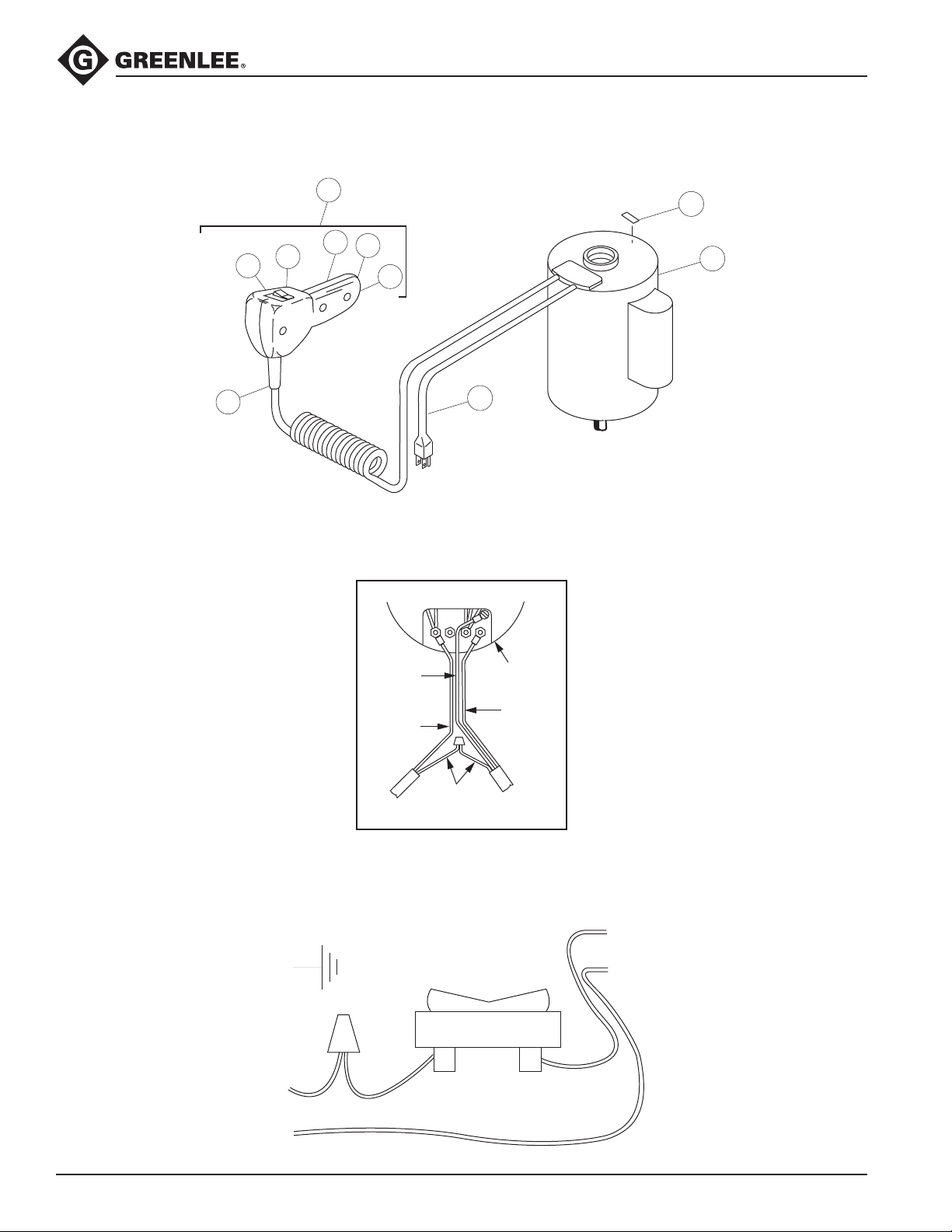
Motor Control Unit
8 50323636
16
87
86
85
90
89
4
88
20
Pendant Switch Control Wiring
GREEN
GROUND
L1
INCOMING LINE
L2
BLACK
WHITE
GREEN
WIRE LEAD
(GROUND)
WHITE
WIRE LEAD
(POWER)
BLACK
PENDANT
SWITCH CORD
WIRE LEAD
Pendant Switch Wiring
PENDANT
SWITCH
WIRING
BLACK
MOTOR
TOP VIEW
WHITE
WIRE LEAD
POWER
CORD
WHITE
L1
MOTOR CONNECTIONS
L2
WHITE
WHITE
Find Quality Products Online at: [email protected]
www.GlobalTestSupply.com
Page 17
Service (cont’d)
975 Hydraulic Power Pump
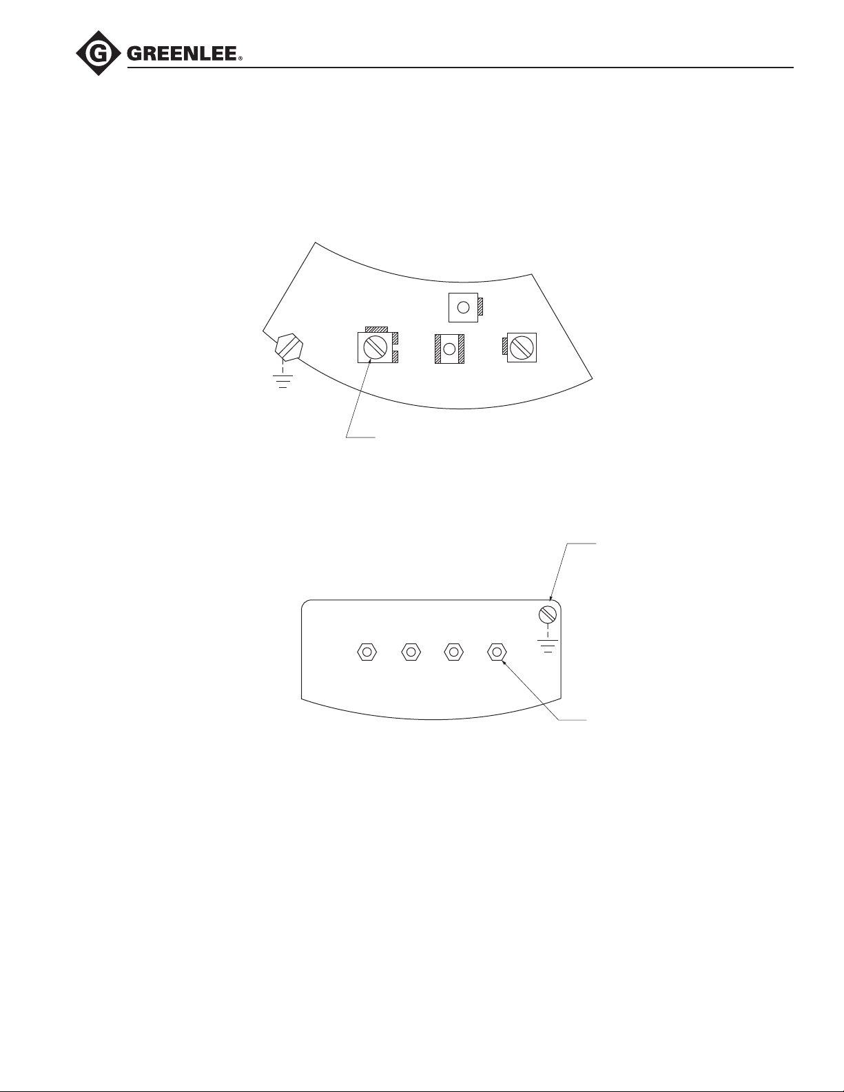
Motor Control Unit
115V Franklin Electric
3
L2
4 3 2 1
L1
WHITE
BLACK
YELLOW
4
ORANGE
BLUE
3X #10
115V General Electric
L1
RED
VIOLET
#6
L2
RED
ORANGE
4X #8
Find Quality Products Online at: [email protected]
www.GlobalTestSupply.com
Page 18
Service (cont’d)
975 Hydraulic Power Pump
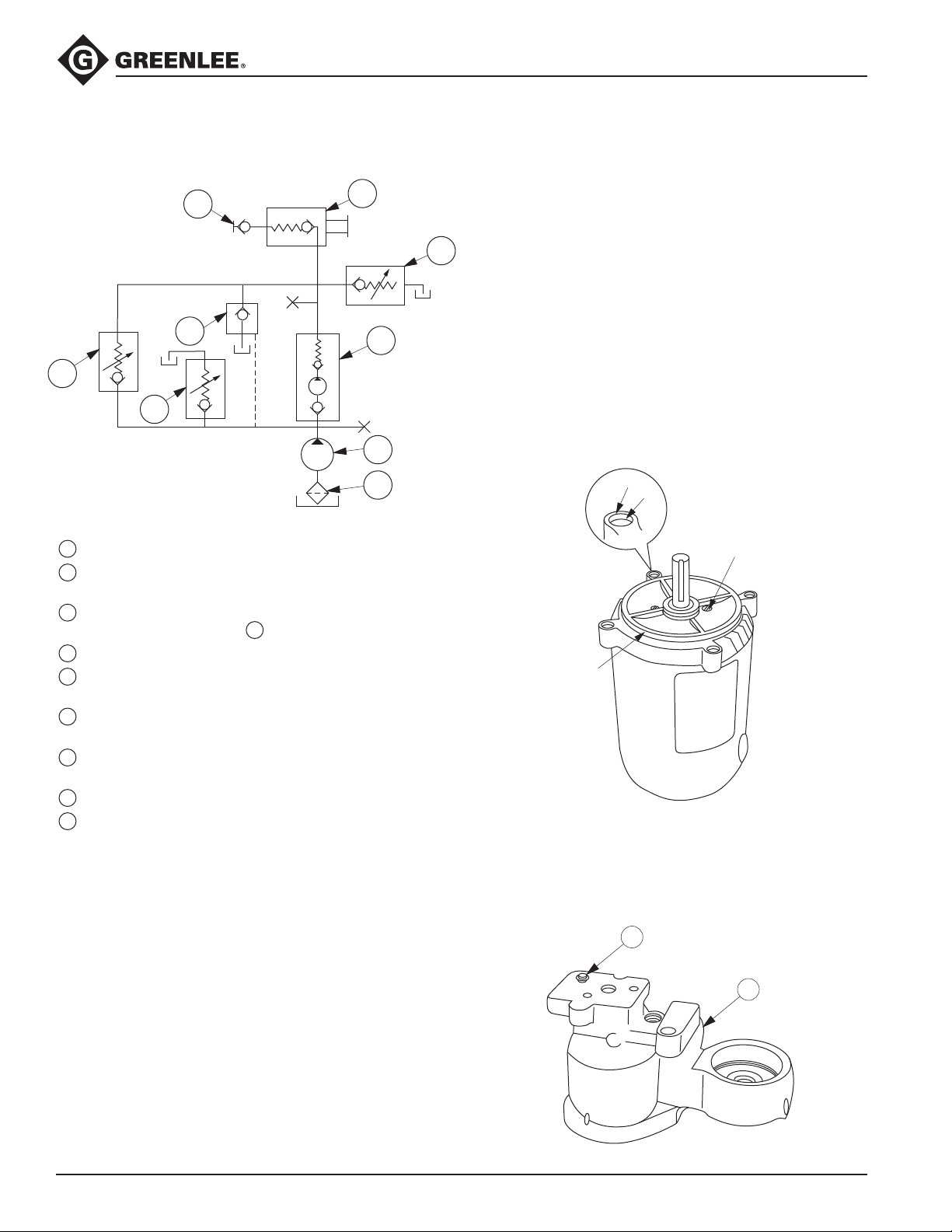
Hydraulic Schematic
9
7
8
5
4
3
2
1
1
Intake strainer, #50 mesh brass screen
2
Low-pressure pump
5.5 liters/min. (335 in
3
Low-pressure relief valve — 19 bar (275 psi) located
in pilot-operated valve
4
Low-pressure bypass check valve
5
High-pressure pump
.37 liters/min. (22.5 in
6
High-pressure relief valve
3
/min) at 3600 rpm (100%)
7
Piston
3
/min) at 3450 rpm (100%)
717/700 bar (10,400/10,000 psi)
7
Pilot-operated directional control valve
3 way, 2 position
8
Manually operated check valve
9
Female coupler half
Sealing Instructions for Assembly
Motor
If the motor has been disassembled, seal with a 3 mm
(1/8") bead of a silicone-based gasket/ange sealant,
such as Loctite
6
(A) To the mounting surface around the threads
®
587 Ultra Blue®, as follows:
(four locations)
(B) To the chamfer (four locations)
(C) Around the innermost machined circumference of
the mounting surface
Apply a 1.5 mm (1/16") bead of an RTV-type silicone-based sealant, such as Dow Corning 732™
Multipurpose Sealant, as follows:
Around the motor bearing screws (two locations)
(D)
Assemble immediately.
A
B
D
C
Driv-Lok Pin
Seal the Driv-Lok pin (73) to the pump block (84) with
a 1.5 mm (1/16") bead of an RTV-type silicone-based
sealant, such as Dow Corning 732™ Multipurpose
Sealant or equivalent.
73
84
Find Quality Products Online at: [email protected]
www.GlobalTestSupply.com
Page 19
Repairs
975 Hydraulic Power Pump
The following section and Figures describe pertinent
details for renishing ball seats and component
re-assembly and adjustments.
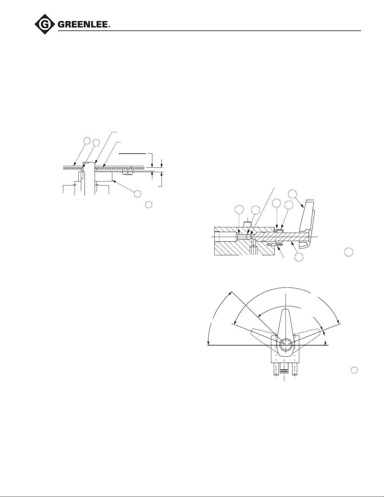
Motor Face Seal
When reassembling the motor, refer to Figure A1 for the
face seal seating dimension. Also, refer to this gure for
setting the vertical position of counterweight (32).
MOTOR SHAFT
22
21
MOTOR FACE
4.6mm (.180 inch)
4.1mm (.160 inch)
6mm (.234 inch)
32
Figure A1
8
Manual Release/Automatic Release Valve
Handle Setting
Refer to Figures A2 and A3. Thread in the shaft (62) until
it just touches the check ball (55) (in its spring-loaded
closed position). Slide collar (104) on the shaft. Position
the handle (61) at the location “Position 1,” (Figure A3),
with the other surface of the handle ush with the end of
the shaft. Lock in place. Rotate the handle to “Position
2,” (Figure A3). Slide the collar toward the valve body
until it contacts the 15.9 mm (5/8") diameter portion of
the control shaft. Rotate the lock collar clockwise until it
touches the stop pin, and lock in place.
When locking control handle and lock collar in
place, torque set screws tight to 2.8–3.4 Nm
(25–30inch-pounds).
7.938 mm (0.312") ø BALL SEAT
61
104
54
55
60
SET POSITION #1
45
CLOSED
STOP
62
STOP
PIN
BALL OPEN
112.5 (.99 mm [.039"])
Figure A2
135
POSITION 2
22.5 (REF.)
Figure A3
STOP
OPEN
8
8
Find Quality Products Online at: [email protected]
www.GlobalTestSupply.com
Page 20
Repairs (cont’d)
975 Hydraulic Power Pump
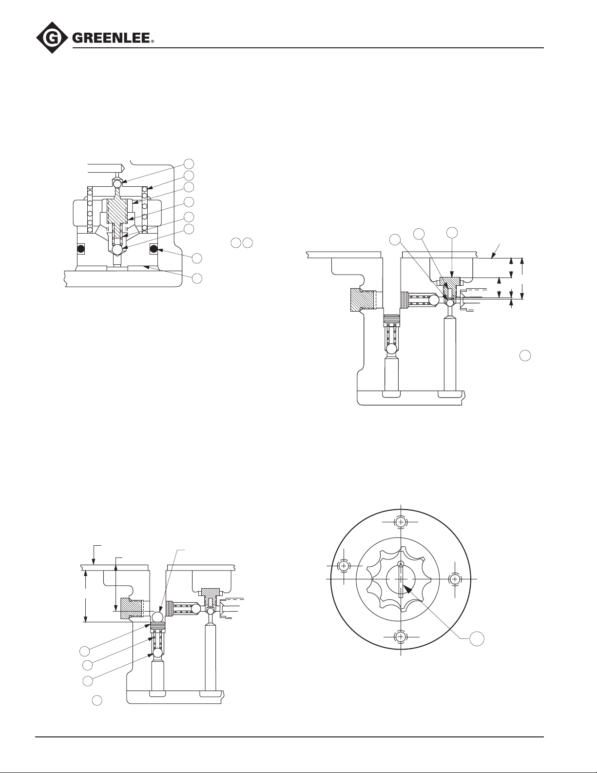
Low Pressure Relief Setting
Refer to Figure A4. Lightly bottom the stem (44) on the
ball (46). Then, back out the stem 3-1/2 turns. Tighten
nut (43). The resulting pressure setting should be
approximately 19.3 bar (280 psi).
42
47
43
44
45
46
3
Figure A4
49
48
7
Low-Pressure Bypass Check Pressure Adjustment
When properly set to the dimension shown in Figure A5,
the high pressure stage operation of the pump will be
delayed approximately one (1) second after the motor
starts. This delay is created by the closing time of the
pilot-operated valve.
This dimension must be increased if ball seat
Note:
depth is increased by more than .4 mm (1/64 inch).
Increasing the bypass pressure (CW rotation of adjusting screw—increase of set dimension) will shorten delay.
If delay becomes too short, the motor will not restart
when high pressure is held in the line. The motor should
restart with a maximum required off time of 1/2 to 1
second.
Decreasing the bypass pressure (CCW rotation of
adjusting screw) will increase delay. The pilot-operated
valve will not close if pressure is set too low.
Changes in oil temperature (viscosity) will affect the
amount of delay. The pumping delay will increase with
rising oil temperature (thinner oil).
High-Pressure Inlet Check Ball Travel
The amount of allowable ball travel is critical to the
optimum high pressure output (ow rate). Refer to
Figure A5-1. Carefully and accurately measure (depth
“mike”) the “A” dimension (top of pump block to seated
ball) and “B” dimension (top of pump block to head of
plug—at center). Carefully and accurately set the “C”
dimension (overall length of assembled plug and pin) of
a new plug and pin equal to “A” minus “B” minus .305 ±
.050 mm (.012 ± .002 inches).
105
42
79
TOP OF
PUMP BLOCK
B
A
C
TRAVEL
.305 mm +/– .050 mm
(.012 inch +/– .002 inch)
Figure A5-1
5
Low Pressure Pump Drive Pin
Assemble with cone point end in half-round keyway.
COVERPLATE
36.17 mm (1.424")
37.29 mm (1.468")
8 mm (5/16") Ø BALL
(used to make measurement)
Figure A6
78
69
70
71
Figure A5
Find Quality Products Online at: [email protected]
4
www.GlobalTestSupply.com
Page 21
Repairs (cont’d)
975 Hydraulic Power Pump
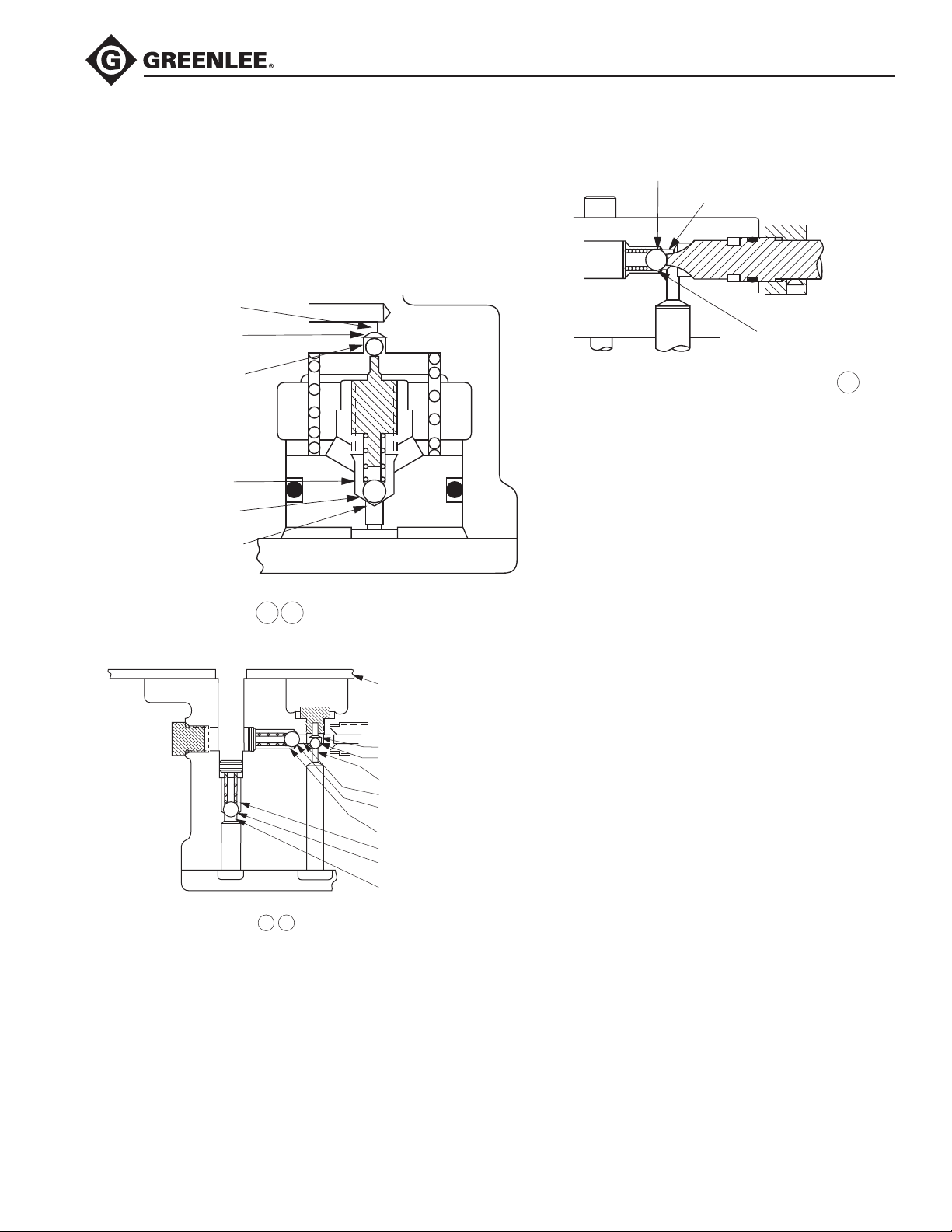
Ball Seat Refinishing
Refer to Figures B2, B3, and B4 for the proper drill size
to renish the conical seat and nish ream size.
These operations must be performed with the pump
or valve block properly held and using a drill press.
Only a very small amount of material should be removed.
3.175 mm (.125") Ø REAM
4.76 mm (.187") Ø BALL SEAT
(P.O. VALVE)
7.14 mm (.281") Ø DRILL
11.51 mm (.453") Ø DRILL
6.35 mm (.250") Ø BALL SEAT
(LO-P RELIEF VALVE)
4.76 mm (.187") Ø REAM
7.94 mm (0.312") Ø BALL SEAT
(LINE CHECK VALVE)
7.14 mm (0.281") Ø REAM
9.53 mm (0.375") Ø DRILL
Figure B4
8
Figure B2
Figure B3
3
7
COVERPLATE
8.43 mm (“Q” 0.332") Ø DRILL
4.76 mm (0.187") Ø BALL SEAT
(INTAKE CHECK)
3.45 mm (#29 0.136") Ø REAM
4.76 mm (0.187") Ø REAM
7.14 mm (0.281") Ø BALL SEAT
(DISCHARGE CHECK)
9.35 mm (“U” 0.368") Ø DRILL
9.35 mm (“U” 0.368") Ø DRILL
7.14 mm (0.281") Ø BALL SEAT
(BYPASS CHECK)
4.76 mm (0.187") Ø REAM
4
5
Find Quality Products Online at: [email protected]
www.GlobalTestSupply.com
Page 22
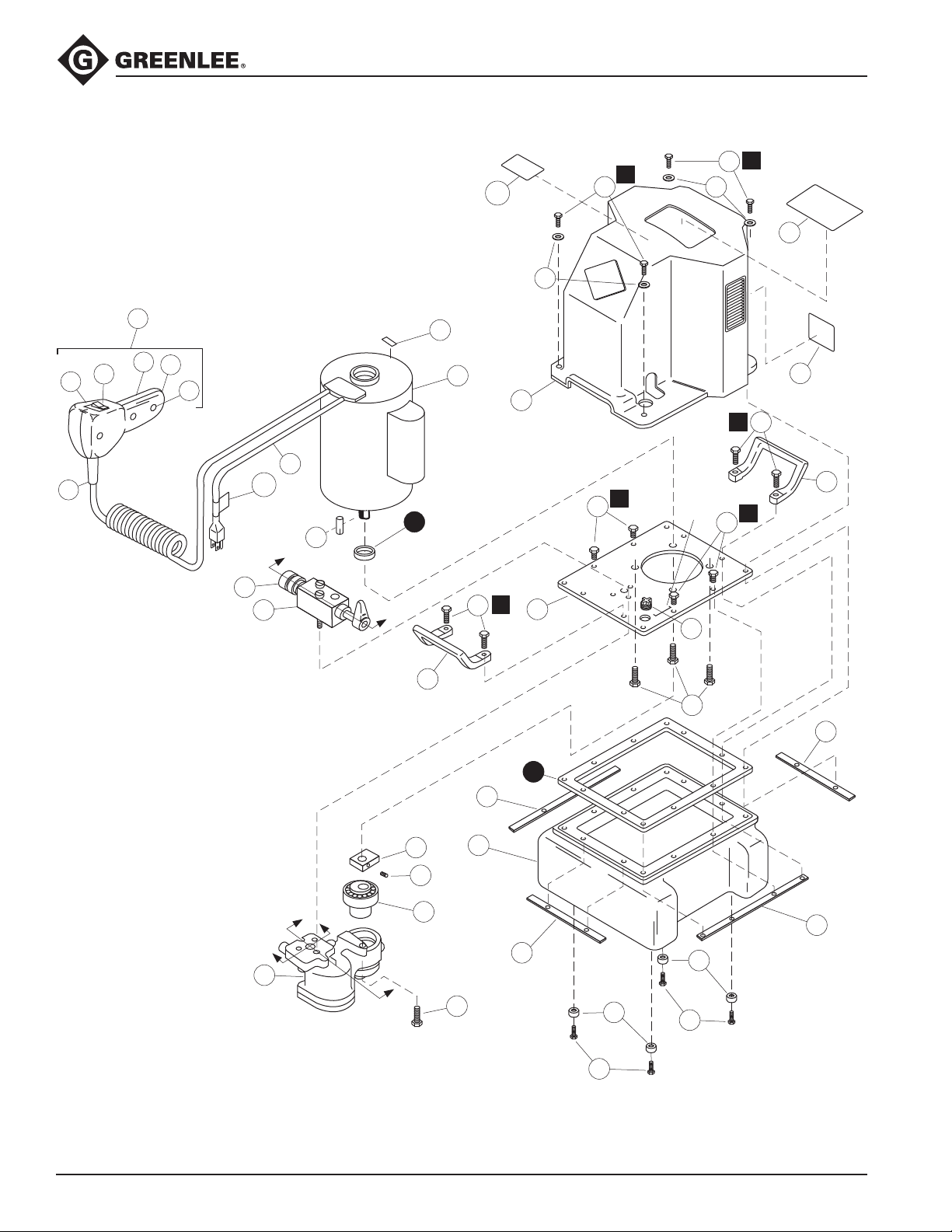
Exploded View
110
975 Hydraulic Power Pump
1
1
7 28
28
7
3
8
87
86
85
90
89
88
20
111
34
Fig. A4
9
14
16
4
10
1
1
21
1
2
1
22
7
Serial
No.
6
19
1
7
15
2
1
12
23
13
32
33
17
Figs A1 & A3
18
Find Quality Products Online at: [email protected]
www.GlobalTestSupply.com
Fig A2
11
13
12
35
24
25
24
25
Page 23
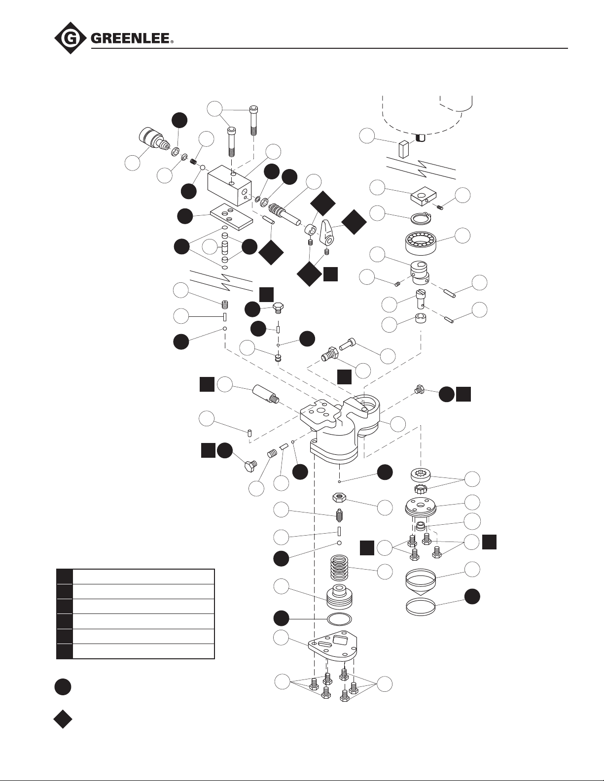
Exploded View—Pump Block
65
52
54
9
53
55
59
58
56
69
70
71
6
72
See Driv-Lok Pin under
Sealing Instructions
for Assembly in the
Service Section.
73
5
68
74
57
79
105
66
64
108
4
63
42
60
62
104
975 Hydraulic Power Pump
34
32
36
61
38
2
40
77
103
76
75
3
84
79
33
41
39
78
4
Torque Table
1 1.13–1.35 Nm 10–12 in-lb
2 2.8–3.4 Nm 25–30 in-lb
3 110 Nm 80 ft-lb
4 27 Nm 20 ft-lb
5 34 Nm 25 ft-lb
6 68 Nm 50 ft-lb
50343696
Hydraulic Repair Kit
50354647
Release Knob Retrot Kit
69
70
44
45
46
48
49
50
71
7
42
43
2
7
47
7
80
81
102
7
82
83
2
Find Quality Products Online at: [email protected]
www.GlobalTestSupply.com
Page 24
975 Hydraulic Power Pump
Parts List
Key Part No. Description Qty
1 50335189 Carrying Handle ........................................................................................ 2
2 90537092 1/4–20 x 1-1/4" Hex Head Screw ............................................................. 4
3 50337211 Decal ......................................................................................................... 1
4 91863392 Motor, 115 VAC, 1/2 hp ............................................................................. 1
GE 5CK36JN268X
Franklin 1103007415
SERVICE PARTS: GE FE
1
Capacitor
Cover, Cap
6 52058082 Plug with O-ring ........................................................................................ 1
7 90505204 1/4–20 x 3/4" Hex Head Screw ............................................................... 18
8 50323636 Pendant Switch Unit (includes 85-90) ....................................................... 1
9 90508076 Coupling ................................................................................................... 1
10 50334891 Shroud....................................................................................................... 1
11 50334905 Reservoir .................................................................................................. 1
12 50335359 Short Retaining Strap ............................................................................... 2
13 50335367 Long Retaining Strap ................................................................................ 2
14 50335375 Release Valve Unit .................................................................................... 1
(includes 52-66, 104, 108)
15 50337238 ID Decal ..................................................................................................... 1
16 50158325 Arrow Decal .............................................................................................. 1
17 Eccentric Unit ............................................................................................ 1
(see next page for breakdown)
18 Pump Block Unit ....................................................................................... 1
(see next page for breakdown)
19 90505301 Hex Hd. Cap Screw 3/8–16 x 1.00" ......................................................... 3
20 91862965 Power Cord ............................................................................................... 1
*21 90536827 Seal .......................................................................................................... 1
22 50335170 Cover Plate ............................................................................................... 1
*23 50326279 Cover Plate Gasket .................................................................................. 1
24 90538293 Rubber Foot ............................................................................................. 4
25 90511859 Screw, 1/4–20 x 1/4" ................................................................................ 4
28 90523393 1/4" Flat Washer ...................................................................................... 4
32 50335278 Counterweight ........................................................................................... 1
33 90512693 Set Screw, 1/4–20 x 1/4" .......................................................................... 1
34 50145576 Motor Shaft Key, 3/16" x 1-3/8" ................................................................ 1
35 90505336 Hex Hd. Cap Screw, 3/8–16 x 1.50" ......................................................... 1
36 90537076 Retaining Ring .......................................................................................... 1
Greenlee No. 91863775
Manufacturer No. 111A271P1
Greenlee No. 91865026 91865042
Manufacturer No. 111B275AA1 276756101
91865034
1
275469110
2
2
Find Quality Products Online at: [email protected]
www.GlobalTestSupply.com
Page 25

975 Hydraulic Power Pump
Parts List (cont’d)
Key Part No. Description Qty
38 50335260 Eccentric Shaft .......................................................................................... 1
39 90506995 Rollpin, 3/16" x 1" .................................................................................... 1
40 90507916 Set Screw, 10–32 x 1/4" ............................................................................ 1
41 90537041 Ball Bearing, #3206 ................................................................................... 1
*42 90506782 Ball, 3/16" ................................................................................................ 2
43 90500164 Jam Nut, 1/2–20 ....................................................................................... 1
44 50335200 Stem .......................................................................................................... 1
45 50325345 Spring, .240" O.D x .750" ........................................................................ 1
*46 90506790 Ball, 1/4" .................................................................................................. 1
47 90537017 Spring, 1.460" O.D x 1.500" .................................................................... 1
48 50335197 Auto Valve Piston ..................................................................................... 1
*49 90503406 O-ring, 1-5/8" x 2" x 3/16" ....................................................................... 1
50 50335219 Pump Block Cover .................................................................................... 1
*52 90535030 Retaining Ring .......................................................................................... 1
53 90534689 Plain Flat Type “A" Washer #10 ................................................................ 1
54 90535103 Compression Spring, .240" O.D. x .687" .................................................. 1
*55 90506804 Ball, 5/16" ................................................................................................. 1
56 50326228 Coupling .................................................................................................... 1
*57 90512901 Back-up Ring, 3/8" x 1/2" x 1/16" ........................................................... 2
*58 90501683 O-ring, 3/8" x 1/2" x 1/16" ....................................................................... 2
*59 50326260 Gasket ...................................................................................................... 1
+60 90512693 Set Screw, 1/4–20 x .38" .......................................................................... 2
+61 50347969 Release Valve Knob ................................................................................ 1
62 50335413 Control Shaft ............................................................................................. 1
*63 90538277 Back-up Ring, 1/2" x 5/8" ........................................................................ 1
*64 90509129 O-ring, 1/2" x 5/8" x 1/16" ....................................................................... 1
65 90534964 Cap Screw, 5/16–18 x 2.50" ................................................................... 2
66 50326236 Release Valve Body ................................................................................. 1
*68 90536983 O-ring Plug (includes 107) ......................................................................... 1
69 90537122 Jam Screw, 7/16" ...................................................................................... 2
70 90537025 Spring, .240" O.D x .810 .......................................................................... 2
*71 90504364 Ball, 9/32" ................................................................................................ 2
72 50060678 High Pressure Relief Valve ........................................................................ 1
73 90537068 Type “D” Driv-Lok Pin, 1/4" x 1/2" ........................................................... 1
74 50343106 Insert, Cavity ............................................................................................ 1
75 50335316 High Pressure Bushing ............................................................................. 1
76 50335324 High Pressure Piston ................................................................................ 1
77 50335251 Drive Shaft ............................................................................................... 1
78 50329340 Drive Pin, 1/8" x 5/8" ................................................................................ 1
*79 90536991 O-ring Plug (includes 106) ......................................................................... 1
80 90535170 Gerotor ..................................................................................................... 1
Find Quality Products Online at: [email protected]
www.GlobalTestSupply.com
Page 26
975 Hydraulic Power Pump
Parts List (cont’d)
Key Part No. Description Qty
81 50341979 Lower Gerotor Plate Unit (includes 102) .................................................. 1
82 50335243 Filter .......................................................................................................... 1
*83 90537661 O-ring, 2-3/8" x 2-5/8" x 1/8" ................................................................... 1
84 50335332 Pump Block............................................................................................... 1
85 50323709 Faceplate Decal ....................................................................................... 1
86 91862655 Switch, Rocker ......................................................................................... 1
87 50319027 Handle, Right Half .................................................................................... 1
88 90534417 Self-Tapping Screw, 6–20 x 5/8" .............................................................. 3
89 50319019 Handle, Left Half ...................................................................................... 1
90 50323628 Cord, Pendant ........................................................................................... 1
102 90538390 Bearing, Bronze ....................................................................................... 1
103 90533208 Bearing, Bronze 1/2" x 5/8" x 1/2" ............................................................ 1
+104 50348868 Shaft Stop Collar ....................................................................................... 1
*105 90538161 Pin, 1/8" x 1/4" Driv-Lok ........................................................................... 1
+108 90500784 Roll Pin, .187" Dia. x 3/4" Long ................................................................ 1
109 4016GB Hydraulic Oil, 1 gal, ea. .......................................................................... 1.5
4017GB Hydraulic Oil, 1 qt, ea. ............................................................................... 6
110 500 2581.3 Decal, caution ........................................................................................... 1
111 502 2510.3 Decal, caution ........................................................................................... 1
Greenlee Hydraulic Oil (Mobil DTE® 13M)
90510593 / 4016GB 1 gallon
90508068 / 4017GB 1 quart
* Parts included in Hydraulic Repair Kit No. 50343696
+ Parts included in Release Knob Retrot Kit 50354647
1
440 μfd. Grainger #1A569 1B/16Ø x 3-3/8
2
460-552 μfd. Grainger #4X070 1B/16Ø x 4-3/8 Aero PSA5R 10460N
PSA4R 10400N
i
Find Quality Products Online at: [email protected]
www.GlobalTestSupply.com
 Loading...