

Page 1
INSTRUCTION MANUAL
Deluxe Force Gauge
999 2021.2 © 2002 Greenlee Textron IM 1255 REV 3 1/02
00967
Read and understand all of the instructions and
safety information in this manual before operating
or servicing this tool.
Page 2

00967 Deluxe Force Gauge
Table of Contents
Description .....................................................................2
Purpose..........................................................................2
Important Safety Information..........................................3
Principle of Operation.....................................................4
Identification ................................................................... 4
Specifications ................................................................. 4
Operating Instructions
Setup / Installation ..................................................5-6
Operation ................................................................... 7
Configuration .............................................................8
Maintenance
Exploded View / Parts List - Roller Assembly............9
Digital Display .....................................................10-11
Wiring Connections for Strain Gage Monitor ........... 12
Description
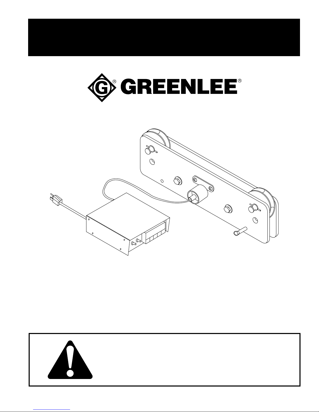
The Greenlee 00967 Deluxe Force Gauge is a cable
puller accessory intended to monitor the force developed
when cable is pulled into conduit. The 00967 includes
provisions for mounting of the Ultra Tugger™ Cable
Puller and the Ultra Tugger™ boom. If you want to use
the 00967 Deluxe Force Gauge with other cable pullers,
it must be installed to withstand the resistance of the
rope rolling across the five rollers.
Safety
Safety is essential in the use and maintenance of
Greenlee tools and equipment. This manual and any
markings on the tool provide information for avoiding
hazards and unsafe practices related to the use of this
tool. Observe all of the safety information provided.
Purpose of this Manual
This manual is intended to familiarize all personnel with
the safe operation and maintenance procedures for the
following Greenlee tool:
00967 Deluxe Force Gauge
Keep this manual available to all personnel.
Replacement manuals are available upon request at no
charge.
Greenlee Textron / Subsidiary of Textron Inc. 2 4455 Boeing Dr. • Rockford, IL 61109-2988 USA • 815/397-7070
All specifications are nominal and may change as design improvements occur. Greenlee Textron shall not be liable for damages
resulting from misapplication or misuse of its products.
KEEP THIS MANUAL
Page 3
00967 Deluxe Force Gauge
IMPORTANT SAFETY INFORMATION
SAFETY
ALERT
SYMBOL
This symbol is used to call your attention to hazards
or unsafe practices which could result in an injury or
property damage. The signal word, defined below,
indicates the severity of the hazard. The message
after the signal word provides information for
preventing or avoiding the hazard.
Immediate hazards which, if not avoided, WILL
result in severe injury or death.
Hazards which, if not avoided, COULD result in
severe injury or death.
Hazards or unsafe practices which, if not avoided,
MAY result in injury or property damage.
Electric shock hazard.
• Do not expose tool to rain or use
in wet or damp locations.
• Disconnect from power source
before servicing or dismantling
the gauge.
• Unplug the tool when not in use.
Failure to observe this warning can
result in severe injury or death.
Make sure the switch is in the OFF position before
connecting this tool to a power source. Accidental
start-up can result in serious injury.
Keep hands away from rope and
rollers. Rope can crush a hand.
Failure to observe this warning can
result in severe injury or death.
Read and understand all of the
instructions and safety information
in this manual before operating or
servicing this tool.
Failure to observe this warning can
result in severe injury or death.
Do not pull anything other than the pulling rope
through the force gauge. Metallic objects such as
pulling grips, clevises and wire rope will damage
the rollers.
Failure to observe this precaution can result in
damage to the force gauge.
Service should be performed by
Read and understand the instruction manual
supplied with your puller. Failure to follow instructions and safety information can result in severe
injury or death.
Greenlee Textron / Subsidiary of Textron Inc. 3 4455 Boeing Dr. • Rockford, IL 61109-2988 USA • 815/397-7070
an authorized Greenlee service
center only.
Page 4

Principle of Operation
g
t
00967 Deluxe Force Gauge
The 00967 Deluxe Force Gauge calculates pulling force
by measuring the tension of the rope. The accuracy of
this method is ± 5% of the pulling force.
The two outer rollers guide the rope into and out of the
force gauge, and provide 14 degrees of deflection. This
deflection in the rope path transfers 1/4 of the pulling
tension to the center roller.
Main Components Identification
The tension on the rope is measured at the center roller.
That roller presses against a load cell that sends an
electronic signal to the digital display unit. The display
unit multiplies the signal by 4 and shows the pulling
tension in pounds or kilograms.
To provide the highest accuracy, the force gauge has
been calibrated with the rollers in motion. When the pull
is stopped or the rope is relaxed, the displayed value
may be somewhat lower than the actual tension.
Hitch Pin with Clip
Puller/Gau
e Moun
Force Gauge
Roller Assembly
Patch Cord
Digital Display Unit
Specifications
Capacity ............................................4536 kg (10,000 lb)
Power Input ............................................ 120 VAC, 60 Hz
Power Output ...................................................... 10 VDC
Weight ....................................................... 13.6 kg (30 lb)
Maximum Rope Size ................................... 22 mm (7/8")
Boom/Gauge Mount
Greenlee Textron / Subsidiary of Textron Inc. 4 4455 Boeing Dr. • Rockford, IL 61109-2988 USA • 815/397-7070
Page 5
Setup / Installation
00967 Deluxe Force Gauge
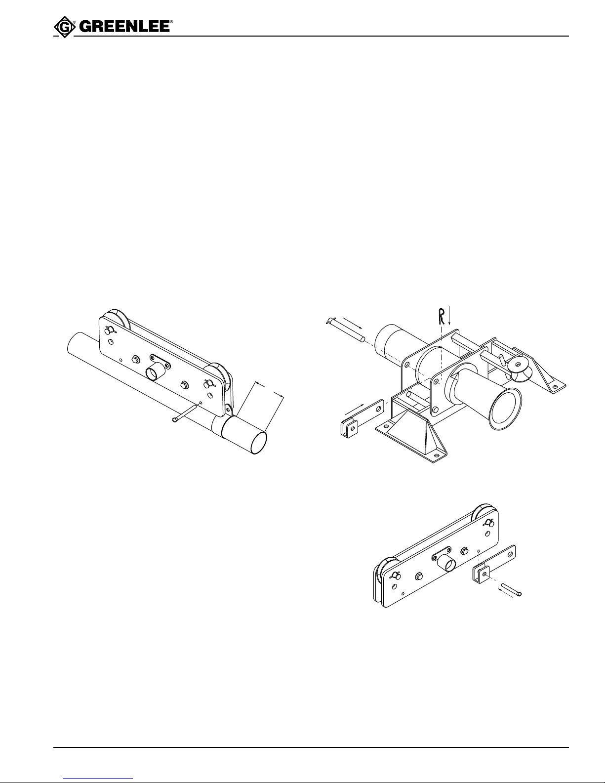
Install the force gauge roller assembly using one of the
two mounting adapters provided.
Mounting to Boom Assembly
1. See the manual supplied with the Ultra Tugger™.
After attaching a boom tube to the boom mount, see
Steps 2 - 5 to attach the boom/gauge mount. Then
finish setting up the cable puller.
2. See the illustration. Slide the boom/gauge mount
onto the boom tube. Position it about 4" from the
boom mount as shown.
3. Tighten the set screw.
4. Place the force gauge roller assembly onto the
gauge mount so that the tabs of the mount go
between the roller side plates, as shown.
5. Align the holes and insert the hitch pin.
Mounting to the Ultra Tugger™
1. See the manual supplied with the Ultra Tugger™.
Set up the cable puller with the chain mount, pipe
sheave adapter, or floor mount.
2. See the illustration. Position the puller/gauge mount
between the side plates of the puller. Align the holes
as shown.
3. Insert the hitch pin through the holes.
4. Secure the hitch pin with a hitch pin clip.
5. Place the roller assembly onto the puller/gauge
mount so that one side plate of roller assembly fits
into the U-shaped slot of the mount. Align the holes
as shown.
6. Insert the hitch pin through the holes.
4.00
Greenlee Textron / Subsidiary of Textron Inc. 5 4455 Boeing Dr. • Rockford, IL 61109-2988 USA • 815/397-7070
Page 6
Setup
Setup / Installation
00967 Deluxe Force Gauge
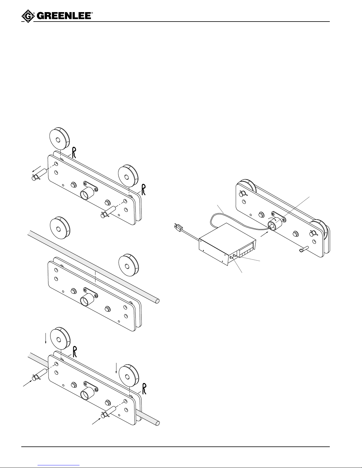
Installing the Rope
1. Remove the hitch pin clips.
2. Remove the hitch pins.
3. Remove the outer rollers.
4. Lay the rope over the three inner rollers.
5. Replace the outer rollers.
6. Replace the hitch pins.
7. Replace the hitch pin clips.
Electrical Connection
1. Plug the patch cable into the load pin.
2. Twist the front of the connector clockwise to lock it
in place.
3. Plug the other end of the patch cable into the back
of the digital display unit. Turn the locking nut
clockwise to lock.
4. Plug the digital display into a 115 VAC receptacle.
5. Use the MAIN POWER toggle switch to turn the
display unit ON. The display will show “RST” followed by “STRN” followed by the force reading.
Allow the unit to warm up for 5 minutes.
Note: If the optional strip recorder is used, you may plug
it into the receptacle at the back of the digital display
unit. Use the REAR POWER toggle switch to apply
power to that receptacle.
Load Pin
Patch Cable
Main Power
Switch
Rear Power
Switch
Greenlee Textron / Subsidiary of Textron Inc. 6 4455 Boeing Dr. • Rockford, IL 61109-2988 USA • 815/397-7070
Page 7
Operation
00967 Deluxe Force Gauge
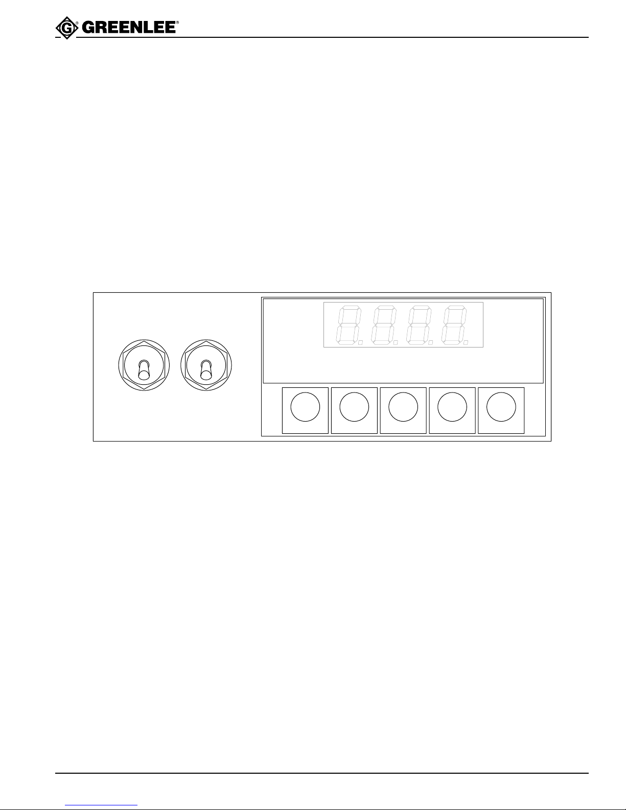
The front panel has five keys:
SETPTS (setpoints): not used
NT/GRS (net/gross): Press to recall the peak force
reading.
TARE: Press to zero the display.
MENU: Press to enter the configuration/calibration mode.
RESET: Press to reset the peak or tare readings.
M
A
N
P
O
W
E
R
ON
I
OFF
ON
OFF
R
E
A
R
P
O
W
E
R
SETPTS NT/GRS TARE MENU RESET
With no load on the rope, the display should read “0”
(± 4.5 kg or 10 lbs). Slight variations as the unit sits idle
are normal.
If the display is off by more than 4.5 kg or 10 lbs, press
TARE to reset the zero point.
Press the NT/GRS key at any point during or after the
pull to view the peak reading. The peak reading will flash
on the display. Press NT/GRS again to return to the
present force reading.
To reset the peak reading, press RESET while the peak
reading is flashing on the display.
Note: See the Strain Gage Meter manual for more
information.
Greenlee Textron / Subsidiary of Textron Inc. 7 4455 Boeing Dr. • Rockford, IL 61109-2988 USA • 815/397-7070
Page 8
00967 Deluxe Force Gauge
Configuration
Under normal circumstances it is not necessary to enter the configuration mode. Directions for this can be found in the
Strain Gage Meter operator’s manual supplied.
To display kilograms instead of pounds change the value for: “RD.S.O., RD2” to 2268
“OT.S.O., RD2” to 3629
In the event any of the default values set by the factory are changed by accident, the Greenlee default values are
listed below.
Menu Topic Setting/Value
INPT (signal input) 100m
DEC.P (decimal point) FFFF.
RD.S.O. (reading scale and offset)
IN1 (no load signal input) ______
RD1 (no load display reading) 0000
IN2 (5000 pound signal input) ______
RD2 (5000 pound display reading) 5000
(2268 for kilograms)
RD.CF (reading, configuration)
R.1 (ratiometric operation) R
R.2 (input resolution) 4
R.3 (filtering) F
R.4 (gross/net peak display) P
S1.CF (setpoint 1 configuration) not active
S2.CF (setpoint 2 configuration) not active
S1DB (setpoint 1 deadband) not active
S1DB (setpoint 2 deadband) not active
OT.CF (output enabled/disabled)
0.1 (output enabled/disabled) E
0.2 (voltage/current output) V
0.3 (net/gross reading) N
OT.S.O. (output scale and offset
RD1 (no load output reading) 0000
OUT.1 (no load output signal) 00.00
RD2 (loaded output reading) 8000
(3629 for kilograms)
OUT.2 (loaded output signal) 08.00
LK.CF (lockout configuration)
SP. (setpoint lockout) E
RS. (reset lockout) E
S1 Dip Switch Positions
1 - Closed
2 - Open
3 - Closed
4 - Open
5 - Open
6 - Closed
7 - Open
8 - Open
Greenlee Textron / Subsidiary of Textron Inc. 8 4455 Boeing Dr. • Rockford, IL 61109-2988 USA • 815/397-7070
Page 9
00967 Deluxe Force Gauge
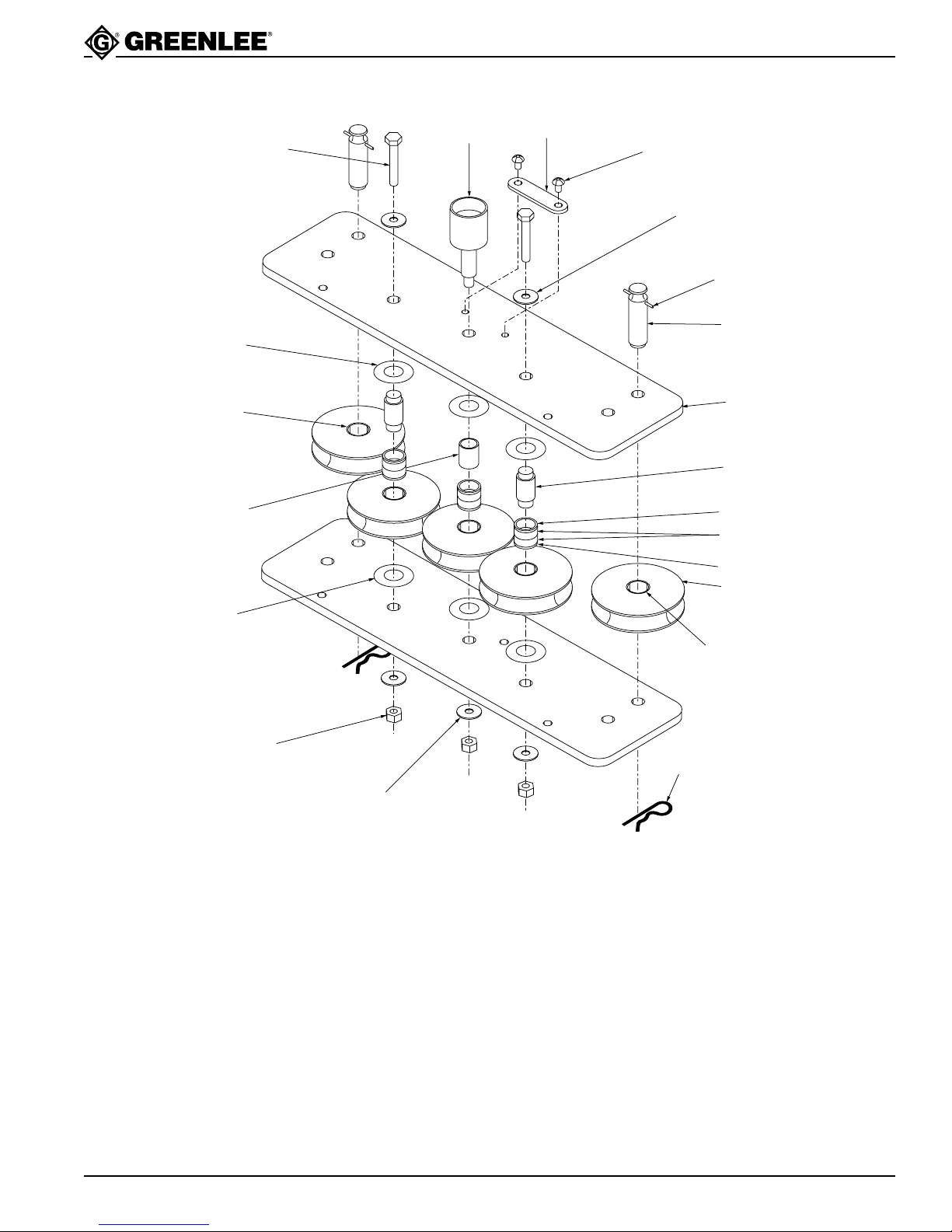
Exploded View / Parts List—500 0922.2 Roller Assembly
15
3
7
13
12
5
11
14
10
4
6
2
16
17
16
1
7
8
14
Key Part No. Description Qty
1 500 0727.0 Roller................................................................ 5
2 500 0729.7 Shaft................................................................. 2
3 500 0730.0 Load pin............................................................1
4 500 0732.7 Pin, removable ................................................. 2
5 500 0733.5 Rotational stop ................................................. 1
6 500 0737.8 Side plate ......................................................... 2
7 501 7916.0 Washer, flat, 1.00 x 1.50 x .031 fiber................6
8 905 0011.3 Nut, hex, 1/2-20 regular....................................3
9 905 0302.3 Clip, hitch pin #8............................................... 2
10 905 0700.2 Rollpin, .187 x 1.50...........................................2
11 905 3522.7 Screw, cap, 3/8-16 x .625 button head............. 2
12 905 4875.2 Inner race, Torrington #1620............................ 1
13 905 4841.8 Bearing, NL #1620-9 ........................................ 2
13
9
Key Part No. Description Qty
14 905 4845.0 Washer, flat, .500 x 1.50 x .062...................... 10
15 905 4846.9 Screw, cap, 1/2-20 x 2.75 hex head................. 2
16 905 4876.0 Seal, CR #9815................................................ 6
17 905 4840.0 Bearing, Torrington #JTT1618 ......................... 6
Attachments
Key Part No. Description Qty
N/S 500 0966.4 Patch cord ........................................................ 1
N/S 500 0736.0 Puller/gauge mount .......................................... 1
N/S 500 0739.4 Boom/gauge mount.......................................... 1
N/S 905 0530.1 Set screw (for boom/gauge mount).................. 1
N/S 905 4844.2 Hitch pin ........................................................... 1
Greenlee Textron / Subsidiary of Textron Inc. 9 4455 Boeing Dr. • Rockford, IL 61109-2988 USA • 815/397-7070
Page 10
Digital Display
00967 Deluxe Force Gauge
2
21
16
20
1
10
9
18
12
13
Greenlee Textron / Subsidiary of Textron Inc. 10 4455 Boeing Dr. • Rockford, IL 61109-2988 USA • 815/397-7070
Page 11
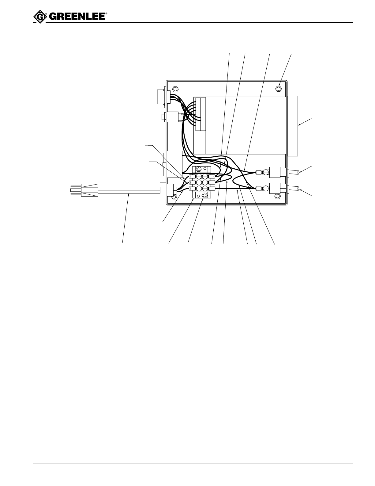
00967 Deluxe Force Gauge
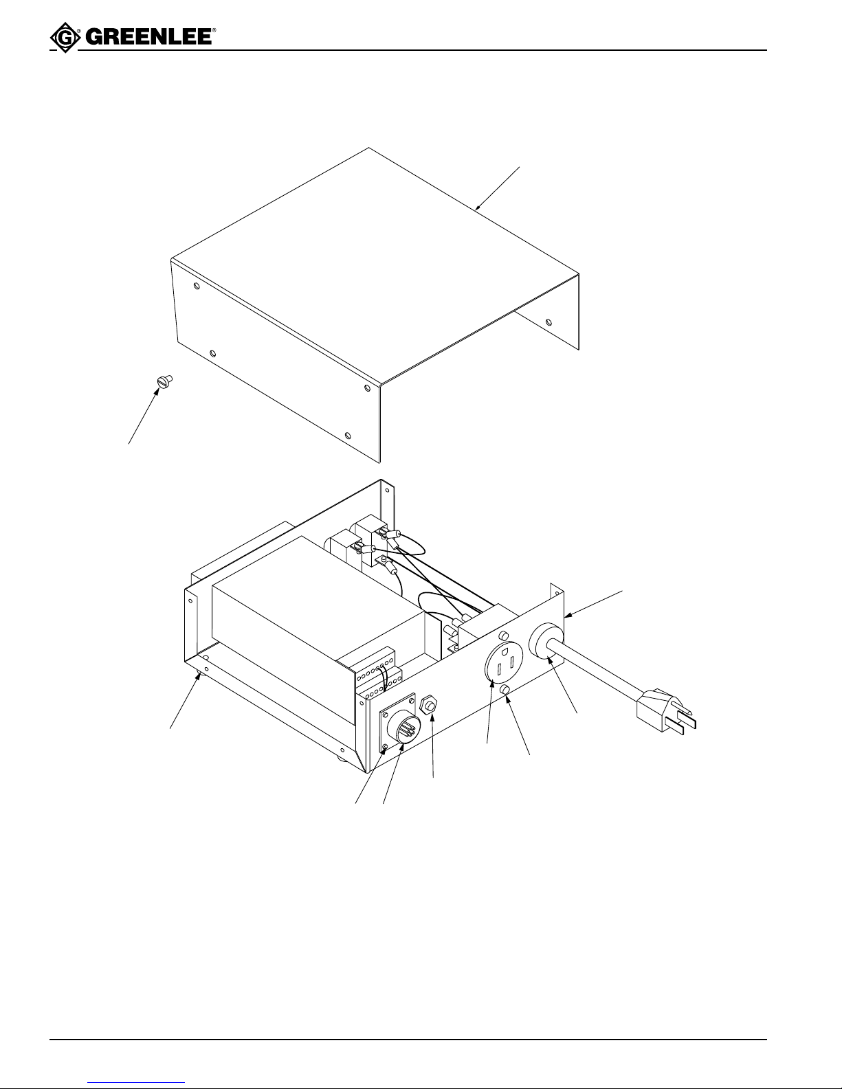
Parts List—Digital Display
GREEN
WHITE
BLACK
5227
17
15
11
11
8
14 17,19 66 33 4
500 0965.6 Digital Display Assembly
Key Part No. Description Qty
1 500 0953.2 Box ........................................................................1
2 500 0954.0 Cover ..................................................................... 1
3 500 0955.0 Wire unit, black switch...........................................2
4 500 0956.7 Wire unit, black monitor ........................................1
5 500 0957.5 Wire unit, black receptacle.....................................1
6 500 0958.3 Wire unit, white neutral..........................................2
7 500 0959.1 Wire unit, green ground.........................................1
8 500 0960.5 Power cord ............................................................1
9 918 6325.2 Receptacle, 115 Vac ..............................................1
10 918 6326.0 Strain relief ............................................................1
11 918 6319.8 Switch (with mounting nuts) .................................2
Key Part No. Description Qty
12 500 0961.3 Phone jack unit ......................................................1
13 500 0962.1 Receptacle unit, 6-pin ............................................1
14 918 6317.1 Terminal block .......................................................1
15 918 6822.0 Strain gage monitor ...............................................1
16 905 3934.6 Bumper .................................................................. 4
17 905 0633.2 Nut, hex, #8-32 ......................................................6
18 905 0763.0 Screw, cap, #8-32 x .250 socket head ...................2
19 905 1532.3 Screw, machine, #8-32 x.500 round head .............2
20 905 4874.4 Screw, cap, #4-40 x .250 socket head ...................4
21 905 3194.9 Screw, self-tapping, #10-16 x .250 Phillips head...8
22 500 5371.0 Wire unit, receptacle ground..................................1
Greenlee Textron / Subsidiary of Textron Inc. 11 4455 Boeing Dr. • Rockford, IL 61109-2988 USA • 815/397-7070
Page 12

Wiring Connections for Strain Gage Monitor
6-Pin Receptacle Wire Color Monitor Connection
Pin 1 Red TB2 2
Pin 2 Green TB2 6
Pin 3 White TB2 7
Pin 4 Black TB2 1
Pin 5 - Pin 6 - -
Phone Jack Unit Wire Color Monitor Connection
Positive Red TB1 10
Ground Black TB1 12
Power Connections Wire Color Monitor
Monitor Wire Unit Black TB1 7
Neutral Wire Unit White TB1 8
Ground Wire Unit Green TB1 9
Greenlee Textron / Subsidiary of Textron Inc.
4455 Boeing Drive, Rockford, IL 61109-2988 USA
Customer Service (International): 815/397-7070 • Fax: 815/397-9247
Customer Service (North America): 800/435-0786 • USA Fax: 800/451-2632, 815/397-1865
Canada Fax: 800/524-2853
www.greenlee.textron.com
Printed in the USA
 Loading...