

Page 1
INSTRUCTION MANUAL
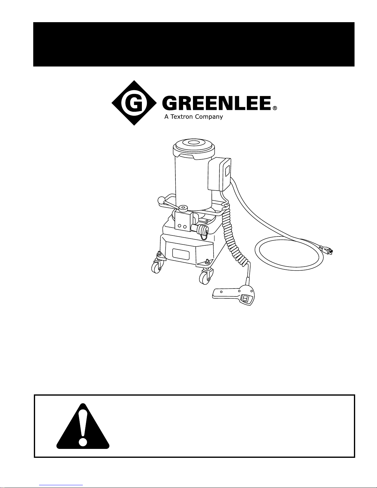
960 PS Series
Hydraulic Power Pumps
Beginning with Serial Number KS17000
999 8707.4 © 2002 Greenlee Textron IM 1007 REV 15 12/02
Read and understand all of the instructions and
safety information in this manual before operating
or servicing this tool.
Page 2
960 PS Series Hydraulic Power Pumps
Table of Contents
Description, Safety, and Purpose ..................................2
Important Safety Information ..................................... 3–4
Specifications.................................................................5
Setup..............................................................................6
Motor Wiring Diagram.................................................... 7
Operation ....................................................................... 8
Maintenance and Service .............................................. 9
Troubleshooting ...........................................................10
Illustrations.............................................................11–12
Parts List ................................................................13–14
Motor Parts List............................................................15
SA Control Valve .........................................................16
Description
The Greenlee 960 PS Series Hydraulic Pumps are
electrically powered, two-stage pumps that develop a
maximum of 689.5 bar (10,000 psi). The pumps are
intended to provide hydraulic power for an accessory
with a single-acting ram (hydraulic cylinder) such as a
Greenlee conduit bender or cable cutter.
Fill unit with hydraulic oil before
operating pump.
Failure to fill unit with oil will result in
damage to the pump.
Safety
Safety is essential in the use and maintenance of
Greenlee tools and equipment. This manual and any
markings on the tool provide information for avoiding
hazards and unsafe practices related to the use of this
tool. Observe all of the safety information provided.
Purpose of this Manual
This manual is intended to familiarize all personnel with
the safe operation and maintenance procedures for the
following Greenlee tools:
960 PS Series Hydraulic Pumps
Keep this manual available to all personnel.
Replacement manuals are available upon request at no
charge.
Greenlee / A Textron Company 2 4455 Boeing Dr. • Rockford, IL 61109-2988 USA • 815-397-7070
All specifications are nominal and may change as design improvements occur. Greenlee Textron shall not be liable for damages
resulting from misapplication or misuse of its products.
Mobil DTE is a registered trademark of Mobil Oil Corporation.
KEEP THIS MANUAL
Page 3
IMPORTANT SAFETY INFORMATION
SAFETY
ALERT
SYMBOL
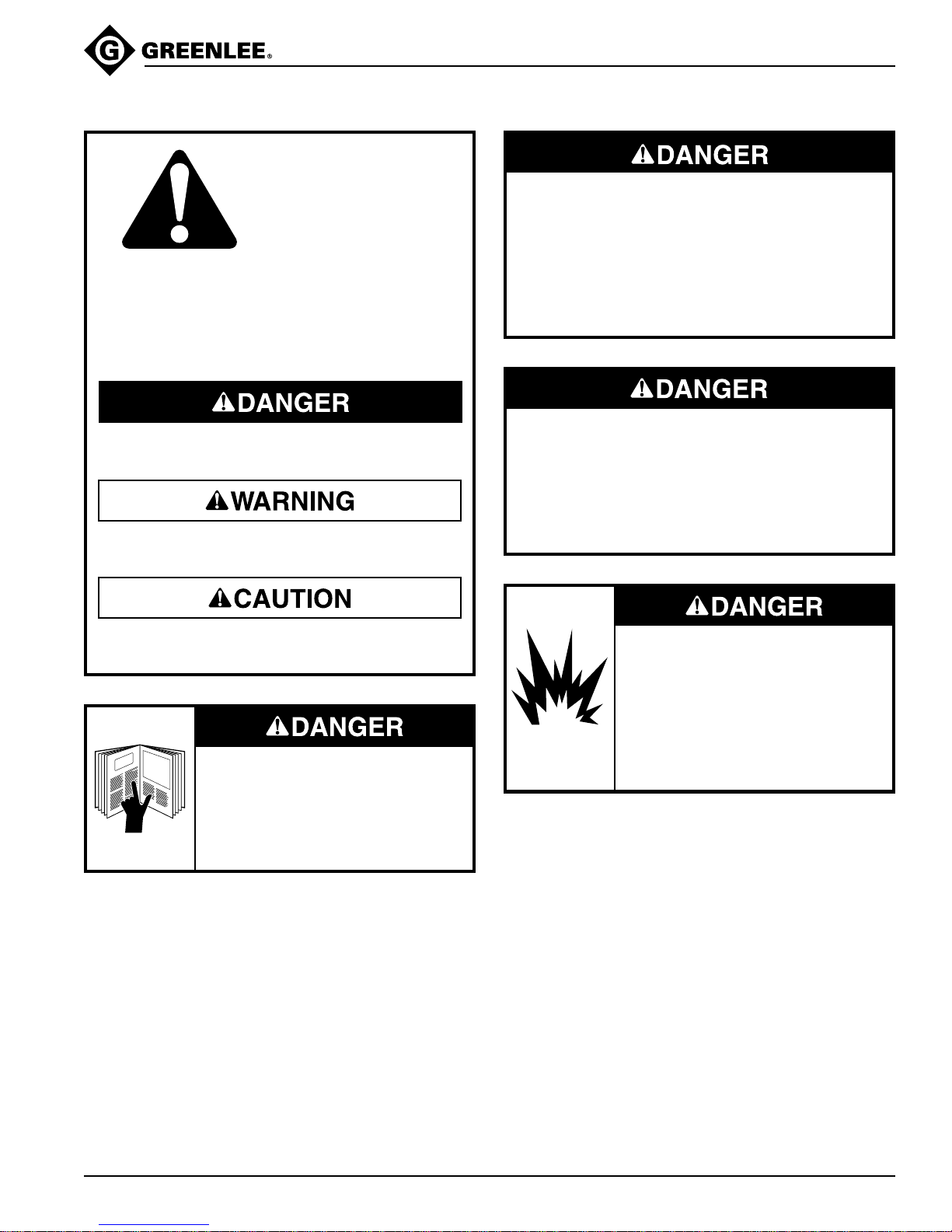
This symbol is used to call your attention to hazards
or unsafe practices which could result in an injury or
property damage. The signal word, defined below,
indicates the severity of the hazard. The message
after the signal word provides information for
preventing or avoiding the hazard.
960 PS Series Hydraulic Power Pumps
Do not connect the pump to any system or system
component other than those supplied by Greenlee.
Other manufacturers’ components may not withstand
the maximum pressure and may fail. Nearby
personnel can be injured by flying components and
hydraulic oil.
Failure to observe this warning will result in severe
injury or death.
Immediate hazards which, if not avoided, WILL
result in severe injury or death.
Hazards which, if not avoided, COULD result in
severe injury or death.
Hazards or unsafe practices which, if not avoided,
MAY result in injury or property damage.
Read and understand all of the
instructions and safety information in
this manual before operating or
servicing this tool.
Failure to observe this warning will
result in severe injury or death.
Do not alter the internal high-pressure relief valve
setting. Altering this setting will change the maximum
pressure the pump can develop, which can cause a
component failure. Nearby personnel can be injured
by flying components and hydraulic oil.
Failure to observe this warning will result in severe
injury or death.
Do not use this pump in a hazardous
environment. Hazards include
flammable liquids, gases, or other
materials. Using this pump in a
hazardous environment can result in
a fire or explosion.
Failure to observe these warnings
will result in severe injury or death.
Greenlee / A Textron Company 3 4455 Boeing Dr. • Rockford, IL 61109-2988 USA • 815-397-7070
Page 4
960 PS Series Hydraulic Power Pumps
IMPORTANT SAFETY INFORMATION
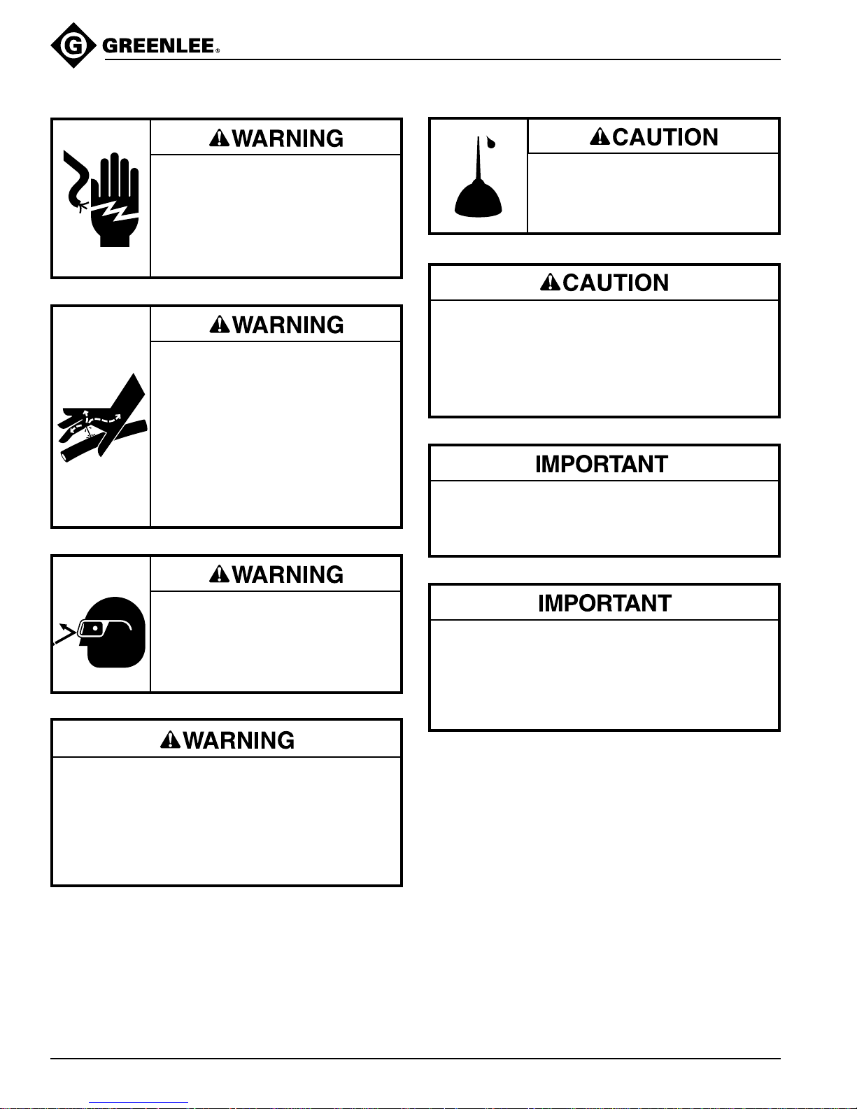
Electric shock hazard:
• Do not expose power tools to rain.
• Do not immerse the pendant
switch in water or other liquid.
Failure to observe these warnings
can result in severe injury or death.
Skin injection hazard:
Oil under pressure easily punctures
skin, causing serious injury, gangrene,
or death. If injured, seek medical
help immediately to remove oil.
• Do not use hands to check for
leaks.
• Depressurize the hydraulic system
before servicing or disconnecting
the hose.
Fill unit with hydraulic oil before
operating pump.
Failure to fill unit with oil will result in
damage to the pump.
• The pump is heavy and requires two persons to
lift. Improper lifting can result in injury.
• Do not use hose or cord to pull, lift, or carry the
equipment. Misuse will damage the hose or cord.
Failure to observe these precautions can result in
injury or property damage.
Make sure all hose fittings are properly seated
before starting the pump. Incomplete connections
may not allow the accessory’s ram to retract after
the hydraulic operation is finished.
Wear eye protection when operating
or servicing this tool.
Failure to wear eye protection can
result in serious eye injury from
flying debris or hydraulic oil.
Inspect pump, hoses, couplers, and fittings for
wear or damage. Replace worn, damaged, or
missing components with Greenlee replacement
parts. Worn or damaged components can fail,
resulting in injury.
Failure to observe this warning can result in
severe injury or death.
Procedure for depressurizing the hydraulic system:
1. Disconnect the pump from the power source.
2. Rotate the release lever clockwise.
3. Disconnect the hose slowly to release any
trapped pressure.
Note: Keep all decals clean and legible, and replace
when necessary.
Greenlee / A Textron Company 4 4455 Boeing Dr. • Rockford, IL 61109-2988 USA • 815-397-7070
Page 5

Specifications
Capacities
Pumping Capacity at 6.89 bar (100 psi) .............................. 4.92 l/min (300 in3/min)
Pumping Capacity at 689 bar (10,000 psi) ........................... 0.98 l/min (60 in3/min)
Reservoir Capacity ................................................................................... 7.5 l (8 qt)
Usable Oil Volume ............................................................................... 5.9 l (6.25 qt)
Duty Cycle
0 bar to 413.7 bar (0 psi to 6000 psi)................................................ continuous use
413.7 bar to 689.5 bar (6000 psi to 10,000 psi)................................intermittent use
Power Source...................................................................................... 115 VAC, 60 Hz
Dimensions
Length..................................................................................................30.5 cm (12")
Width...............................................................................................26.75 cm (10.5")
Height ..................................................................................................65 cm (25.5")
Weight/Mass ......................................................................................... 42 kg (92 lb)
960 PS Series Hydraulic Power Pumps
(this limitation is for motor protection only)
Greenlee Hydraulic Oil (Mobil DTE
Part No. 905 1059.3 / 4016GB .....................................................................1 gallon
Part No. 905 0806.8 / 4017GB ...................................................................... 1 quart
Abbreviations
SA Single Action Valve, Greenlee Part No. 501 5644.6
PS Pendant Switch, Greenlee Part No. 503 2363.6
PSL Pendant Switch, Los Angeles County
(specifically wired and labeled to meet the electrical code
of Los Angeles County, CA)
®
13M)
Greenlee / A Textron Company 5 4455 Boeing Dr. • Rockford, IL 61109-2988 USA • 815-397-7070
Page 6
Setup
960 PS Series Hydraulic Power Pumps
Hydraulic Connection
1. Clean all couplers, threaded fittings, and ports.
2. Remove any dust plugs from couplers.
3. Hand-tighten all couplers firmly. Do not use tools.
4. Install hydraulic oil. Refer to the “Specifications”
section of this manual to determine the correct type
of hydraulic oil.
Electrical Connection
Electric shock hazard:
• Do not modify the plug provided
with the tool.
• Connect this tool to a grounded
receptacle on a 15-amp GFCIprotected circuit.
Failure to observe these warnings
can result in severe injury or death.
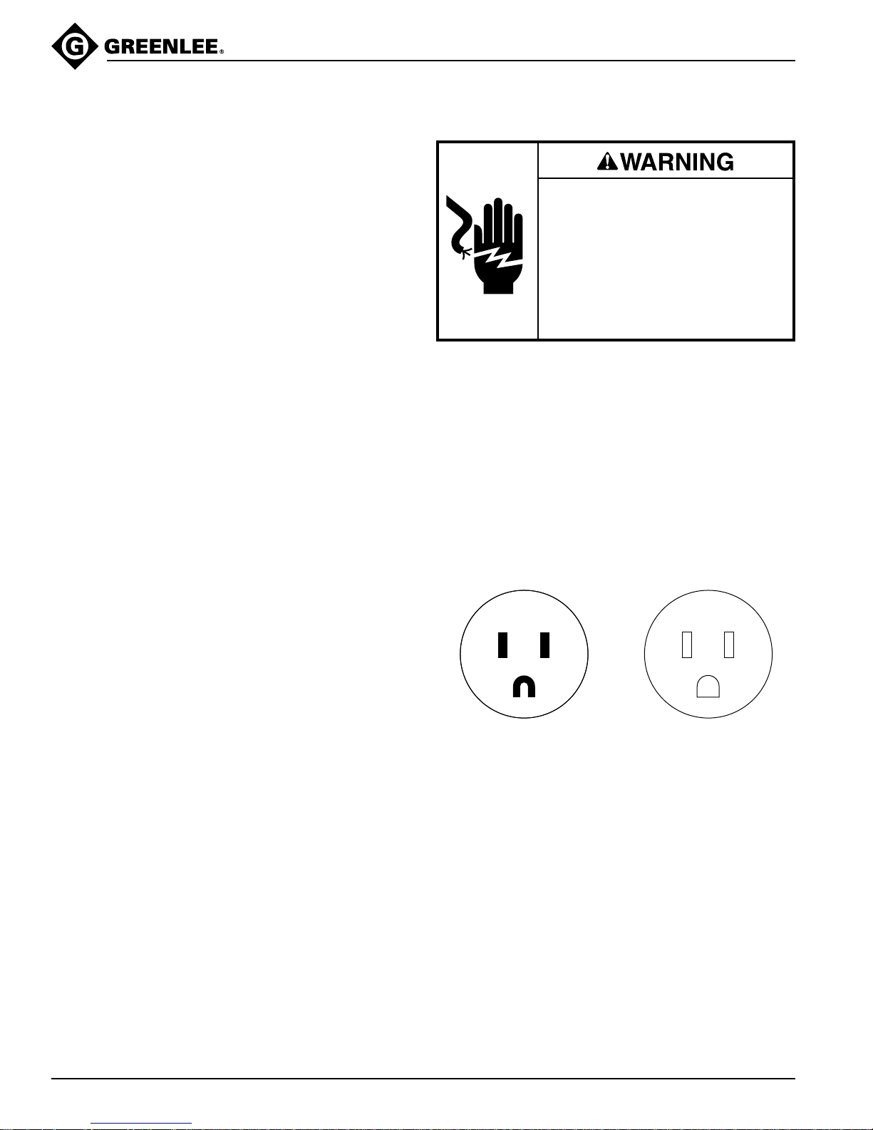
This tool must be grounded. In the event of a malfunction or breakdown, an electrical ground provides a path
of least resistance for the electric current. This path of
least resistance is intended to reduce the risk of electric
shock.
This tool’s electric cord has a grounding conductor and a
grounding plug as shown. Do not modify the plug.
Connect the plug to a corresponding 15-amp GFCI
protected receptacle that is properly installed and
grounded in accordance with all national and local codes
and ordinances.
Do not use an adapter.
Greenlee / A Textron Company 6 4455 Boeing Dr. • Rockford, IL 61109-2988 USA • 815-397-7070
ReceptaclePlug
Extension cord specifications:
Diameter ....................................... 2.5 mm
Length..................................................... 30 m (100 ft)
Use only three-wire extension cords. Use of an
inadequate extension cord will cause the motor to stall.
2
(12 AWG)
Page 7
Motor Wiring Diagram
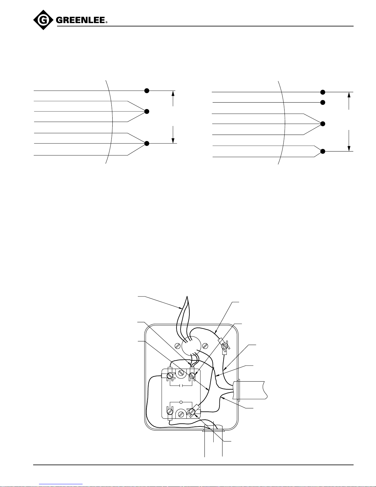
CONNECTIONS FOR CW ROTATION (VIEW FROM LEAD END OF MOTOR)
960 PS Series Hydraulic Power Pumps
Franklin GE
Brown (10)
Violet (9)
Pink (1)
Orange (5)
Red (8)
Blue (4)
Black (2)
Purple P1
Brown P2
Black T5
Orange T3
Red J10
White T2
Yellow T4
LOW VOLTAGE
Low
Voltage
Line
The 960 pump is equipped with a NEMA 5-15 plug for
connection to a standard outlet on a 115-volt, 15-amp,
60 Hz, single-phase circuit.
The PSL models are specifically wired and labeled
to meet the electrical code of Los Angeles County,
California. They are equipped with a NEMA 5-20 plug for
connection to a NEMA 5-20 receptacle on a 115-volt,
15-amp, 60 Hz, single-phase circuit.
For operation at 230 volts, Greenlee suggests returning
the pump to the factory.
Franklin GE
Brown (10)
Violet (9)
Pink (1)
Blue (4)
Orange (5)
Red (8)
Black (2)
Purple P1
Brown P2
Black T5
White T2
Orange T3
Red J10
Yellow T4
HIGH VOLTAGE
(R3)(R3)
Insulate This Lead
High
Voltage
Line
(R2)(R2)
To convert the pump to 230-volt operation:
• Re-wire the unit according to the wiring diagram that
corresponds to the motor on your pump. Then replace
the plug with a NEMA 6-15 plug.
• Solid state relay (Part No. 918 6403.8), motor, switch,
and all other components are suitable for 230-volt
operation.
Note: Greenlee will not be held liable for injuries or
damage resulting from re-wiring the pump.
F.E.
ORANGE
VIOLET
PINK
BLACK
BLUE
RED
BROWN
G.E.
ORANGE
BROWN
BLACK
YELLOW
WHITE
RED
PURPLE
R1
R4
• Occasionally check oil temperature after pump is
operated. The recommended operating temperature
is 38 °C to 50 °C (100 °F to 125 °F).
MTR GRD
GRN
2x #8-32
MOTOR
R2
R3
GRD
GRN
L1
BLK
LINE
L2
WHT
Greenlee / A Textron Company 7 4455 Boeing Dr. • Rockford, IL 61109-2988 USA • 815-397-7070
PENDANT
SWITCH
2x #6-32
Page 8
Operation
960 PS Series Hydraulic Power Pumps
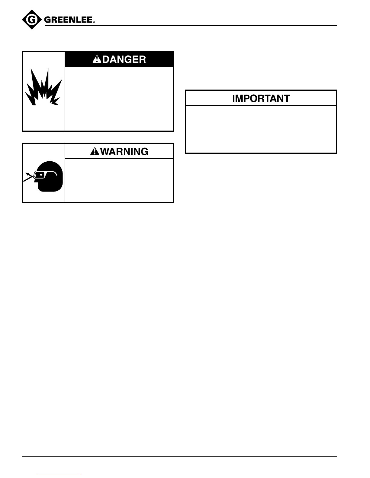
Do not use this pump in a hazardous
environment. Hazards include
flammable liquids, gases, or other
materials. Using this pump in a
hazardous environment can result in
a fire or explosion.
Failure to observe these warnings
will result in severe injury or death.
Wear eye protection when operating
or servicing this tool.
Failure to wear eye protection can
result in serious eye injury from
flying debris or hydraulic oil.
Changing Accessories
Before changing the hydraulic accessory that is
connected to the pump, follow this procedure for
depressurizing the system.
Procedure for depressurizing the hydraulic system:
1. Disconnect the pump from the power source.
2. Rotate the release lever clockwise.
3. Disconnect the hose slowly to release any
trapped pressure.
Note: Starting the motor without a tool attached to the
pump will cause the pump to immediately build an
internal pressure of 689.5 bar (10,000 psi).
If this happens, shut off the pump and turn the valve
lever clockwise to release the hydraulic pressure.
1. Move release valve lever clockwise.
2. Check reservoir oil level. The oil level should be
within 13 mm (1/2") of the top of the reservoir.
If oil level is too low, refer to “Adding Oil” under
“Maintenance and Service” in this manual.
3. Turn the dipstick two turns counterclockwise.
Note: Operating the pump without loosening the
dipstick will result in poor pump performance.
4. Connect the pump to an appropriate power supply.
5. Start motor and allow pump to idle for a few minutes.
This will allow the hydraulic fluid to work through the
system and prime the pump.
6. Stop the motor. Turn the lever counterclockwise.
7. Start the motor to advance the hydraulic ram. When
finished, stop the motor. Turn the lever clockwise to
release the pressure.
Note: Starting the pump while the lever is in the
clockwise position may cause the ram to extend.
Turning the lever counterclockwise while the pump is
running may release the pressure.
8. During periods of heavy use, occasionally stop the
pump and check the oil temperature. The recommended operating temperature is 38 °C to 50 °C
(100 °F to 125 °F).
9. Tighten the dipstick.
Greenlee / A Textron Company 8 4455 Boeing Dr. • Rockford, IL 61109-2988 USA • 815-397-7070
Page 9
Maintenance and Service
960 PS Series Hydraulic Power Pumps
Maintenance Schedule
Every time the pump is used:
• Check the oil reservoir level. The oil level should be
approximately 13 mm (1/2") from the top of the reservoir. If the oil level is low, refer to “Adding Oil” in this
section of this manual.
• Listen for unusual noises and observe the operation of
the pump for changes in performance. Either situation
may indicate that maintenance or repairs
are necessary.
Periodically:
Examine the hydraulic oil for changes in color or viscosity,
and the presence of dirt or other contamination.
Cleaning
• Periodically clean the exterior of the pump and motor.
Use a vacuum cleaner to clean the ventilation open-
ings.
• Clean the area around the reservoir vent, and be sure
the vent breather hole is open.
• Keep all hose connections clean and use protective
caps or plugs when couplers are not in use.
Inspecting Oil
Inspect the oil occasionally. A change in appearance,
such as darkening or thickening, indicates that the oil
needs to be replaced. Continued use of the oil after it
should be replaced will cause accelerated wear of
system components and will void the warranty.
Adding Oil
Do not use brake fluid. Brake fluid will ruin the seals.
Refer to the “Specifications” section of this manual to
determine the correct type of hydraulic oil and Greenlee
part number.
1. Rotate the valve lever in the clockwise position.
2. Disconnect the pump from the power supply.
3. Clean the area around the fill hole.
4. Remove the reservoir pipe plug.
5. Use Greenlee hydraulic fluid or an equivalent high
grade light hydraulic oil. Refer to “Specifications” in
this manual.
6. Pour the oil through a clean funnel with a filter
screen.
7. Add oil until the oil level is within 13 mm (1/2") from
the reservoir cover.
8. Replace the pipe plug.
Purging (Bleeding) Air from the System
Erratic performance may be caused by air in the
hydraulic fluid.
Note: Position the pump so that it is above the
accessory. Position the accessory so the hose
connection is upward. This will allow any air in the
accessory to escape into the hose and travel upward to
the pump reservoir.
1. Remove any items (conduit, cable, etc.) from the
hydraulic accessory.
2. Rotate the valve clockwise.
3. Turn the dipstick two turns counterclockwise.
4. Connect the pump to an appropriate power supply.
5. Start the hydraulic pump and advance the ram
(hydraulic cylinder) of the accessory to a full stroke
and repeat several times. Stop pump and rotate
valve clockwise to retract ram. As the ram retracts,
the oil in the hose will return to the reservoir in the
pump.
Draining and Flushing the System
1. Thoroughly clean the pump exterior.
2. Remove the motor mounting plate screws.
3. Remove the pump system from the reservoir.
Note: Do not damage the motor mounting plate
gasket, intake screen, or relief valve when removing
the pump.
4. Clean the interior of the reservoir and fill with clean
kerosene. Do not use solvents.
5. Rinse the intake screen.
6. Place the pump system into the reservoir and
replace the motor mounting plate screws.
7. Connect a hose to the pump. Insert the other end of
the hose into the pump reservoir at the fill hole.
8. Run the pump for a few minutes. While the pump
is running, rotate the control lever several times.
Start and stop the pump several times to cycle the
unloading valve.
Note: Do not operate pump for more than a few
minutes as system is not designed to operate with
kerosene.
9. Remove the hose and pump assembly from the
reservoir. Drain and clean the reservoir interior.
Allow the reservoir to dry.
10. Reassemble the pump system.
11. Fill the reservoir. Refer to “Adding Oil” in this section
of the manual.
Motor Maintenance
When repairs are necessary, send the motor to one of
the motor manufacturer’s authorized service stations.
Greenlee / A Textron Company 9 4455 Boeing Dr. • Rockford, IL 61109-2988 USA • 815-397-7070
Page 10
Troubleshooting
960 PS Series Hydraulic Power Pumps
Problem Probable Remedy
Motor does not run. Voltage supplied is too low, Check the voltage at the power supply.
or no power at outlet. Refer to the “Specifications” section of this
Extension cord is too long or wire Use a shorter or heavier gauge
gauge is too light. extension cord.
Relay is faulty. Replace relay (63).
Motor is faulty. Repair or replace motor.
Pump develops little pressure Oil level is low. Check oil level. Refer to “Adding Oil” in this
(low-pressure system failure). manual.
Clogged intake screen. Clean or replace intake screen (24).
Faulty low-pressure relief valve. Replace valve (2).
Faulty low-pressure system. Repair low-pressure system. Purchase
Probable Cause
manual for required voltage.
Vane Repair Kit. Refer to the repair kits at
the end of the parts list.
Pump develops substantial Low-pressure system failure. Refer to the causes and remedies described
pressure, but doesn’t complete under low-pressure system failure.
the hydraulic operation (highpressure system failure). Faulty high-pressure relief valve. Replace valve (1).
Sticking plunger. Replace plunger (8) and bushing (9).
Leaking ball. Re-finish the seats for the 9/32" balls.
Replace the 9/32" balls (26).
Sticking low pressure plunger. Replace plunger (19).
Pressure buildup is erratic. Oil level is low. Check oil level. Refer to “Operation” in
this manual.
Air in hydraulic system. Refer to “Purging (Bleeding) Air from the
System.”
Dirt in the hydraulic system. Refer to “Draining and Flushing
the System.”
Faulty high-pressure relief valve. Replace valve (1).
Sticking plunger. Replace plunger and bushing (8, 9).
Greenlee / A Textron Company 10 4455 Boeing Dr. • Rockford, IL 61109-2988 USA • 815-397-7070
Page 11
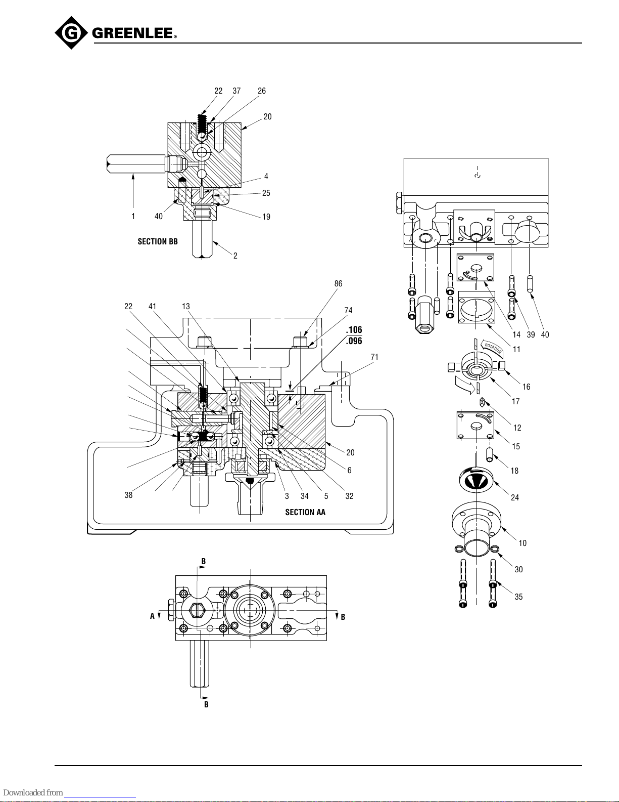
Illustration
;;
;
;;
960 PS Series Hydraulic Power Pumps
22 37 26
20
4
25
401
SECTION BB
22 41 13
8
9
33
7
26
29
36
23
38 28
4
19
2
86
74
.106
.096
71
R
O
T
A
T
I
O
N
14 39 40
11
16
17
12
20
6
334 5 32
15
18
24
SECTION AA
B
A
Greenlee / A Textron Company 11 4455 Boeing Dr. • Rockford, IL 61109-2988 USA • 815-397-7070
10
30
35
B
B
Page 12
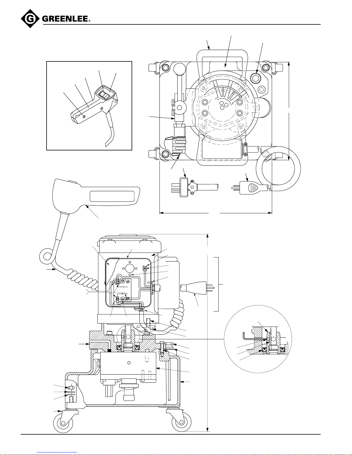
Illustration
960 PS Series Hydraulic Power Pumps
SERIAL NO. LOCATION
68
73
95
96
97
52 PENDANT
98
99
E
89
78
12.00
52
62
10.50
59
94
55
56
63 57, 58, 65
69
84
82
83
81
60
1
4
GREEN
2
BLACK
WHITE
3
WHITE
BLACK
85
56
54
61
64
53
76
74
66
77
75
A
67
22.59
960 SERIES
62
C or D
92
1/8 ALLEN
WRENCH
80
70
72
Item #92 is threaded onto Item #13.
To remove, place a long bolt through
the hole in the side of the pump block.
Rotate the eccentric until the screw
acts as a stop. Use a wrench to loosen
#92 from #13.
Greenlee / A Textron Company 12 4455 Boeing Dr. • Rockford, IL 61109-2988 USA • 815-397-7070
Page 13

Parts List
960-SA-PS consists of A, C, E, 2, 66–86, and 92
Key Part No. Description Qty
A 501 8236.6 Block unit, pump (includes items 1 and 3–41)................................... 1
C 502 0721.0 Cord unit, PS power and enclosure with 15-amp plug
(includes items 52–65) ...................................................................... 1
D 501 8477.6 Cord unit, PSL power and enclosure with 20-amp plug
(includes items 52–65 and 89) .......................................................... 1
E 501 5644.6 Single-action valve for -SA series pumps.......................................... 1
F Twin-action valve for -TA series pumps ............................................ 1
Subplate for TA valve ........................................................................ 1
1 500 6067.8 Valve unit, high pressure relief.......................................................... 1
2 501 7766.4 Valve unit, low pressure relief ........................................................... 1
3 501 8194.7 Plate, pump mounting ....................................................................... 1
4 500 3493.6 Pin, seal, .125 x .500......................................................................... 1
5 501 8871.2 Spacer, .790 x 1.62 x .187 ................................................................ 1
6 501 1855.2 Race, outer........................................................................................ 1
7 501 1862.5 Plug, plunger, high pressure ............................................................. 1
8 501 9060.1 Plunger, high pressure ...................................................................... 1
9 501 9059.8 Bushing, plunger, high pressure ....................................................... 1
10 502 0424.6 Block, intake...................................................................................... 1
11 501 4861.3 ** Plate, pump ....................................................................................... 1
12 501 4862.1 ** Key, square, .125 x .375 ................................................................... 1
13 501 4876.1 Shaft, eccentric.................................................................................. 1
14 501 7130.5 ** Plate, top........................................................................................... 1
15 501 7131.3 ** Plate, bottom..................................................................................... 1
16 501 7135.6 ** Vane, pump....................................................................................... 4
17 501 7136.4 ** Rotor.................................................................................................. 1
18 501 7467.3 Dowel, hollow .................................................................................... 1
19 501 8195.5 Plunger, check valve ......................................................................... 1
20 501 8237.4 Block, pump....................................................................................... 1
22 500 6111.9 * Spring, compression, .219 x .281 x .875 ........................................... 1
23 501 4865.6 * Spring, compression, .225 x .281 x .656 ........................................... 1
24 502 1175.7 Screen, intake ................................................................................... 1
25 905 0014.8 * O-ring, 5/8 x 3/4 x 1/16 ...................................................................... 1
26 905 0436.4 * Ball, steel, 9/32 diameter ................................................................... 2
28 905 0677.4 * Ball, steel, 5/32 diameter ................................................................... 1
29 905 0681.2 * Ball, steel, 3/8 diameter ..................................................................... 1
30 905 1526.9 Washer, lock, .172 x .267 x .045 spring ............................................ 4
32 502 2611.8 Roller, .125 x .750 Torrington (set of 30 rollers)................................ 1
33 905 1524.2 * O-ring, 1/2 x 5/8 x 1/16 ...................................................................... 1
34 905 0989.7 Bearing, ball, .787 x 2.04 x .590........................................................ 1
35 905 0994.3 Screw, cap, #8–32 x 1.25 socket head ............................................. 4
36 905 1111.5 Screw, set, 7/16–20 x .500 socket head ........................................... 1
37 905 2817.4 * O-ring, 7/16 x 9/16 x 1/16 .................................................................. 1
38 905 1241.3 Screw, set, #10–32 x .187 socket flat point....................................... 1
39 905 1471.8 Screw, cap, #10–32 x .875 socket head ........................................... 6
40 905 1472.6 Pin, dowel, .250 x .750...................................................................... 2
41 905 1473.4 Bearing, ball, .984 x 2.04 x .590........................................................ 1
52 503 2363.6 Switch unit, pendant (includes items 94 – 98)................................... 1
53 918 5117.3 Connector, two screw........................................................................ 2
54 905 3194.9 Screw, self-tapping, #10–16 x .250 Phillips head.............................. 1
55 918 5287.0 Terminal, flanged fork........................................................................ 2
56 918 5757.0 Terminal, locking fork ........................................................................ 3
57 905 0633.2 Nut, hex, #8-32.................................................................................. 2
960 PS Series Hydraulic Power Pumps
Greenlee / A Textron Company 13 4455 Boeing Dr. • Rockford, IL 61109-2988 USA • 815-397-7070
Page 14

Parts List (cont’d)
Key Part No. Description Qty
58 905 0685.5 Washer, lock, #8................................................................................ 2
59 503 5912.6 Cover, relay enclosure ...................................................................... 1
60 503 6049.3 Base, relay enclosure........................................................................ 1
61 905 3281.3 Screw, self-tapping, #10–16 x .625 Phillips head.............................. 2
62 918 6074.1 Cord, electric ..................................................................................... 1
63 918 6403.8 Relay, solid state ............................................................................... 1
64 905 2240.0 Screw, self-tapping, #6–20 x .375 Phillips head................................ 2
65 905 1440.8 Screw, machine, #8-32 x .375 round head........................................ 2
66 501 5646.2 Dip stick............................................................................................. 1
67 501 5695.0 Reservoir ........................................................................................... 1
68 501 2663.6 Handle, lifting..................................................................................... 2
69 501 8292.7 Plate, motor mounting ....................................................................... 1
70 501 4852.4 Key, motor shaft (supplied with motor).............................................. 1
71 501 5701.9 * Gasket, reservoir............................................................................... 1
72 905 0320.1 * Seal, oil, 1.37 x 2.37 x .312............................................................... 1
73 905 0734.7 Plug, pipe, 3/4, NPTF socket ............................................................ 1
74 905 0506.9 Washer, lock, 3/8............................................................................... 8
75 905 0522.0 Screw, cap, 5/16–18 x. 1.00 hex head.............................................. 3
76 905 0532.8 Screw, cap, 3/8–16 x. 1.25 hex head................................................ 4
77 905 0387.2 * O-ring, 7/16 x 5/8 x 3/32.................................................................... 1
78 905 0807.6 Coupler, quick, 3/8" (TAPS model has quantity of 2) ........................ 1
80 905 1269.3 Screw, set, 1/4–20 x. 250 socket head ............................................. 1
81 905 1428.9 Caster, swivel.................................................................................... 4
82 905 2836.0 Washer, shakeproof, 3/8 ................................................................... 8
83 905 1434.3 Washer, flat, 13/32 x 13/16 x 1/16 .................................................... 4
84 905 1435.1 Nut, hex, 3/8–16................................................................................ 4
85 Motor unit (refer to the “Motor Parts List”) ......................................... 1
86 905 1474.2 Screw, cap, 3/8–24 x. 2.50 socket head ........................................... 4
89 918 5558.6 Plug, 3-wire, 125 V, 20 amp .............................................................. 1
92 501 8238.2 Adapter, drive shaft ........................................................................... 1
94 503 2362.8 Cord unit............................................................................................ 1
95 501 3901.9 Handle, left half ................................................................................. 1
96 503 1902.7 Handle, right half ............................................................................... 1
97 905 3441.7 Screw, self-tapping, #6–20 x .625 pan head..................................... 3
98 918 6189.5 Switch, rocker, single-pole, momentary ON ...................................... 1
Decals
99 503 2370.9 Decal, face plate (ON/OFF)............................................................... 1
Repair Kits
960 PS Series Hydraulic Power Pumps
501 2121.9 Decal, Greenlee safety...................................................................... 1
501 2214.2 Decal, caution.................................................................................... 1
501 5832.5 Decal, arrow ...................................................................................... 1
500 7248.6 Decal, extension cord........................................................................ 1
502 1366.0 Decal, vent caution............................................................................ 1
502 1395.4 Tag, vent caution............................................................................... 1
503 4316.5 Decal, read IM ................................................................................... 1
503 5031.5 Decal, nameplate .............................................................................. 1
503 2370.9 Decal, face plate................................................................................ 1
503 5472.8 Decal, schematic ............................................................................... 1
500 2581.3 Decal, caution.................................................................................... 1
502 2510.3 Decal, caution.................................................................................... 1
501 8416.4 Kit, packing repair (includes all items with *)
502 0697.4 Kit, vane repair (includes all items with **)
503 5476.0 Kit, relay replacement (convert from mechanical relay to solid state relay)
501 8443.1 Enclosure, relay (includes 59, 60, and 64)
501 8280.3 Caster set
Greenlee / A Textron Company 14 4455 Boeing Dr. • Rockford, IL 61109-2988 USA • 815-397-7070
Page 15

960 PS Series Hydraulic Power Pumps
Motor Parts List
Motors from General Electric, Franklin Electric, and Dayton have been used on this series of pumps.
To identify the motor, refer to the manufacturer’s name, part number and description on the motor nameplate.
Motor, 1-1/2 HP @ 3600 RPM, 115/230 VAC, 60 Hz, Single Phase
Greenlee Part No. G. E. Part No. Description Qty
* 918 5300.1 5KC48SG332T Motor ..........................................................................1
918 5351.6 8753704AZP20 Capacitor.................................................................... 1
918 5356.7 111B277AAP1 Cover, cap ..................................................................1
918 5726.0 114A882AAGT Fan ............................................................................. 1
918 5361.3 114C922AAP1 Canopy cover, fan...................................................... 1
Greenlee Part No. Franklin Part No. Description Qty
* 918 5300.1 Motor ..........................................................................1
918 6550.6 275464-132 Capacitor ....................................................................1
918 6551.4 276856-101 Cover, cap ..................................................................1
918 6552.2 296114-101 Fan .............................................................................1
918 6553.0 297673-102 Canopy cover, fan ......................................................1
Motor, 1-1/2 HP @ 3600 RPM, 115/230 VAC, 60 Hz, Single Phase
Greenlee Part No. G. E. Part No. Description Qty
918 5466.0 5KC48SG573T Motor ..........................................................................1
918 5466.0 5KC48SG952T Motor ..........................................................................1
918 5701.5 111A277P1 Capacitor ....................................................................1
918 5356.7 111B277AAP1 Cover, cap ..................................................................1
918 5726.0 114A882AAG7 Fan ............................................................................. 1
918 5361.3 114C922AAP1 Canopy cover, fan...................................................... 1
Greenlee Part No. Franklin Part No. Description Qty
918 5466.0 113007420 Motor .......................................................................... 1
918 6550.6 275464-132 Capacitor ....................................................................1
918 6551.4 276856-101 Cover, cap ..................................................................1
918 6552.2 296114-101 Fan .............................................................................1
918 6553.0 297673-102 Canopy cover, fan ......................................................1
Motor, 1 HP @ 1800 RPM, 115/230 VAC, 60 Hz, Single Phase
Greenlee Part No. G. E. Part No. Description Qty
918 5183.1 5KC43PG782T Motor ..........................................................................1
918 5349.4 8753704AX16 Capacitor ....................................................................1
918 5353.2 118276AAP1 Cover, cap .................................................................. 1
918 5389.3 114A882AAG1 Fan ............................................................................. 1
918 5361.3 114C922AAP1 Canopy cover, fan...................................................... 1
Greenlee Part No. Franklin Part No. Description Qty
918 5183.1 1112050101 Motor ..........................................................................1
918 6518.2 275463-102 Capacitor ....................................................................1
918 6519.0 290312-101 Cover, cap ..................................................................1
918 6552.2 296114-101 Fan .............................................................................1
918 6553.0 297673-420 Canopy cover, fan ......................................................1
Greenlee Part No. Dayton Part No. Description Qty
918 5183.1 6K674 Motor ..........................................................................1
918 6039.3 3R505 Capacitor.................................................................... 1
918 6040.7 2R831 Cover, cap.................................................................. 1
918 6041.5 2R901 Canopy cover, fan...................................................... 1
* 918 5300.1 can be replaced with 918 5466.0 on pendant switch unit.
Greenlee / A Textron Company 15 4455 Boeing Dr. • Rockford, IL 61109-2988 USA • 815-397-7070
Page 16
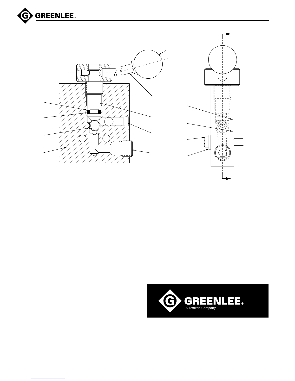
960 PS Series Hydraulic Power Pumps
SA Control Valve
11
5
10
2
A
13
1
4
3
6
7
12
8
9
SECTION A–A
Key Part No. Description Qty
1 501 0027.0 Handle unit, control ........................................................................... 1
2 501 5645.4 Block, control valve ........................................................................... 1
3 501 5705.1 Shaft, control valve............................................................................ 1
4 905 0168.3 O-ring, 3/8 x 1/2 x 1/16...................................................................... 1
5 905 0411.9 O-ring, 3/8 x 9/16 x 3/32.................................................................... 1
6 905 0418.6 O-ring, 1/4 x 3/8 x 1/16...................................................................... 1
7 905 0501.8 Plug, 1/8 pipe .................................................................................... 1
8 905 0807.6 Coupler, quick 3/8 ............................................................................. 2
9 905 0505.0 Washer, lock 5/16 x 9/16 x 1/16........................................................ 2
10 905 0714.2 Ball, steel 7/16................................................................................... 1
11 905 0747.9 Ring, backup 3/8 x 9/16 .................................................................... 1
12 905 1172.7 Screw, hex head cap, 5/16-24 x 1-1/2 .............................................. 2
13 905 0431.3 Knob.................................................................................................. 1
A
www.greenlee.com
Greenlee / A Textron Company 16 4455 Boeing Dr. • Rockford, IL 61109-2988 USA • 815-397-7070
USA (800) 435-0786 Fax: (800) 451-2632
(815) 397-7070 Fax: (815) 397-1865
Canada (800) 435-0786 Fax: (800) 524-2853
International +1 (815) 397-7070 Fax: +1 (815) 397-9247
4455 Boeing Drive, Rockford, IL 61109-2988 • USA • 815-397-7070
An ISO 9001 Company • Greenlee Textron is a subsidiary of Textron Inc.
Printed in USA
 Loading...