

Page 1
OPERATION, SERVICE AND PARTS
INSTRUCTION MANUAL
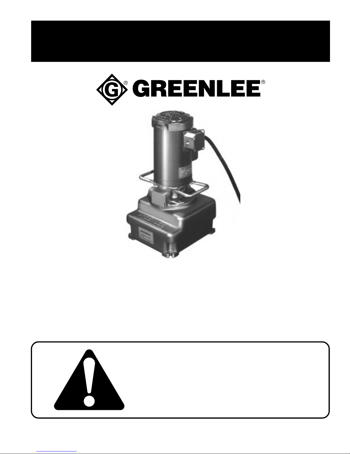
HYDRAULIC POWER PUMPS
940m3 & 960m3 SERIES
For all Pumps with Serial No. Code KR & KS
999 5279.3 © 1997 Greenlee Textron IM 855 REV 4 6/97
Read and understand this material before
operating or servicing this equipment. Failure
to understand how to safely operate this tool
could result in an accident causing serious
injury or death.
Page 2
Introduction
940m3 & 960m3 Series Hydraulic P o wer Pump
The 940M3and 960M3 Series are high pressure
hydraulic power pumps which are simple to operate,
lightweight, durable and portable.
These power pumps have a built-in high volume / low
pressure pumping feature which gives fast approach
ram action and automatic changeover to low volume /
high pressure when pressure exceeds 200 psi. The
pumping unit consists of a steel pump block, vaneoperated low-pressure stage, radially driven single-
SAFETY
ALERT
SYMBOL
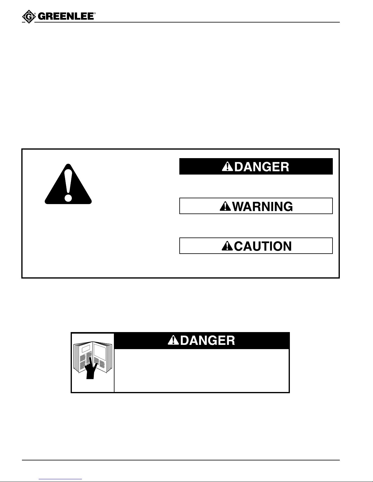
The symbol above is used to call your attention
to instructions concerning your personal safety.
Watch for this symbol. It points out important safety
precautions. It means “ATTENTION! Become alert!
Your personal safety is involved!” Read the
message that follows and be alert to the possibility
of personal injury or death.
piston high-pressure stage, high pressure safety valve
set at 10,000 psi, low pressure relief valve set at 200 psi
and an internally located relief valve which unloads the
high pressure stage of the pump and permits the motor
to be re-started while load is being held up to 10,000 psi.
The pump is controlled by a two-position toggle switch,
which has ON in the forward position, and OFF in the
opposite position.
Immediate hazards which, if not avoided, WILL result in
severe personal injury or death.
Hazards or unsafe practices which, if not avoided, COULD
result in severe personal injury or death.
Hazards or unsafe practices which, if not avoided, COULD
result in minor personal injury or property damage.
Safety is a critical factor in the design of Greenlee equipment. The best program starts with a safety-conscious
operator. The information highlighted in this bulletin describes operating practices for the benefit of the workers
who will use our equipment in their daily jobs. Comments from users are appreciated.
A person who has not read and does not understand all
operating instructions is not qualified to operate this tool.
Failure to read and understand safety instructions may
result in injury or death.
SA VE THESE INSTRUCTIONS
Additional copies of this manual are available upon request at no charge.
Greenlee Textron / Subsidiary of Textron Inc.
2
4455 Boeing Dr., Rockford, IL 61109-2988 815/397-7070
Page 3
940m3 & 960m3 Series Hydraulic P o wer Pump
IMPORTANT SAFETY INSTRUCTIONS
• Do not connect the pump to any system or
system component other than those supplied by
Greenlee and rated at less than 10,000 psi
(68,950 kPa).
• Do not alter the internal high-pressure relief
valve setting.
•
Do not use this pump in a hazardous environment.
Hazards include open flame and flammable liquids
or gases.
Failure to observe these warnings will result in
severe injury or death.
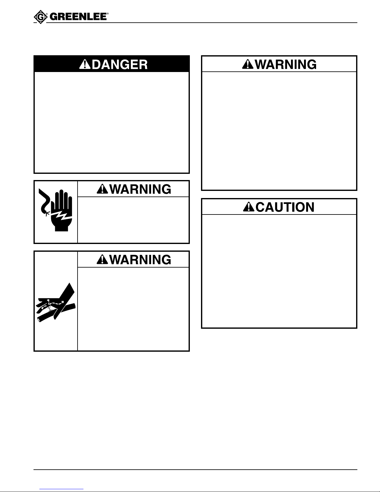
Electric shock hazard:
• Do not expose power tools to rain.
• Do not immerse the pendant
switch in water or other liquid.
Skin Injection Hazard:
High pressure oil easily punctures
skin causing serious injury, gangrene
or death. If injured seek medical help
immediately to remove oil.
Do not use fingers or hands to
check for leaks.
Depressurize hydraulic system
before disconnecting the hose.
•I
nspect pump, hoses, couplers and fittings for wear
or damage. Replace worn, damaged or missing
components with Greenlee replacement parts.
• Do not twist, kink, curl, paint or cut the
hydraulic hoses.
• Wear eye protection when operating this
equipment.
• Disconnect the pump from the power supply,
rotate the release valve lever to AUTO RELEASE,
and disconnect the hose from the ram and the
pump before performing any service.
Failure to observe these warnings could result in
severe injury or death.
• The pump is heavy, weighing up to 75 lbs. Follow
NIOSH work practices for manual lifting. If in
doubt, get help.
• Unplug pump when not in use and when changing
accessories.
• Do not use the hose to pull, lift, or carry the
equipment.
• Always work in an area providing good footing
and support.
• Keep work area well-lit, free of clutter, and dry.
Failure to observe these precautions could result in
injury or property damage.
Greenlee Textron / Subsidiary of Textron Inc.
3
4455 Boeing Dr., Rockford, IL 61109-2988 815/397-7070
Page 4
940m3 & 960m3 Series Hydraulic P o wer Pump
Assembly Instructions
These power pumps are completely assembled and are
shipped to you as a complete pumping unit. The only
assembly necessary is the connection of the ram to the
pump and the power cord to the proper electrical outlet.
Operating Instructions
The 940M3 and 960M3 power pumps are designed to
operate at 10,000 psi intermittently. For continuous
service, as production work, the pressure should not
exceed 6,000 psi. (This limitation is for motor protection
only.)
Before operating pump, check the following to assure
proper service:
1. Check for proper power connections and for tightness of hose connections before starting pump.
2. Check hydraulic oil with dipstick (52). Oil should be
within 1/2" of reservoir top.
3. Start motor and allow pump to idle a few minutes.
This will allow the hydraulic oil to work into the
moving parts and give prime to pump.
Power Connection
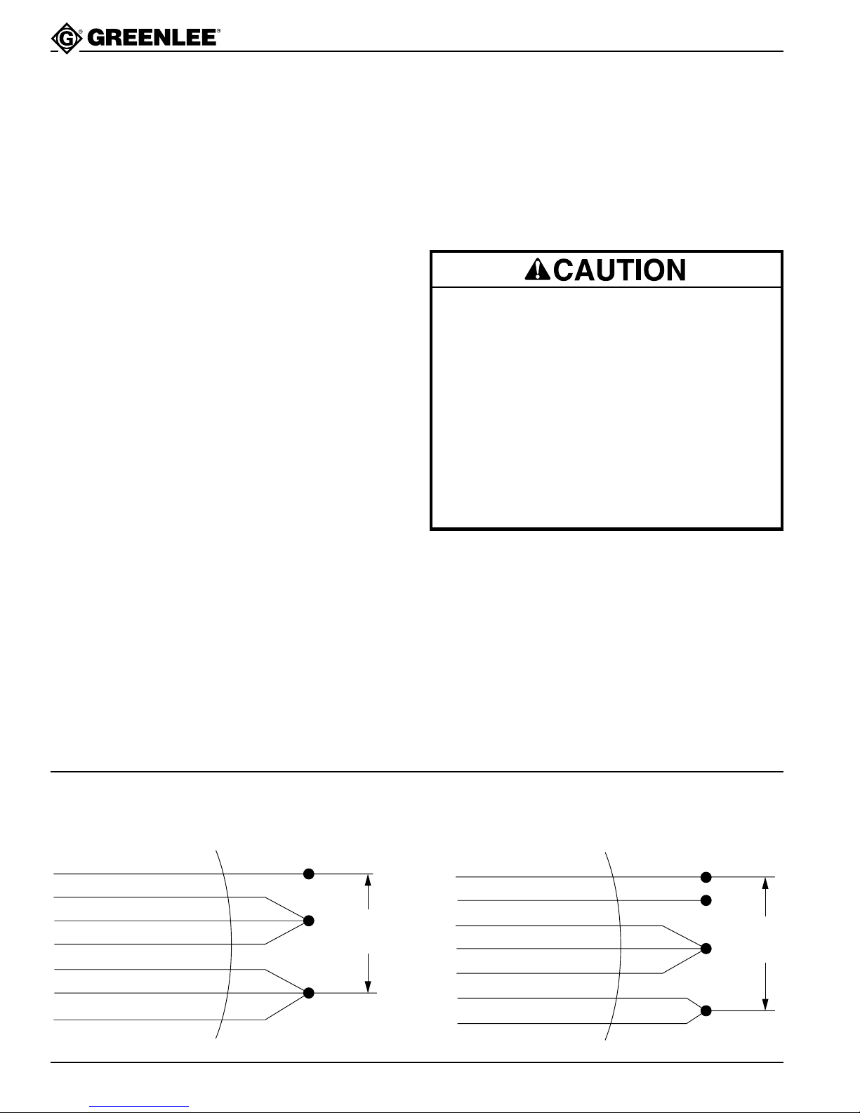
All power pumps shipped from Greenlee are wired for
115 volts, 60 Hz, Single Phase, AC operation unless
230-volt operation is requested at time of order. If 230volt operation is required at a later time, follow wiring
diagram for re-wiring.
Note: Greenlee will not be liable for any damage to a
pump or personal injury resulting from re-wiring
to a higher voltage.
For your protection, ground unit before using.
On the 940M3 and 960M3 Series pumps the
electric motor is equipped with an approved
3-conductor cord and 3-blade grounding-type
attachment plug to be used with the proper
grounding-type receptable, in according with the
National Electrical Code. The green-colored
conductor in the cord is the grounding wire,
which is attached to the metal frame of the unit
inside the housing and to the longest blade of
the attachment plug cap. (If extension cords are
used, they should have sufficient rated capacity
and a properly connected grounding circuit.)
Motor Wiring Diagram
CONNECTIONS FOR CW ROTATION (VIEW MOTOR FROM LEAD END)
Franklin GE
Brown (10)
Violet (9)
Pink (1)
Orange (5)
Black (2)
Red (8)
Blue (4)
Greenlee Textron / Subsidiary of Textron Inc.
Purple P1
Brown P2
Black T5
Orange T3
Yellow T4
Red J10
White T2
LOW VOLTAGE
Low
Voltage
Line
Franklin GE
Brown (10)
Violet (9)
Pink (1)
Orange (5)
Blue (4)
Red (8)
Black (2)
4
4455 Boeing Dr., Rockford, IL 61109-2988 815/397-7070
Purple P1
Brown P2
Black T5
Orange T3
White T2
Red J10
Yellow T4
HIGH VOLTAGE
Insulate This Lead
High
Voltage
Line
Page 5
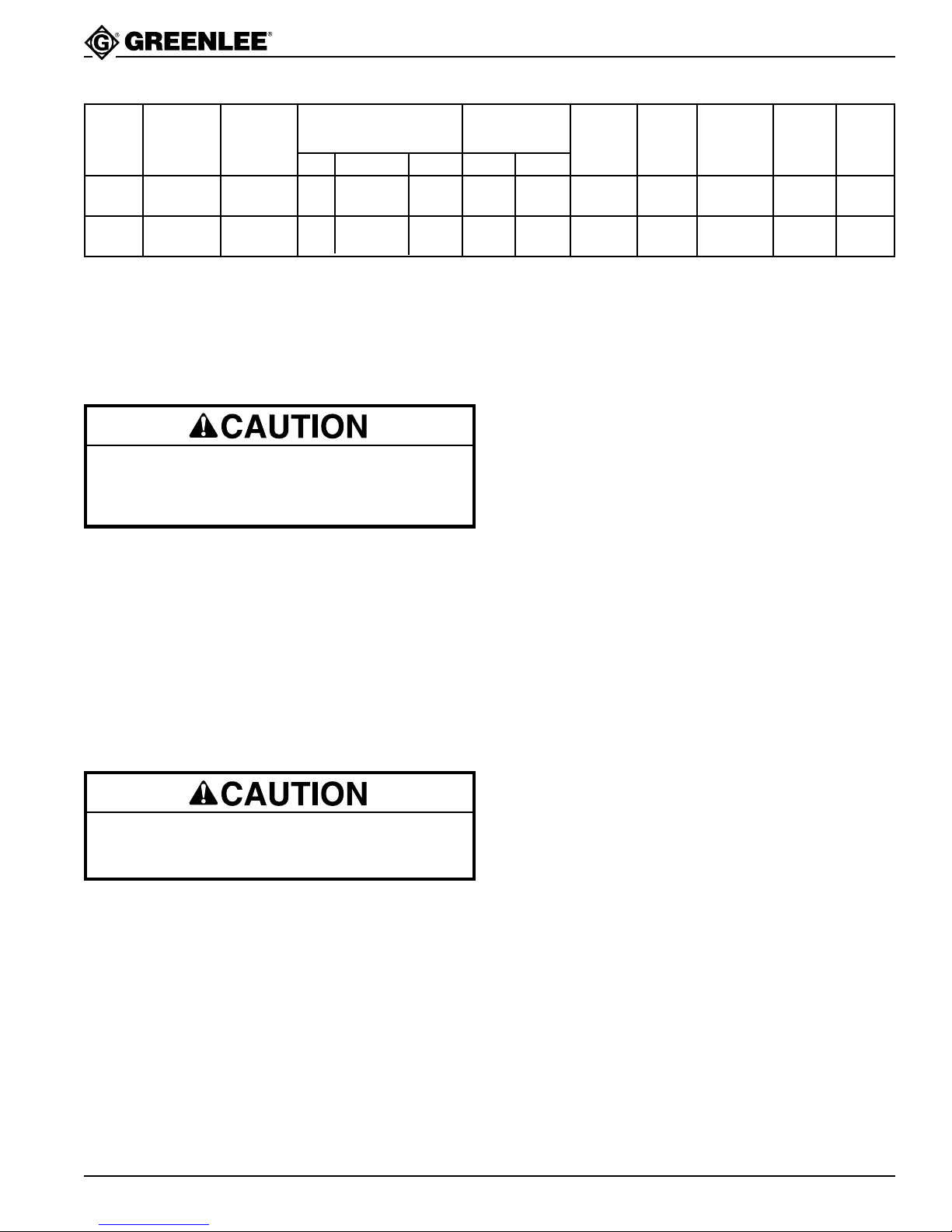
Pump Specifications
940m3 & 960m3 Series Hydraulic P o wer Pump
PUMP CONTROL CONTROL RESERVOIR USABLE APPROX.
MODEL NO. VALVE HEIGHT BASE CAPACITY OIL VOL. WT.
940m3
Basic
960m3
Basic
501.8348.6 Optional AC 1 (15 min.) 115/230 150 30 211/8"101/2 x 12 8 Qts. 6-1/4 Qts. 82#
501 8349.4 Optional AC 1
POWER SOURCE
TYPE H.P. VOLTS 100 PSI 10,000 PSI
1
/2 (15 min.) 115/230 300 60 2215/16"101/2 x 12 8 Qts. 6-1/4 Qts. 92 #
PUMPING CAPACITY
CU. IN./MIN.
QT.
Servicing Instructions
Filling Oil Reservoir. The oil reservoir must be kept
filled with a good grade of light hydraulic oil—Greenlee
905 0806.8 hydraulic oil or equal in order or the pump to
operate properly.
Never use synthetic fluids or fluids with poor
lubricating qualities, i.e., brake fluids, etc., as
permanent injury to the pump will result.
Eight quarts are required of which 6-1/4 quarts are
usable. A minimum of 1-3/4 quarts must be at the bottom
of the reservoir at all times during operation. Be sure
that your complete operation does not require more than
the usable amount of oil.
To refill or add oil to the reservoir, proceed as follows:
1. Remove vent unit from top of reservoir (B).
2. Add oil to within 1/2" of top of reservoir when ram is
retracted.
3. Install vent unit (B) securely in place.
Flushing System. As long as these pumps are used as
outlined in the operating instructions, long, trouble-free
performance can be expected. To maintain this performance, it is absolutely essential that dirt or other foreign
matter be kept out of the system as this is the most
common cause of hydraulic system failure. Therefore,
when opening up the pump for any reason, such as
making pipe connections, adjusting pressure or any
repair, be sure to exercise extreme care in cleanliness
and to use clean tools and cloths. If, at any time, dirt is
suspected to have found its way into the system, the
entire oil system should be flushed as follows:
1. Drain oil from reservoir.
2. Fill reservoir with any recommended flushing oil or
clean kerosene and operate pump. Work the control
handle back and forth several times during flushing
to wash all foreign particles from the control valve
unit.
Note: Do not operate pump for a very long time as
system is not designed to operate with flushing
oil or kerosene.
3. Drain flushing oil or kerosene from reservoir and
refill with new oil.
Check to see that vent unit is not clogged before
attempting to operate pump.
Draining Oil Reservoir. Unscrew and remove 3/8 inch
pipe plug (60) from side of pump base. Turn pump on its
side to drain all oil from reservoir. Be sure to replace
plug before refilling reservoir with oil.
Greenlee Textron / Subsidiary of Textron Inc.
Motor Maintenance
The 1 HP or 1-1/2 HP motors used on these power
pumps, when in need of repairs, should be repaired by
the manufacturer of the motor or at one of the qualified
GE service stations.
5
4455 Boeing Dr., Rockford, IL 61109-2988 815/397-7070
Page 6
940m3 & 960m3 Series Hydraulic P o wer Pump
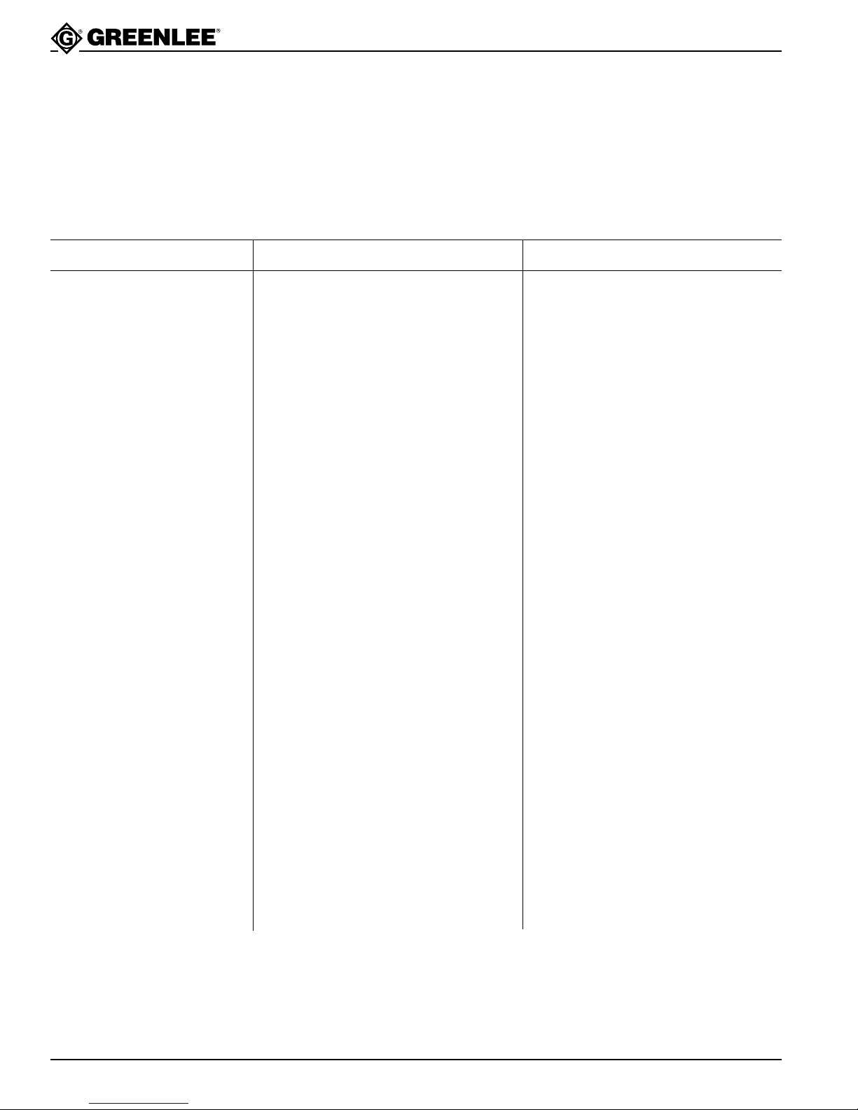
Minor Hydraulic Trouble Chart
The hydraulic unit should be observed constantly for
out-of-the-ordinary performance and unusual noises.
If any of these are present, shut off pump and take
corrective steps immediately to avoid possible expensive repairs later on. In most cases, a minor repair will
solve the problem but it is suggested that, if trouble
PROBLEM PROBABLE CAUSE POSSIBLE REMEDY
Lo-pressure failure Clogged-up screen Clean or replace #24.
Defective valve Replace #2.
Defective vanes or rotor Replace #16 & 17.
Oil supply low Add oil.
Hi-pressure failure Inoperative Lo-pressure stage See above.
Defective valve Replace #1.
continues, the unit should be returned to the factory
or to a qualified Service Station for the proper repair.
Under no conditions allow unqualified personnel to
attempt to repair the pump, particularly the pump block
unit, as serious, irreparable damage may result.
Sticking Plunger Replace #8 & 9.
Leaking ball check Ball seat 9/32 ball (26).
Sticking relief valve plunger Check #19 for proper movement.
Oil supply low Add oil.
Erratic pressure build-up Air in circuit, oil, supply low Add oil, run unit to work out air.
Dirt in system Flush out entire oil system and fill with
new oil (see page 5).
Necessary to add oil often Oil leaks Check for broken lines, loose fittings
or connections.
Pump motor will not start Not plugged into proper receptacle Check plug-in connection
Defective switch Replace #70.
Defective motor Send to factory or qualified service
center.
If the above corrective measures fail to make the pump function, it is recommended that you send the pump back to
the factory or to a qualified service center.
Greenlee Textron / Subsidiary of Textron Inc.
6
4455 Boeing Dr., Rockford, IL 61109-2988 815/397-7070
Page 7
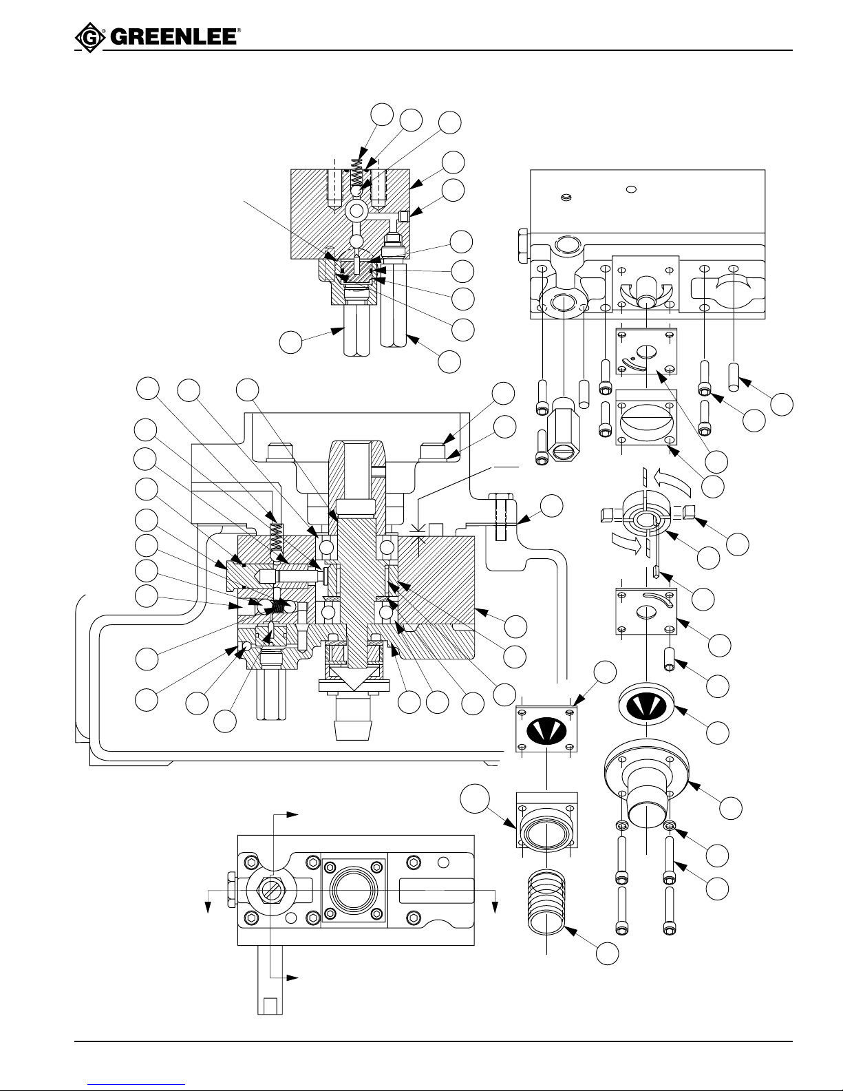
Exploded View
940m3 & 960m3 Series Hydraulic P o wer Pump
22
37
26
22
8
9
33
26
29
High Pressure
Unloading Check
Valve
31
4
25
SECTION B-B
19
40
2
20
41
Low Pressure
Relief Valve
13
1
66
40
61
0.096
0.106
R
O
T
A
T
I
O
N
39
14
11
71
7
16
17
36
23
38
28
12
20
15
6
24A
343
32
5
18
4
SECTION A-A
10A
B
24
10
30
35
A
A
27
B
Greenlee Textron / Subsidiary of Textron Inc.
7
4455 Boeing Dr., Rockford, IL 61109-2988 815/397-7070
Page 8
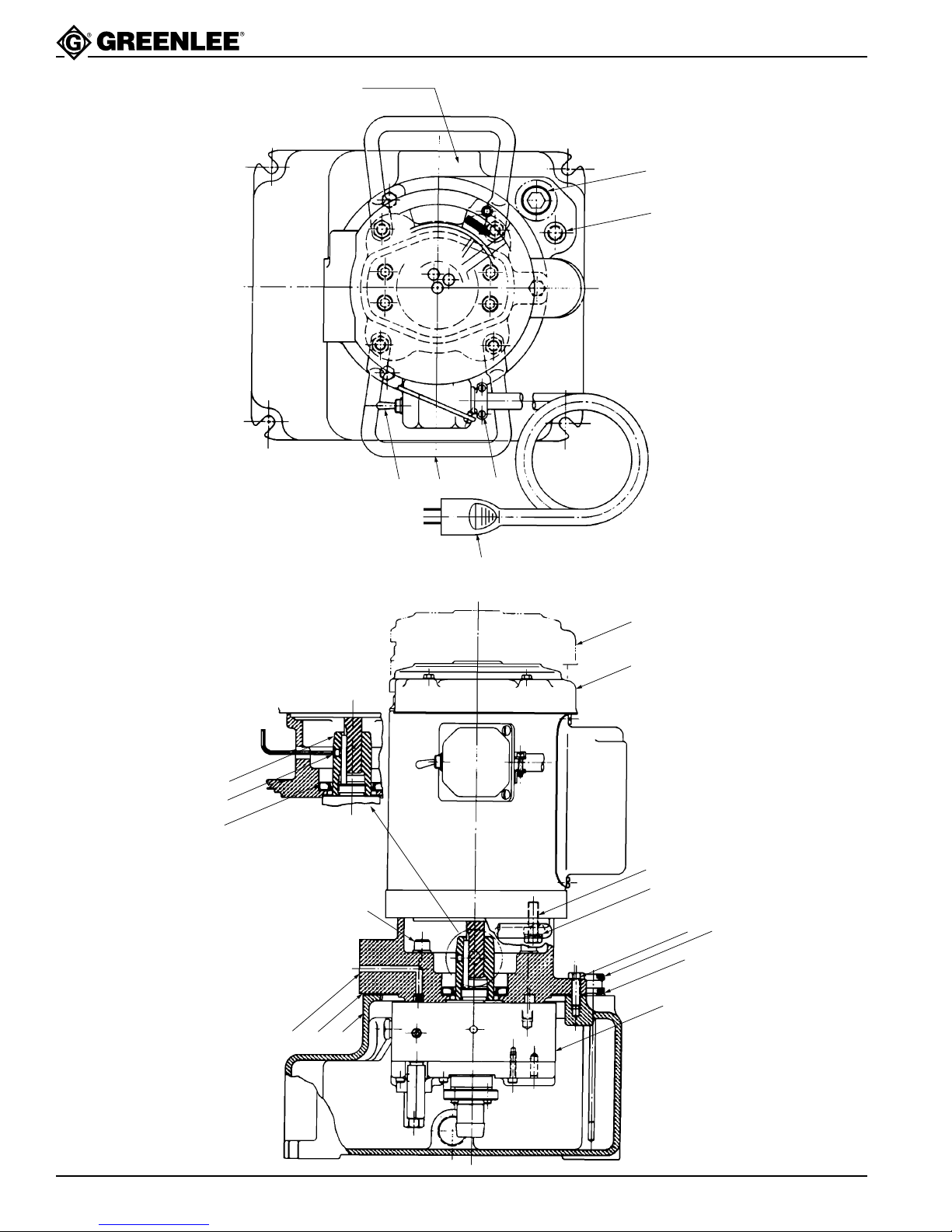
Exploded View
940m3 & 960m3 Series Hydraulic P o wer Pump
Serial No.
Location
B
Filler Plug
Dipstick-Vent
70 54 67
1/8 Allen
Wrench
57
65
59
NOTE: Remove set screw
before removing motor.
66
69
73
72
63
61
52
62
64
A
58 5355
Greenlee Textron / Subsidiary of Textron Inc.
8
4455 Boeing Dr., Rockford, IL 61109-2988 815/397-7070
Page 9

940m3 & 960m3 Series Hydraulic P o wer Pump
Parts List
No. 940-M3 Hydraulic Pump (# A, B and 50 - 72)
No. 960-M3 Hydraulic Pump (# A, B, 50 - 71 and 73)
Key Part No. Description Qty
A 501 8236.6 Block Unit, Pump (consists of #1 - 42) .....................................1
1 500 6067.8 Valve Unit, Relief ......................................................................1
2 501 7766.4 Valve Unit, Relief ......................................................................1
3 501 8194.7 Plate, Pump Mounting ..............................................................1
4 500 3493.6 Pin, Seal ...................................................................................1
5 501 8871.2 Spacer, Bearing........................................................................1
6 501 1855.2 Race, Outer ..............................................................................1
7 501 1862.5 Plug, Hi-Pressure Plunger ........................................................1
8 501 9060.1 Plunger, Hi-Pressure ................................................................1
9 501 9059.8 Bushing, Hi-Pressure Plunger ..................................................1
10 502 0424.6 Block, Intake .............................................................................1
10A 501 4859.1 Block, Intake .............................................................................1
11 501 4861.3 Plate, Pump ..............................................................................1
12 501 4862.1 Key, Lo-Pressure Pump............................................................1
13 501 4876.1 Shaft, Eccentric ........................................................................1
14 501 7130.5 Plate, Top..................................................................................1
15 501 7131.3 Plate, Bottom ............................................................................4
16 501 7135.6 Vane..........................................................................................1
17 501 7136.4 Rotor .........................................................................................1
18 501 7467.3 Dowel, Hollow ...........................................................................1
19 501 8195.5 Plunger, Check Valve ...............................................................1
20 501 8237.4 Block, Pump .............................................................................1
22 500 6111.9 Spring, Compression................................................................1
23 501 4865.6 Spring, Compression ................................................................1
24 502 1175.7 Screen, Intake ..........................................................................1
24A 501 6599.2 Screen, Intake ..........................................................................1
25 905 0014.8 O-Ring, 5/8 x 3/4 x 1/16 ...........................................................1
26 905 0436.4 Ball, 9/32 Grade #1 Chrome Steel ...........................................2
27 905 0490.9 Nipple, Intake (replaced by 10) ................................................1
28 905 0677.4 Ball, 5/32 Grade #1 Chrome Steel ...........................................1
29 905 0681.2 Ball, 3/8 Grade #1 Chrome Steel .............................................1
30 905 1526.9 Washer, #8 Hi-Collar Lock........................................................4
31 905 0824.6 Plug, 1/16 NPT Levi-Seal Socket Head Pipe ...........................1
32 905 0911.0 Roller, .125 x .750...................................................................30
33 905 1524.2 O-Ring, 1/2 x 5/8 x 1/16 ...........................................................1
34 905 0989.7 Bearing, Single Row Unshielded Ball.......................................1
35 905 0994.3 Screw, #8-32 NF x 1-1/4 Socket Head Cap .............................4
36 905 1111.5 Screw, 7/16-20 NF x 1/2 Cup Point Socket Set .......................1
37 905 2817.4 O-Ring, 7/16 x 9/16 x 1/16 .......................................................1
38 905 1241.3 Screw, #10-32 NF x 3/16 Flat Point Socket Set.......................1
39 905 1471.8 Screw, No. 10-32 NF x 7/8 Socket Head Cap..........................6
40 905 1472.6 Lok-Dowel, 1/4 x 3/4.................................................................2
41 905 1473.4 Bearing, Single Row Unshielded Ball.......................................1
52 501 5646.2 Dipstick Unit..............................................................................1
53 501 5695.0 Reservoir ..................................................................................1
54 501 2663.6 Handle ......................................................................................1
Greenlee Textron / Subsidiary of Textron Inc.
9
4455 Boeing Dr., Rockford, IL 61109-2988 815/397-7070
Page 10

Parts List (cont’d)
Key Part No. Description Qty
55 501 8292.7 Plate, Motor Mounting
57 501 8238.2 Adapter, Drive Shaft .................................................................1
58 501 5701.9 Gasket, Reservoir .....................................................................1
59 905 0320.1 Seal, 1-3/8 ID x 2-3/8 OD x 7/16 Thick Oil ...............................1
61 905 0506.9 Washer, 3/8 x .136 x .070 Lock ................................................8
62 905 0522.0 Screw, 5/16-18 NC x 1” Hex Head Cap ...................................3
63 905 0532.8 Screw, 3/8-16 NC x 1-1/4 Hex Head Cap ................................4
64 905 0387.2 O-Ring, 7/16 x 5/8 x 3/32 .........................................................1
65 905 1269.3 Screw, 1/4-20 NC x 1/4 Cup Point Head Set ...........................1
66 905 1474.2 Screw, 3/8-24 NF x 2/-1/2 Socket Head Cap ...........................4
67 918 5117.3 Connector .................................................................................1
69 918 5264.1 Cord ..........................................................................................1
70 918 5284.6 Switch .......................................................................................1
72 918 5183.1 Motor, 1 HP 1725 RPM (940-M3 Series only)..........................1
73 918 5466.0 Motor, 1-1/2 HP 3450 RPM (960-M3 Series only) ...................1
501 8416.4 Packing Repair Kit
Greenlee Textron / Subsidiary of Textron Inc.
4455 Boeing Drive, Rockford, IL 61109-2988 USA
Customer Center and Field Service: 800/435-0786
Fax (24 Hour) Customer Center: 800/451-2632 • 815/397-1865
Canada Fax (24 Hour) Customer Center: 800/524-2853
General Offices: 815/397-7070
Printed in the U.S.A.
 Loading...