

Page 1
INSTRUCTION MANUAL
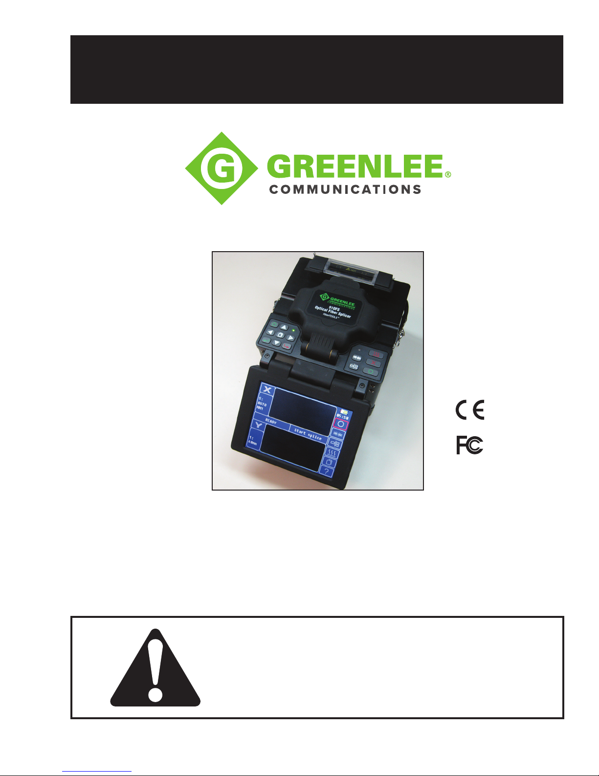
Optical Fiber Fusion Splicer
52063481 REV 5 © 2017 Greenlee Textron Inc. 10/17
910FS
Read and understand all of the instructions
and safety information in this manual
before operating or servicing this tool.
Register this product at www.greenlee.com
Page 2

Table of Contents
Preface 3
Important Safety Information 4
Section 1. Identification 9
Section 2. Operation 11
Setup ............................................................................................................................ 11
Splice Mode .................................................................................................................12
Fiber Preparation ..........................................................................................................13
Splicing Procedure .......................................................................................................15
Heating Protection Sleeve ............................................................................................17
Cooling Tray .................................................................................................................17
Splice-on Connectors ..................................................................................................17
Carrying Case with Work Table .................................................................................... 18
Upgrading Software .....................................................................................................19
Button Functions .......................................................................................................... 19
Appendixes ..................................................................................................................19
910FS Splicer
Section 3. Menu Operation 20
Splice Mode Menu (S–Mode) ....................................................................................... 22
Heater Mode Menu (H–Mode) ...................................................................................... 25
Maintenance ................................................................................................................. 27
Splice Set ..................................................................................................................... 30
Data Save ..................................................................................................................... 31
Set ................................................................................................................................ 33
Section 4. Specifications 38
Section 5. Troubleshooting 39
Appendix A. 910FS Fusion Splicer Cleaning 44
Appendix B. Practice Splicing 47
Appendix C. Greenlee Splice-on Connectors 49
Greenlee / A Textron Company 4455 Boeing Dr. • Rockford, IL 61109-2988 USA • 815-397-7070
2
Page 3

Preface
Description
910FS Splicer
The Greenlee Communications 910FS Optical Fiber Fusion Splicer is intended to fuse
bers, resulting in low splice loss and long-term stable splices. Splice loss depends on
certain conditions such as ber preparation, splicing parameters, and ber condition.
The 910FS fusion splicer uses a CDS (Core Detection System), which is also widely
known as PAS (Prole Alignment System). Two cameras sense the center of the core
of the bers, with the fusion splicer then adjusting in the X, Y, and Z dimensions to
automatically and precisely align the two ber cores. A fusing arc is applied, which then
provides the lowest loss fusion splice.
The 910FS with PAS technology is designed for splicing many types of optical bers.
It is small in size and lightweight, making it suitable for any operating environment. It is
easy to operate, and it splices fast while maintaining low splice loss.
Contents List
• 910FS fusion splicer
• 250 micron adapter pair
• 900 micron adapter pair
• SC/LC splice-on connector adapter
• Spare electrodes (one pair)
• AC adapter (power supply) with line cord
• Battery pack (installed in 910FS)
• Carry case
• 1.5 mm hex wrench
• Plastic tweezers
• Cooling tray
• Electrode polisher with 10 polishing strips
• Cleaning brush
• USB Cable
• RS-232 serial cable
Safety
Safety is essential in the use and maintenance of Greenlee tools and equipment.
Thisinstruction manual and any markings on the tool provide information for avoiding
hazards and unsafe practices related to the use of this tool. Observe all of the safety
information provided.
Purpose of This Manual
This instruction manual is intended to familiarize all personnel with the safe operation
and maintenance procedures for the Greenlee Communications 910FS Optical Fiber
Fusion Splicer.
Keep this manual available to all personnel. Replacement manuals are available upon
request at no charge at www.greenlee.com.
All specications are nominal and may change as design improvements occur. Greenlee Textron Inc. shall not
be liable for damages resulting from misapplication or misuse of its products.
berTOOLS is a trademark of Textron Innovations Inc.
Greenlee / A Textron Company 4455 Boeing Dr. • Rockford, IL 61109-2988 USA • 815-397-7070
3
Page 4
Important Safety Information
General
Use this unit for the manufacturer’s intended purpose only, as described in this manual.
Any other use can impair the protection provided by the unit. Do not use the splicer on
live bers.
Environmental Conditions
This tool is designed to operate at a maximum relative humidity of 95% and at altitudes
up to 5000 m (16,400 ft).
Before Applying Power
Verify that the tool is set to match the available line voltage and the correct fuse is
installed.
Do Not Operate in Explosive Atmosphere
Do not operate the tool in the presence of ammable gases or fumes.
Do Not Remove Instrument Cover
910FS Splicer
Do not remove the cover of the unit for any reason. It contains no user-serviceable parts.
SAFETY
ALERT
SYMBOL
This symbol is used to call your attention to hazards or unsafe practices which could
result in an injury or property damage. The signal word, dened below, indicates the
severity of the hazard. The message after the signal word provides information for
preventing or avoiding the hazard.
Immediate hazards which, if not avoided, WILL result in severe injury or death.
Hazards which, if not avoided, COULD result in severe injury or death.
Hazards or unsafe practices which, if not avoided, MAY result in injury or property
damage.
Greenlee / A Textron Company 4455 Boeing Dr. • Rockford, IL 61109-2988 USA • 815-397-7070
Read and understand all of the instructions and safety information in
this manual before operating or servicing this tool.
Failure to observe this warning could result in severe injury or death.
4
Page 5
Important Safety Information
Electric shock hazard:
Contact with live circuits could result in severe injury or death.
Wear eye protection when using this tool.
Fiber fragments can be extremely dangerous if they come into contacts with eyes or skin or are ingested.
Disconnect AC power cord from AC adapter inlet or wall socket (outlet) immediately if
user observes the following or if the splicer receives the following faults:
910FS Splicer
• Fumes, bad odor, noise, or overheat occurs.
• Liquid or foreign matter falls into cabinet.
• Splicer is damaged or dropped.
If these faults occur, return unit to Greenlee service center for repair. Leaving splicer in
a damaged state could cause equipment failure, electric shock or re, and could result
in severe injury or death.
Electric shock hazard:
• Use only AC adapter or battery charger designed for this splicer. Using an
improper AC power source could cause fuming, electric shock, or equipment
damage.
• Do not disassemble or modify splicer, AC adapter, or battery. Do not remove
or bypass any electrical or mechanical device (e.g., fuse or safety switch)
incorporated into design and manufacturing of this equipment.
• Never operate tool in an environment where ammable liquids or vapors exist.
Risk of re or explosion could result from the tool’s electrical arc in such an
environment.
• Do not use compressed gas or canned air to clean tool. They may contain
ammable materials that could ignite during electrical discharge.
• Do not touch electrodes when splicer is on and power is supplied to unit. The
electrodes generate high voltage and high temperatures that could cause a severe
shock or burn.
• Turn tool off and disconnect AC power cord before replacing electrodes.
Failure to observe these warnings could result in severe injury or death.
Greenlee / A Textron Company 4455 Boeing Dr. • Rockford, IL 61109-2988 USA • 815-397-7070
5
Page 6
910FS Splicer
Important Safety Information
Electric shock hazard: Use only proper power source.
• Check AC power source before use. Proper AC power source is 100–240 VAC,
50–60 Hz. Proper DC power source is 10–12 VDC. Improper AC or DC power
source could cause fuming, electric shock, or equipment damage.
• AC generators commonly produce abnormally high AC output voltage or irregular
frequencies. Measure output AC voltage with a circuit tester before connecting
the AC power cord. Such abnormally high voltage or frequency from a generator
could cause fuming, electric shock, or equipment damage. Make sure generator is
regularly checked and serviced.
Failure to observe these warnings could result in severe injury or death.
Electric shock hazard:
• Do not modify, abuse, heat, or excessively pull on power cord. Use of a damaged
cord could cause fuming, electric shock, or equipment damage.
• This tool uses a three-prong (core) AC power cord that contains an earthed
ground safety mechanism. This tool must be grounded. Use only the supplied
power cord. Never use a two-prong (core) power cord, extension cord, or plug.
• Connect AC power cord properly to splicer (inlet) and wall socket (outlet). When
inserting AC plug, make sure there is no dust or dirt on terminals. Engage by
pressing the female plug into the splicer (inlet) and the male plug into the wall
socket (outlet) until both plugs are fully seated. Incomplete engagement could
cause fuming, electric shock, or equipment damage.
• Do not short-circuit the terminals of AC adapter and optional battery. Excessive
electrical current could cause fuming, electric shock, or equipment damage.
• Do not touch the splicer, AC power cord, and AC plugs with wet hands.
• Do not operate splicer near hot objects, in hot temperature environments, in
dusty/humid atmospheres or when condensation is present on the tool. This may
result in electric shock, splicer malfunction, or poor splicing performance.
Failure to observe these warnings could result in severe injury or death.
Greenlee / A Textron Company 4455 Boeing Dr. • Rockford, IL 61109-2988 USA • 815-397-7070
6
Page 7
910FS Splicer
Important Safety Information
Explosion hazard: Follow these instructions when using lithium-ion battery:
• Do not charge battery with other methods than instructed.
• Do not dispose of battery in an incinerator or re.
• Do not charge or discharge battery near a ame or in direct sunlight.
• Do not excessively shake or jar battery.
• If battery leaks liquid residue, be careful handling battery so liquid does not
contact skin or eyes. If skin or eyes are contacted, immediately wash thoroughly
and seek medical attention. Dispose of battery and order replacement from
Greenlee.
• If charge did not complete in four hours or the “CHARGE” LED is constantly on,
stop charging immediately and call Greenlee service center for repair.
Failure to observe these warnings could result in severe injury or death.
Battery safety:
• Do not allow anything to contact the battery terminals.
• Do not immerse batteries in liquid. Liquid may create a short circuit and damage
the battery. If batteries are immersed, contact your service center for proper
handling.
• Do not place the battery into a pocket, tool pouch, or tool box with conductive
objects. Conductive objects may create a short circuit and damage the battery.
• Do not place a battery on moist ground or grass. Moisture may create a short
circuit and damage the battery.
• Do not store the battery at more than 122 °F (50 °C) or less than –4 °F (–20 °C).
Damage to the battery can result.
• Do not use another manufacturer’s charger. Other manufacturers’ chargers may
overcharge and damage the battery.
• Do not attempt to open the battery. It contains no user-serviceable parts.
Failure to observe these precautions may result in injury and may damage the unit.
Greenlee / A Textron Company 4455 Boeing Dr. • Rockford, IL 61109-2988 USA • 815-397-7070
7
Page 8
Important Safety Information
• Do not store tool in areas of extremely high temperature and humidity.
• Do not touch protection sleeve or tube heater during or immediately after heating.
These surfaces are very hot and touching them may result in burns.
• Do not place tool in an unstable or unbalanced position. Tool may shift or lose
balance, causing unit to fall.
• This tool is precision adjusted and aligned. Do not allow unit to receive a strong
shock or impact. Use supplied carrying case for transportation and storage.
Carrying case protects tool from damage, moisture, vibration, and shock.
Failure to observe these precautions may result in injury and may damage the unit.
910FS Splicer
Follow these instructions for handling electrodes:
• Use only specied electrodes.
• Set new electrodes in correct position.
• Replace electrodes as a pair.
Failure to observe this precaution may cause abnormal arc discharge, which may
result in equipment damage or degradation in splicing performance.
• Do not use any chemical other than pure alcohol (99% or greater) to clean the
objective lens, V-groove, mirror, LCD monitor, etc. Use of other chemicals may
cause blurring, discoloration, damage, or deterioration.
• This tool requires no lubrication. Oil or grease may degrade the splicing
performance and damage the splicer.
• This equipment must be repaired or adjusted by a qualied technician or engineer.
Incorrect repair may cause re or electric shock. Contact Greenlee service center
for repair.
Failure to observe these precautions may result in injury and may damage the unit.
Greenlee / A Textron Company 4455 Boeing Dr. • Rockford, IL 61109-2988 USA • 815-397-7070
8
Page 9
Section 1. Identification
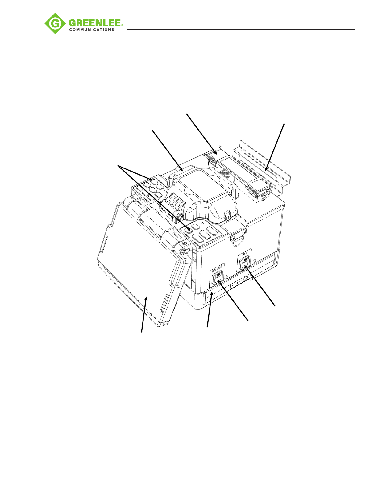
Components of Splicer
Tube Heater
Wind Protector
Keypads
910FS Splicer
Cooling Tray
Greenlee / A Textron Company 4455 Boeing Dr. • Rockford, IL 61109-2988 USA • 815-397-7070
LCD
Battery
Compartment
9
USB
Port
RS-232
Port
Page 10
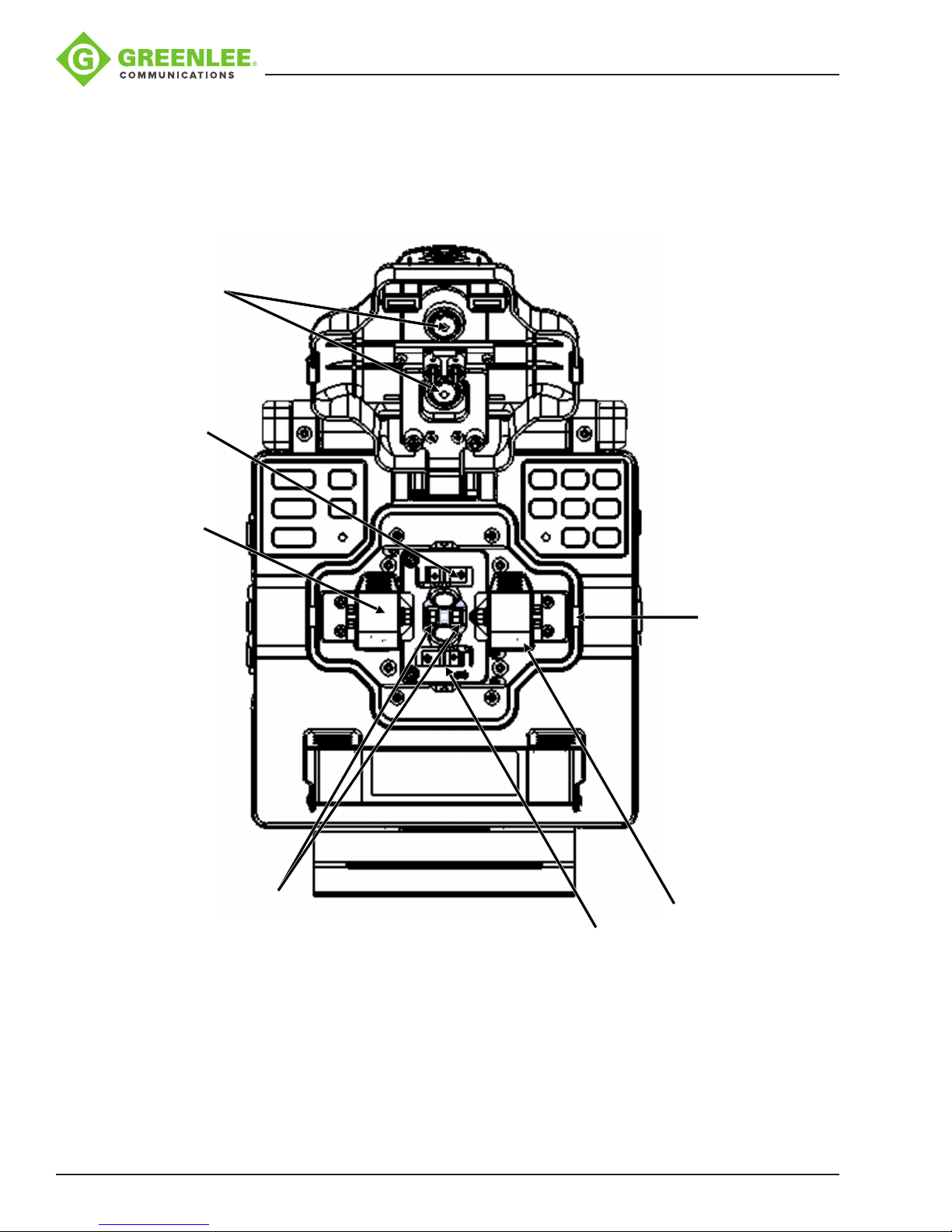
Top View
Wind Protector
Electrode Cover
910FS Splicer
Mirror
Fiber Adapter
V-groove
Electrode
Cover
Guide Groove
Fiber
Adapter
Greenlee / A Textron Company 4455 Boeing Dr. • Rockford, IL 61109-2988 USA • 815-397-7070
10
Page 11
Section 2. Operation
Setup
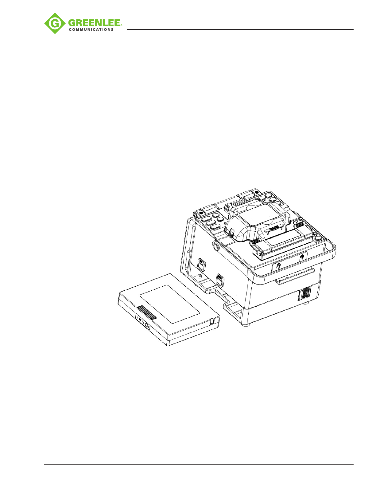
Installing Battery in Splicer
The 910FS can be powered by an external power adapter and battery.
Inserting the Battery
Remove the protective cover from the battery contacts. Insert the battery into the battery
compartment until it clicks into place.
Removing the Battery
Turn off the splicer. Push the release button, located on the side of the splicer body, and
remove the battery.
910FS Splicer
Two Methods of Checking Remaining Battery Capacity
• If the battery is already installed in the splicer, turn the splicer ON. The battery is
automatically identied, and the remaining battery capacity is displayed on the
“Ready” screen.
• Press the battery check button on the battery pack. The remaining battery capacity
is indicated on the LED indicator.
Greenlee / A Textron Company 4455 Boeing Dr. • Rockford, IL 61109-2988 USA • 815-397-7070
11
Page 12
910FS Splicer
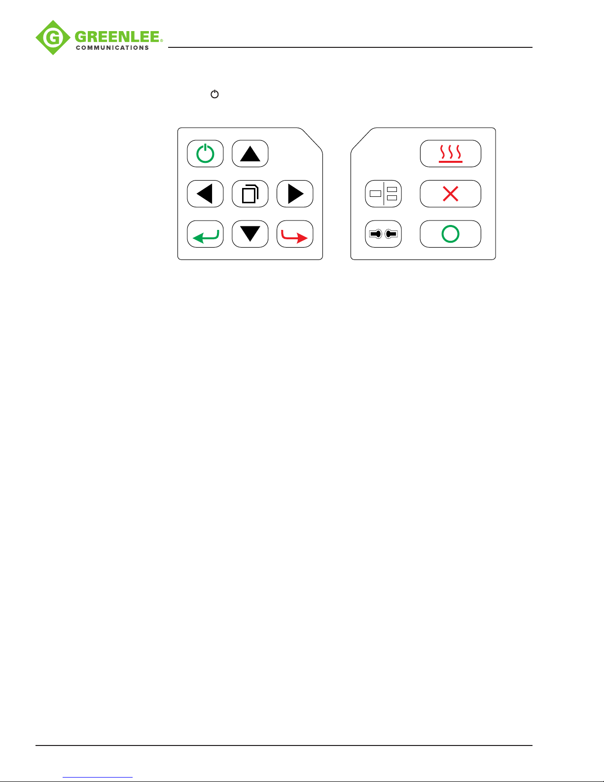
Turning Splicer ON
Press and hold until the LED on the keypad turns ON (green color).
?
The “Ready” screen is displayed after all the motors reset to their initial positions.
The power source type is automatically identied. If the battery is used, the remaining
battery capacity is displayed.
Splice Mode
Use SM splice mode for standard SM ber (ITU-TG.652) splicing. It performs splices in
9seconds and is the quickest mode for SM ber splicing.
Use AUTO splice mode if ber type is not identied. Splice takes 2 seconds longer but it
covers most conventional ber splicing for the following reasons:
• AUTO mode rst identies ber type by analyzing ber prole, and the splicing
condition is chosen for the type of ber. The types of bers covered by AUTO are
all the conventional bers, such as SMF (G652), BIF (G657), NZDSF (G655), MMF
(G651), etc. AUTO mode takes longer than the SM processes but is recommended
in cases where the ber type is not positively identied or if the user is new to fusion
splicing.
• AUTO mode uses an automatic arc calibration function, which monitors the splicing
process and ensures adequate arc power for the splice.
Automatic Arc Calibration Function
When the automatic ARC calibration function is enabled the previous splice’s ARC
power is used. If the ambient conditions or type of ber has changed an ARC calibration
may be required. The automatic arc calibration function works in AUTO modes only. It
is not active in the standard splice modes. When using those modes, performing arc
calibration before splicing is strongly recommended.
Greenlee / A Textron Company 4455 Boeing Dr. • Rockford, IL 61109-2988 USA • 815-397-7070
12
Page 13
Fiber Preparation
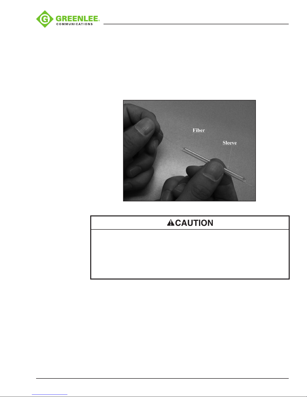
Placing Protection Sleeve over Fiber
Place the protection sleeve over the ber. Clean optical ber with alcohol-soaked gauze
or lint-free tissue approximately 100 mm (4 in) from the tip.
Note: Splice-on connectors are pre-cleaved. Do not attempt to clean the ber on the
splice-on connector. Follow the instructions supplied with the splice-on connectors.
910FS Splicer
• Clean optical ber with alcohol-soaked gauze or lint-free tissue. Dust particulates
can enter the protection sleeve, resulting in a ber break or attenuation increase.
• Make sure ber is passed through the protection sleeve.
• When protection sleeve core tube is longer than the length of outer sheath, cut off
excess sleeve to avoid micro bend after heating.
Failure to observe these precautions may result in injury and may damage the unit.
Greenlee / A Textron Company 4455 Boeing Dr. • Rockford, IL 61109-2988 USA • 815-397-7070
13
Page 14
910FS Splicer
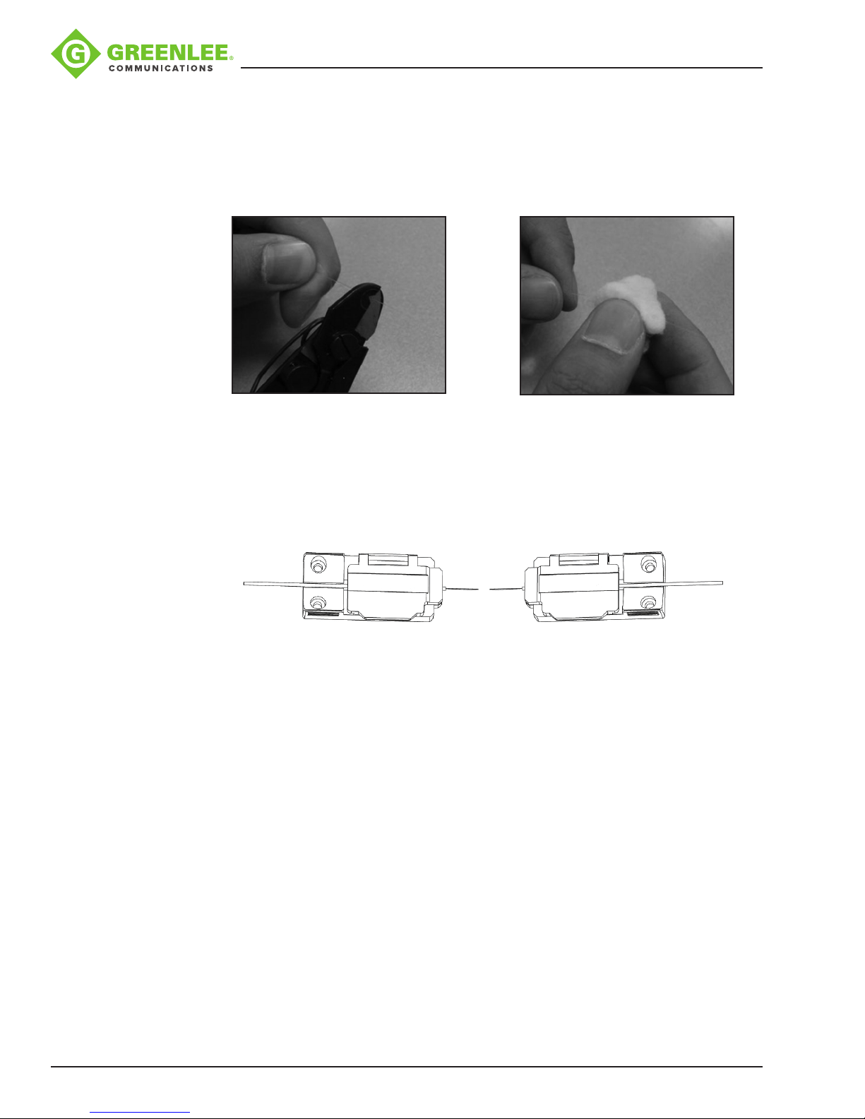
Stripping and Cleaning Fiber
Use the supplied ber stripping tool to strip the outer coating 30 to 40 mm (1.25 to 1.5
in) from its tip. Thoroughly clean the ber with alcohol-soaked (99% or greater) gauze or
lint-free tissue.
Fiber Cleaving
Do not let the ber end-face touch anything. Place the ber into the universal adapter,
and insert the adapter into the 910CL. Follow the instructions for the 910CL to cleave
the ber.
Loading Fiber into Splicer
1. Open the wind protector and install the ber adapters into the splicer, making sure
the ber is positioned into the center of the V-grooves.
2. Close the wind protector.
Greenlee / A Textron Company 4455 Boeing Dr. • Rockford, IL 61109-2988 USA • 815-397-7070
14
Page 15
Splicing Procedure
To ensure a good splice, the optical ber is observed with the image processing system
equipped in the 910FS. However, in some cases the image processing system cannot
detect a faulty splice. Visual inspection with the monitor is often necessary for better
splicing yield. Observe the following standard operating procedure:
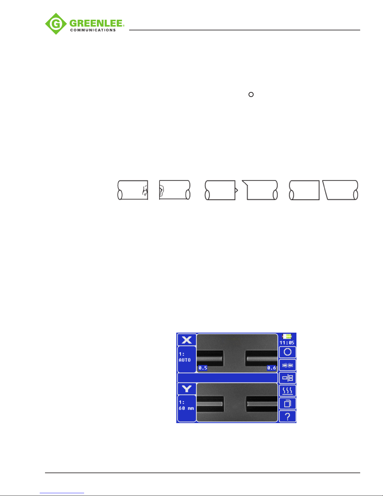
• After bers are loaded into the splicer, press and the bers will move toward each
other. The ber motion stops and the cleaning arc is performed. The cleave angle
and end-face quality are checked. If the measured cleave angle is greater than its
set threshold or ber chipping is detected, the beeper sounds and an error message
warns the operator. The splicing procedure pauses. If no error message is displayed,
the below stated end-face conditions are used for visual inspection. If observed,
remove the ber from the splicer and repeat ber preparation. These ber cleave
defects may cause a faulty splice.
910FS Splicer
Chip Lip Incline
• After ber inspection, the bers are aligned core-to-core or cladding-to-cladding.
Cladding axis offset and core axis offset measurements can be displayed.
• After completion of ber alignment, an arc discharge is performed to splice the
bers.
• Estimated splice loss is displayed upon completion of splicing. Splice loss is
affected by factors stated in Section 5. These factors are taken into account
to calculate, or estimate, splice loss. The calculation is based on dimensional
parameters, such as MFD, cleave quality, and fusion splice shape after the splice.
If either the cleave angle measured or the estimated splice loss exceeds its
set threshold, an error message is displayed. If the spliced ber is detected as
abnormal, such as “Fat”, “Thin” or “Bubble”, an error message is displayed. If no
error message is displayed but the splice looks poor by visual inspection through the
monitor, it is strongly recommended to resplice.
Greenlee / A Textron Company 4455 Boeing Dr. • Rockford, IL 61109-2988 USA • 815-397-7070
15
Page 16
910FS Splicer
Notes:
• Splice point sometimes looks a bit fatter than other parts. This is considered a
normal splice and does not affect splice loss.
• To change threshold for estimated splice loss or cleave angle, refer to “Splice
Mode” in this manual for details.
• Splice loss may be improved in some cases by additional arc discharges.
Press for an additional arc discharge (re-arc). Splice loss estimate and
splice check are performed again. Splice loss may be worsened in some cases
by additional arc discharges (re-arcs). Additional arc discharge can be set to
“disabled”, or limited to the number of additional arcs.
• Splicing result is automatically saved in splicer memory.
Arc Calibration
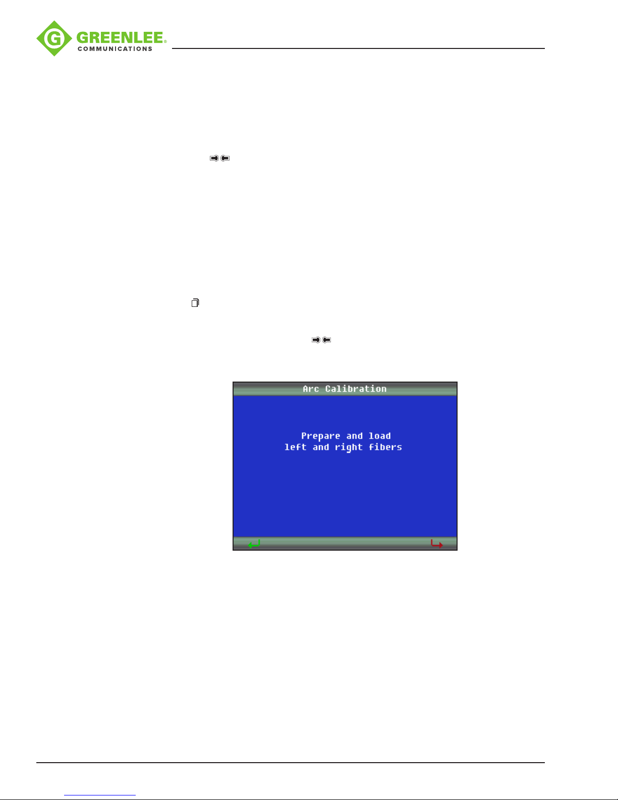
When a splicing session is rst started or if the splicing environment has changed, it is
recommended that the technician perform an arc calibration.
1. Place cleaved bers into the splicer.
2. Press and navigate to the “Maintenance” menu. Select “Arc Calibration.”
3. Follow the on-screen prompts.
Note: It might be necessary to push up to three times until “the arc adjust OK”
prompt is achieved.
Greenlee / A Textron Company 4455 Boeing Dr. • Rockford, IL 61109-2988 USA • 815-397-7070
16
Page 17
Heating Protection Sleeve
1. Transfer the ber with protection sleeve from the centering device to the tube heater.
2. Close the tube heater lid.
Notes:
• Make sure the splice point is located at the center of the protection sleeve.
• Make sure the strength member in the protection sleeve is placed downward.
• Make sure the ber is not distorted.
• The splice-on connector must be installed on the right-hand side of the splicer
heater. Use heater prole #1 for the SOC.
3. Press to start tube heating. The beeper sounds and the HEAT LED (red color)
turns off when tube heating is completed.
4. Open the tube heater lids and remove the protected ber from the tube heater. Apply
some tension to the ber while removing it from the tube heater.
5. Visually inspect the nished sleeve to verify that no bubbles or debris/dust is present
in the sleeve.
910FS Splicer
Cooling Tray
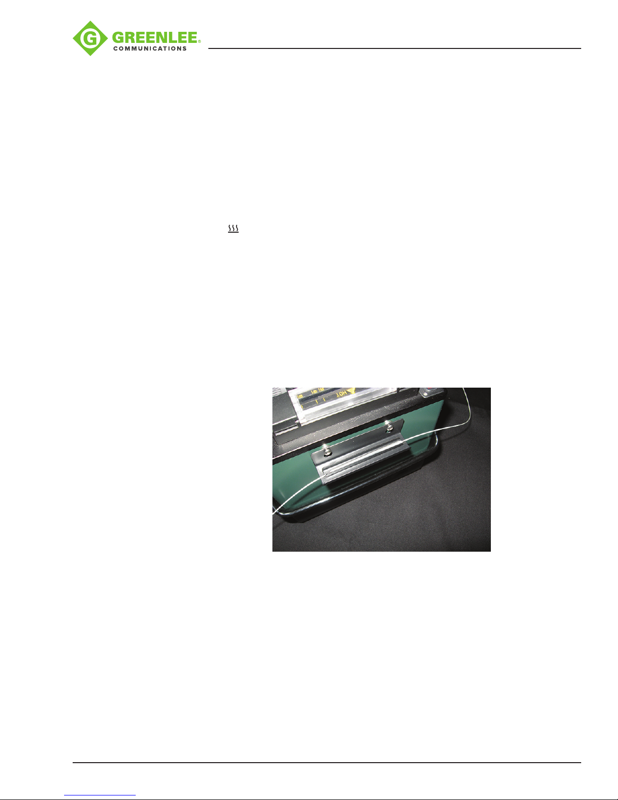
Place the splice into the cooling tray on the back of the 910FS splicer.
Splice-on Connectors
The 910FS uses the Greenlee version of splice-on connectors. The 910FS currently
supports SC, LC, FC, and ST versions (both PC and APC nish, where applicable).
Follow the instructions supplied with the SOC packaging.
Greenlee / A Textron Company 4455 Boeing Dr. • Rockford, IL 61109-2988 USA • 815-397-7070
17
Page 18
Carrying Case with Work Table
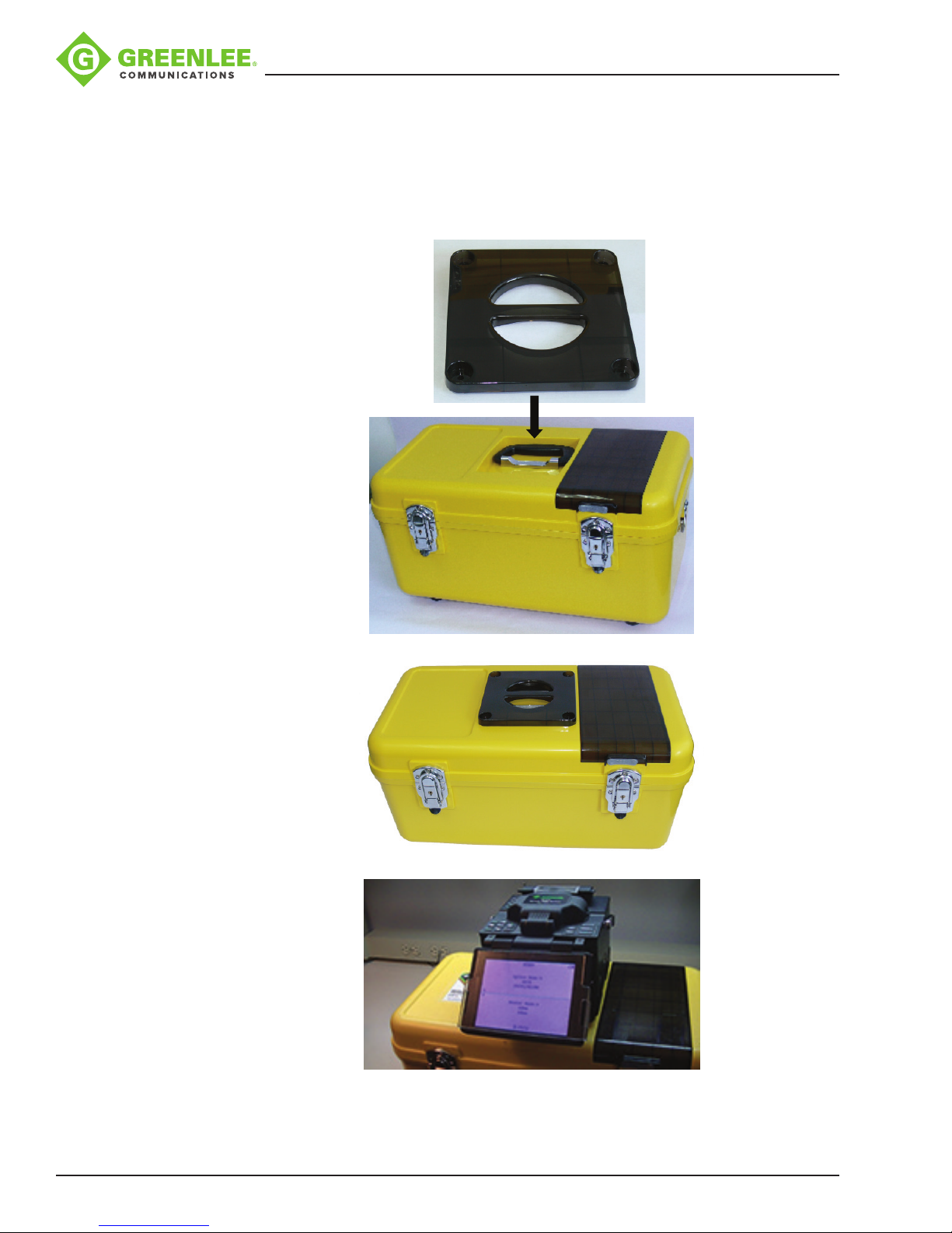
The top cover of the carrying case can be used as a work table. Place the tray mounting
attachment on the top of the case and mount the fusion splicer on top of the mounting
attachment, as shown below. This provides a safe and secure work surface.
910FS Splicer
Greenlee / A Textron Company 4455 Boeing Dr. • Rockford, IL 61109-2988 USA • 815-397-7070
18
Page 19
Upgrading Software
The 910FS software can be upgraded using the online software upgrade tool
at www.greenlee.com.
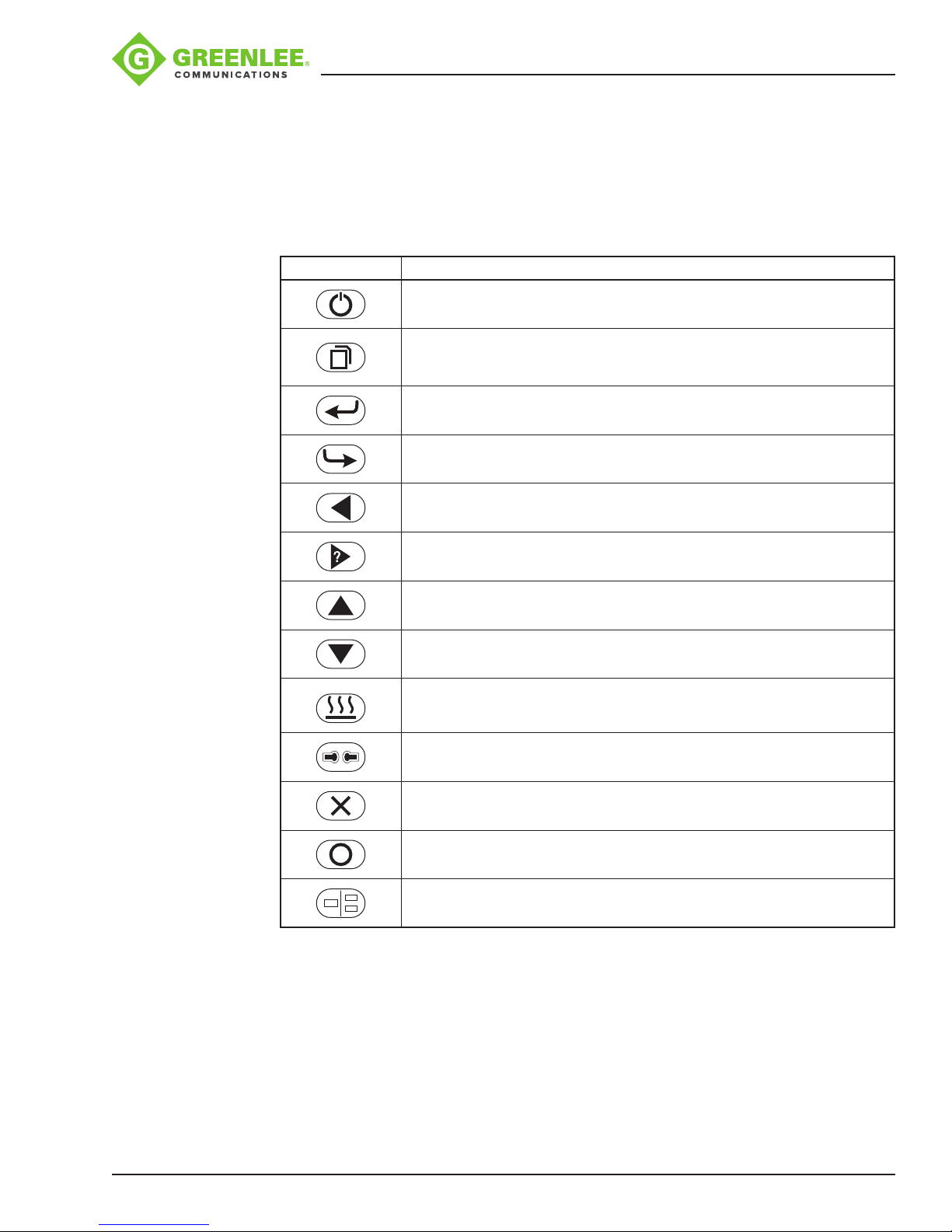
Button Functions
Button Description
910FS Splicer
Turns the splicer ON/OFF
Menu key
Enter key
Return/Exit key
Left key
Appendixes
Right key/Help key
Up key/Bright key for LCD
Down key/Dark key for LCD
Start/Stop heating protection
Re-calibrates arc power
Resets the motor position
Starts splicing work
Switches between X, Y and X/Y views
Refer to the following appendixes at the end of this manual for additional operating
information:
• Appendix A—910FS Fusion Splicer Cleaning
• Appendix B—Practice Splicing
• Appendix C—Greenlee Splice-on Connectors
Greenlee / A Textron Company 4455 Boeing Dr. • Rockford, IL 61109-2988 USA • 815-397-7070
19
Page 20
Section 3. Menu Operation
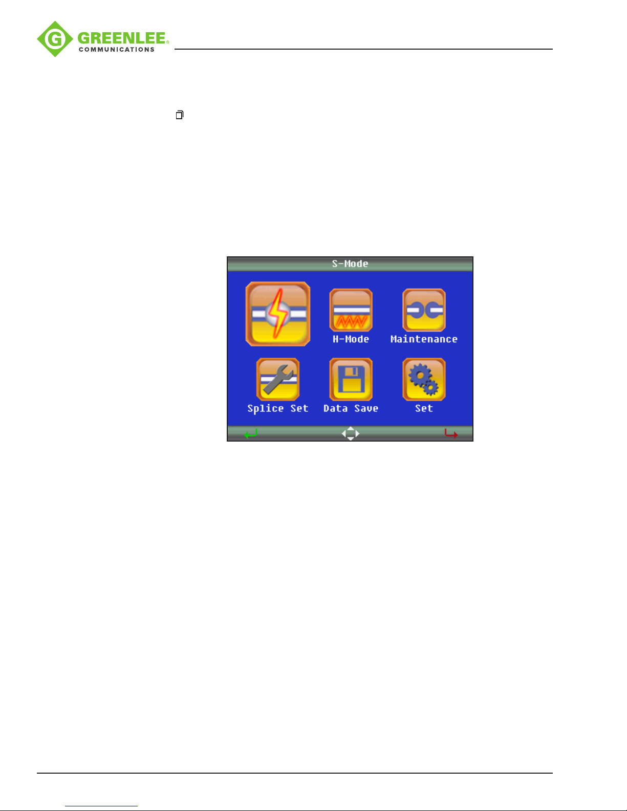
Press to enter the splicer menu. There are six main menus:
1. Splice Mode Menu (S–Mode)
2. Heater Mode Menu (H–Mode)
3. Maintenance
4. Splice Set
5. Data Save
6. Set
910FS Splicer
Greenlee / A Textron Company 4455 Boeing Dr. • Rockford, IL 61109-2988 USA • 815-397-7070
20
Page 21

Explanation of Splice Modes
Mode No. Splice Mode Description
For splicing in most cases; the splicer will automatically adjust splice parameters
1 AUTO
2 AUTO SM
3 AUTO DS
4 AUTO NZ
5 AUTO MM1
6 SM
7 DS
8 NZ
9 MM1
10 AT1(SM)
11 SM FAST
12~60
BLANK
(other modes)
according to ber type.
Automatic arc calibration works in this splice mode.
For splicing standard single-mode ber (ITU-T G652).
The MFD is 9 to 10 µm at wavelength of 1310 nm.
Automatic arc calibration works in this splice mode.
For splicing dispersion-shifted ber (ITU-T G653).
The MFD is 7 to 9 µm at wavelength of 1550 nm.
Automatic arc calibration works in this splice mode.
For splicing non-zero dispersion-shifted ber (ITU-T G655).
The MFD is 9 to 10 µm at wavelength of 1550 nm.
Automatic arc calibration works in this splice mode.
For splicing multi-mode ber (ITU-T G651). Core diameter: 50.0 to 62.5 µm.
Automatic arc calibration works in this splice mode.
For splicing standard single-mode ber (ITU-T G652).
The MFD is 9 to 10 µm at wavelength of 1310 nm.
User can edit all parameters of this splice mode such as prefuse power, prefuse
time, arc power, arc time, align, proof test, etc.
The manual splicing operation is provided. Automatic arc calibration does not work
in this splice mode.
For splicing dispersion-shifted ber (ITU-T G653).
The MFD is 7 to 9 µm at wavelength near 1550 nm.
User can edit all parameters of this splice mode such as prefuse power, prefuse
time, arc power, arc time, align, proof test, etc.
The manual splicing operation is provided. Automatic arc calibration does not work
in this splice mode.
For splicing non-zero dispersion-shifted ber (ITU-T G655).
The MFD is 9 to 10µm at wavelength of 1550 nm.
User can edit all parameters of this splice mode such as prefuse power, prefuse
time, arc power, arc time, align, proof test, etc.
The manual splicing operation is provided. Automatic arc calibration does not work
in this splice mode.
For splicing multi-mode ber (ITU-T G651). Core diameter: 50.0 to 62.5 µm.
User can edit all parameters of this splice mode such as prefuse power, prefuse
time, arc power, arc time, align, proof test, etc.
The manual splicing operation is provided. Automatic arc calibration does not work
in this mode.
User can set the attenuation value in the range of 0.1 to 15 dB.
Set the desired splice loss. If after the splice is completed the desired loss is not
achieved, the user can adjust the splicing coefcient. Increasing the coefcient will
increase the desired loss; decreasing the coefcient will reduce the splice loss.
For splicing standard single-mode ber (ITU-T G652).
The MFD is 9 to 10 µm at wavelength of 1310 nm.
It is the fastest splice mode at 9 seconds splicing time. This mode process does
not analyze ber geometry.
User can assign these as their own custom splicing proles.
910FS Splicer
Greenlee / A Textron Company 4455 Boeing Dr. • Rockford, IL 61109-2988 USA • 815-397-7070
21
Page 22
Splice Mode Menu (S–Mode)
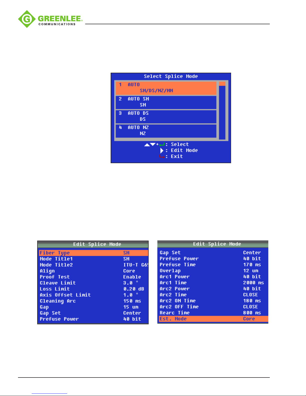
(1) Select Splice Mode
Select “S–Mode” to access the available splicing modes. Use p and q to highlight the
desired splicing mode. Then press 8 to conrm.
910FS Splicer
Select an appropriate splice mode for the type of ber to be spliced, and press porq
to select the splice mode. Then press 8 to conrm.
Note: “1 AUTO SM/NZ/DS/MM” mode is recommended for splicing in most cases. In
this mode, the splicer automatically adjusts splice parameters according to the ber
type.
(2) Edit Splice Mode
Splicing parameters in each splice mode can be modied.
In “Select Splice Mode” menu, press u to enter “Edit Splice Mode” and modify the
splice mode as shown below.
Press porq to select the parameter to be modied, and then press 8 to enter the
parameter setting.
Press porq to modify the parameter, and then press 8 to conrm.
Greenlee / A Textron Company 4455 Boeing Dr. • Rockford, IL 61109-2988 USA • 815-397-7070
22
Page 23

910FS Splicer
Note: In AUTO mode, certain parameters cannot be changed.
Parameter Description
Arc Power In SM/DS/MM/NZ/AUTO modes the arc power is xed at 40 bits.
Arc Time Arc time is xed at 1500 ms for SM and DS modes, 2000 ms for
NZ mode, and 3000 ms for MM mode. This is automatically set
depending on the ber type when AUTO mode is selected.
Edit Mode for Splicing
• Fiber Type: Select or enter the name of ber being spliced.
• Mode Title1: Enter type of ber.
• Mode Title2: Enter alternate name of ber type.
• Align: Select Core, Clad or Manual options. In manual mode the user can control the
motors by hand.
• Proof Test: Enable or disable the tension test after splicing. Disable this for splice-on
connector use.
• Cleave Limit: Set or disable the cleave error limit in degrees.
• Loss Limit: Set or disable the splice loss notication level.
• Axis Offset Limit: Set or disable the axis offset error limit in degrees.
• Cleaning Arc: Set or disable the duration of the cleaning arc.
• Gap: Increase the gap if the bers are “soft” and melt too easily. Decrease the gap if
the bers are “hard to melt”.
• Gap Set: Set the gap closer to the larger diameter core ber when splicing
dissimilar-sized bers. This may also be necessary when splicing what the user
may consider to be the same size ber but the two bers are from different
manufacturers.
• Prefuse Power: Set or disable the power to the electrode during the initial fusing
cycle.
• Prefuse Time: Set or disable the duration of the prefuse cycle.
• Overlap: Set or disable the overlap closer if the bers are hard to splice or the core
diameter is thick. (The harder the closer, the thicker the closer; the softer the farther,
the thinner the farther.)
• Arc1 Power: Increase or decrease or disable the Arc1 power.
• Arc1 Time: Increase or decrease or disable the Arc1 duration.
• Arc2 Power: Increase or decrease or disable the Arc2 power.
• Arc2 Time: Increase or decrease or disable the Arc2 duration.
• Arc2 ON Time: Set or disable the Arc2’s working (arcing) duration.
• Arc2 OFF Time: Set or disable the Arc2’s off duration.
• Rearc Time: Set or disable the duration of the Rearc.
Greenlee / A Textron Company 4455 Boeing Dr. • Rockford, IL 61109-2988 USA • 815-397-7070
23
Page 24
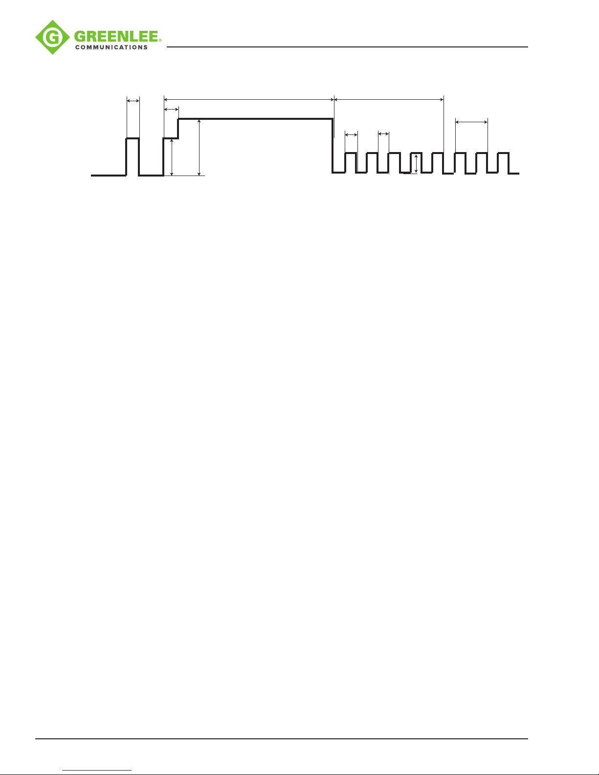
Summary of electrode activation:
C D
A
B
G
F
A: Cleaning Arc
B: Prefuse Time
C: Arc1 Time
D: Arc2 Time
E: Rearc Time
F: Prefuse Power
G: Arc1 Power
910FS Splicer
E
I J
H
H: Arc2 Power
I: Arc2 ON Time
J: Arc2 OFF Time
Note: Not all settings are available in the AUTO modes.
This is a general guideline for the user to control the fusion settings. Every type of ber
has its own characteristics and properties that may require the manual setting of these
parameters. The user will have to perform careful experiments with their individual bers
to obtain optimum results.
Greenlee / A Textron Company 4455 Boeing Dr. • Rockford, IL 61109-2988 USA • 815-397-7070
24
Page 25
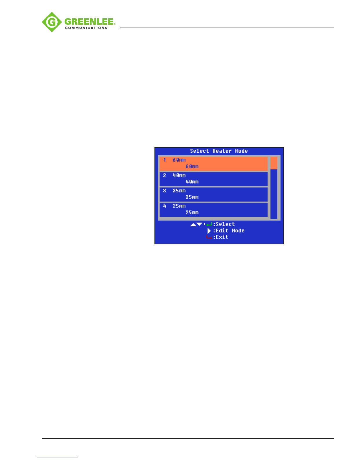
Heater Mode Menu (H–Mode)
There are 20 user-programmable heating modes. Select the one most suitable for the
protection sleeve used.
Each tube-heating mode is optimized for a type of protection sleeve. These modes can
be found in the database area for reference. Copy the appropriate one and paste it into
the user-programmable area. The operator can edit the user-programmable modes.
(1) Select Heater Mode
Select “H–Mode” to access the available heater modes. Use p and q to highlight the
desired heater mode. Then press 8 to conrm.
Select the heater mode most suitable for the protection sleeve to be used.
910FS Splicer
Press p or q to select a heater mode. Then press 8 to conrm.
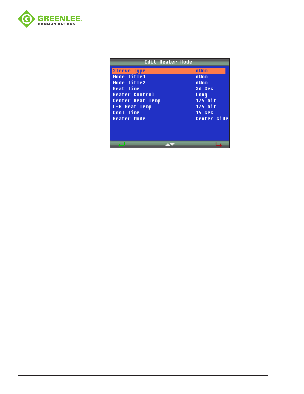
(2) Edit Heater Mode
Tube-heating conditions stored in heater mode can be edited or changed.
Editable parameters include Heat Time and Heat Temp (heating temperature). Heat
Time will automatically adjust according to atmospheric conditions, e.g., ambient
temperature. The real Heat Time may vary from set Heat Time.
Sets Heating Temperature: Fiber coating may melt if Heat Temp is over 190 °C (374 °F).
Sets Finish Temp (Finish Temperature): When heater approaches this temperature, the
buzzer beeps, announcing the sleeve is cooled down and is ready to be removed from
the heater.
Greenlee / A Textron Company 4455 Boeing Dr. • Rockford, IL 61109-2988 USA • 815-397-7070
25
Page 26
910FS Splicer
In “Select Heater Mode”, press u to enter the “Edit Heater Mode” menu as shown
below.
Press porq to select the parameter to be modied, and then press 8 to enter the
parameter setting.
Press porq to modify the parameter, and then press 8 to conrm.
Edit Mode for Heater Settings
• Sleeve Type: Enter the protection sleeve name.
• Mode Title1: Enter the heater mode setting name.
• Mode Title2: Enter the alternate heater mode setting name.
• Heat Time: Enter the heater duration.
• Heater Control: Enter the splice protector size as Long, Mid or Micro.
• Center Heat Temp: Enter the center of the oven temperature.
• L-R Heat Temp: Enter the left- and right-hand sides oven temperature.
• Cool Time: Disable it when not needed. Also, to disable the beep. (The “beep” is
activated when the “cool time” has been set as “x” seconds; there is no “beep”
when the cool time has been set to zero seconds.)
• Heater Mode: Enter the mode as center and sides activated or center only
activated.
Greenlee / A Textron Company 4455 Boeing Dr. • Rockford, IL 61109-2988 USA • 815-397-7070
26
Page 27
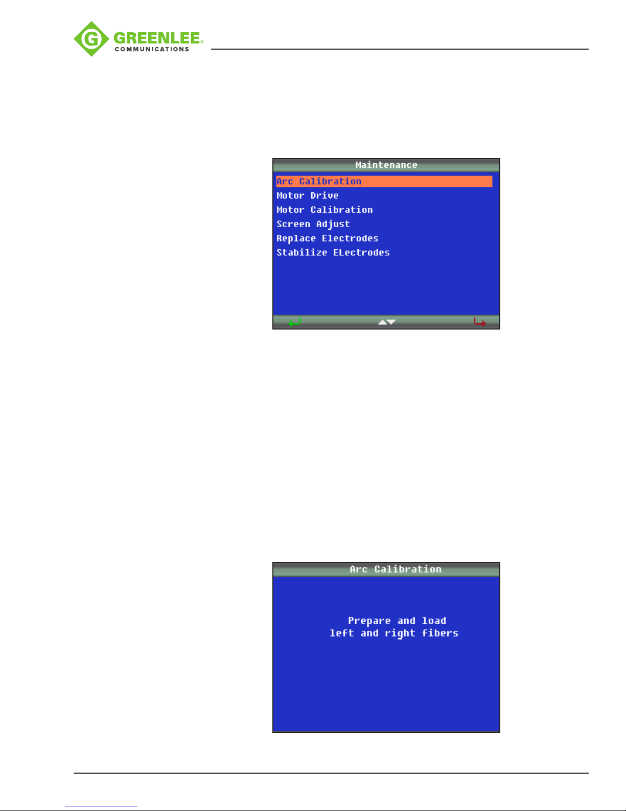
Maintenance
910FS Splicer
The 910FS can perform routine maintenance. In “Maintenance”, the operator can
calibrate arc, set motor drive, calibrate motors, adjust screen, replace electrodes, and
stabilize electrodes.
Arc Calibration
Used to calibrate arc function to obtain the best splicing results when a splicing session
is rst started or if the splicing environment has changed.
1. Place splicer in Splice Mode #1 (AUTO).
2. Select “Arc Calibration.”
3. Prepare and load bers.
4. Press 8 .
5. If too low or high, load new bers.
6. Press 8 .
7. Repeat steps 1–4 until “arc adjust OK” displays on splicer screen.
Greenlee / A Textron Company 4455 Boeing Dr. • Rockford, IL 61109-2988 USA • 815-397-7070
27
Page 28
910FS Splicer
Cleaning the Electrodes
It may be necessary to clean the electrodes if the arc calibration fails or if the 910FS is
not splicing properly.
1. Remove the electrodes and clean the electrodes using the electrode polisher.
2. Insert the electrode tip into the hole of the electrode polisher and gently rotate the
electrode.
3. Wipe the electrodes with 99% pure IPA. Do not touch the electrode surface with
your ngers. Now is a good time to clean the objective lens while the electrodes are
not in the way.
4. Re-install the electrodes into the splicer.
5. Perform an arc calibration to calibrate the power to the electrodes.
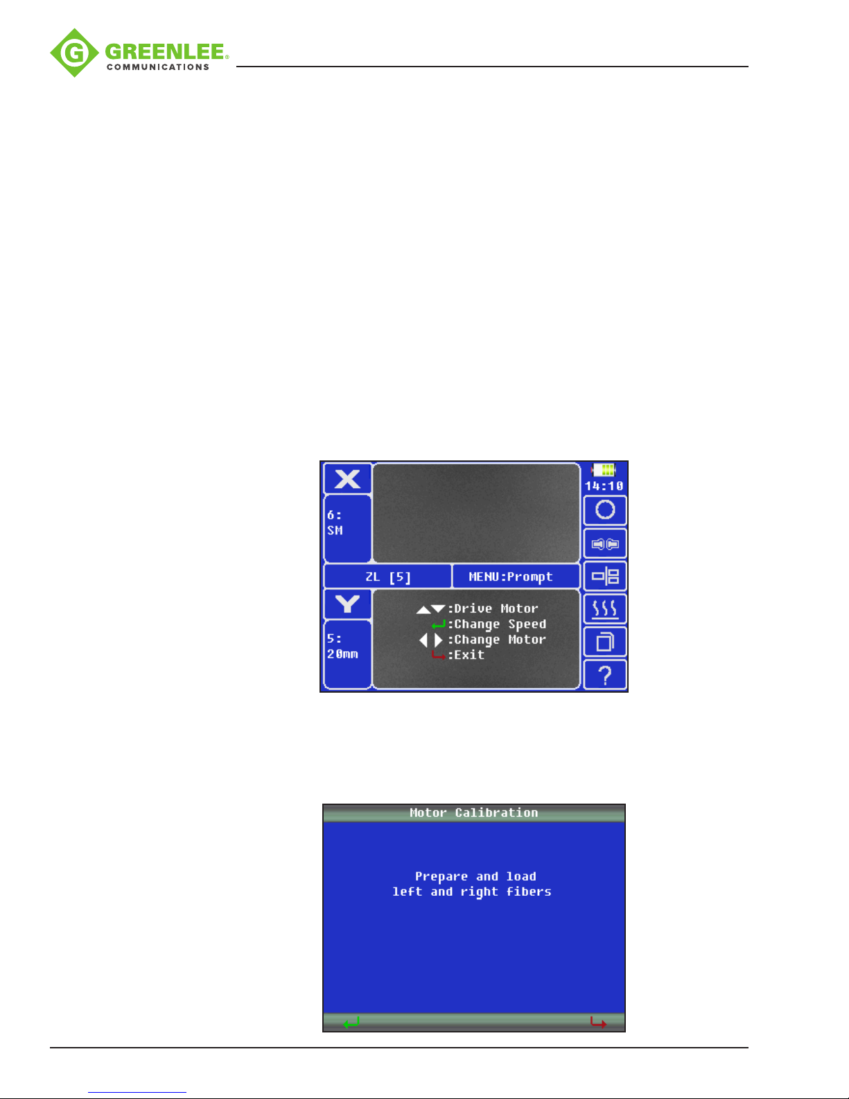
Motor Drive
Used to manually control the motors.
1. Press p or q to move to the selected drive motor.
2. Press 8 to change the speed of the motor.
3. Press t or u to select the motor.
4. Press 9 to exit.
Motor Calibration
Used to auto adjust the motor’s position.
1. Prepare and load left and right bers.
2. Press 8 and wait for the splicer to automatically calibrate the motor positions.
Greenlee / A Textron Company 4455 Boeing Dr. • Rockford, IL 61109-2988 USA • 815-397-7070
28
Page 29
910FS Splicer
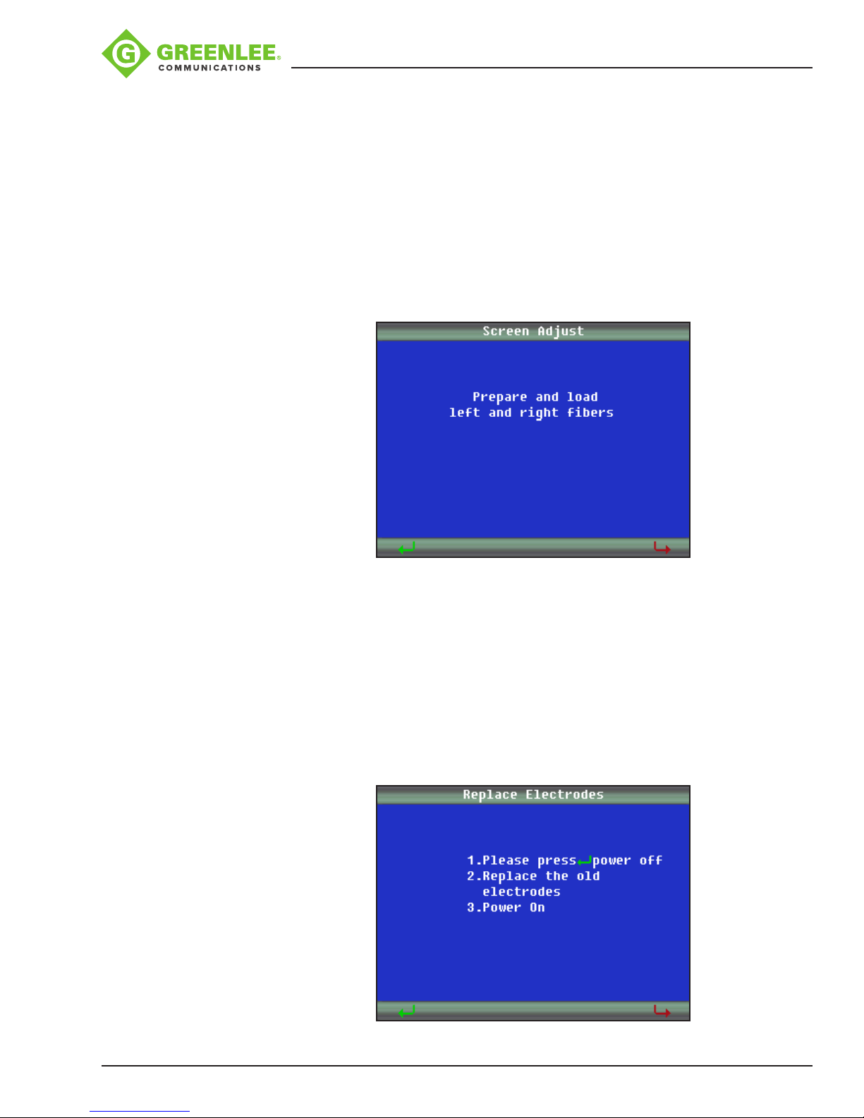
Screen Adjust
Used to adjust the ber position when the bers are displayed outside of the displayed
screen boundaries.
1. Prepare and load left and right bers.
2. Press 8 and then press p and q to switch between X and Y screen views.
3. Press p and q to adjust the ber positions.
4. Press 8 to conrm modication.
5. Press 9 to exit.
Replace Electrodes
1. Turn splicer OFF.
2. Replace the electrodes.
3. Power splicer ON.
4. Select “Replace Electrodes” from menu.
5. Follow on-screen prompts. (This process may take 10 minutes.)
Greenlee / A Textron Company 4455 Boeing Dr. • Rockford, IL 61109-2988 USA • 815-397-7070
29
Page 30
910FS Splicer
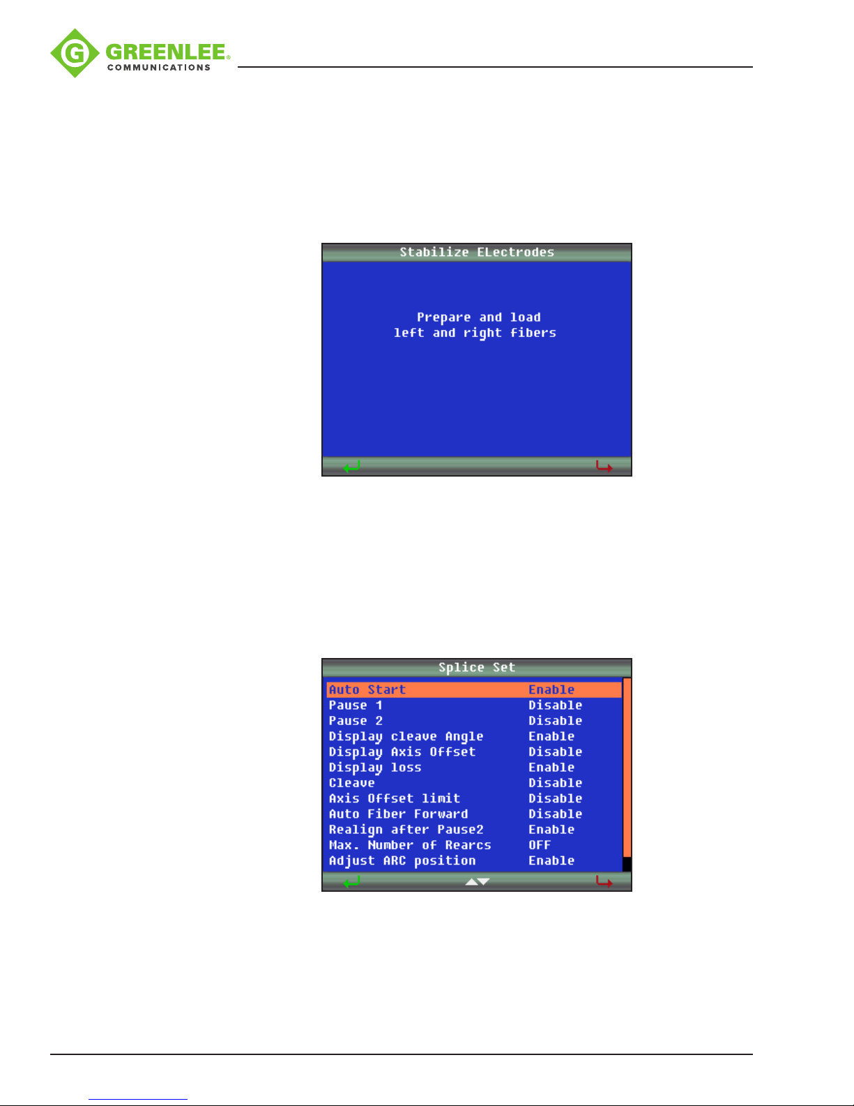
Stabilize Electrodes
Perform this function when the splicer is not performing properly and/or when the arc
display is not a uniform light pattern.
1. Prepare and load left and right bers.
2. Press 8 and wait for the splicer to automatically stabilize the electrodes.
Splice Set
Splice setting options include splicing control, display settings, and splice limit settings
for all splice proles.
Navigate to the “Splice Set” icon and press 8 .
Each menu item can be enabled or disabled per the user’s preference.
Greenlee / A Textron Company 4455 Boeing Dr. • Rockford, IL 61109-2988 USA • 815-397-7070
30
Page 31
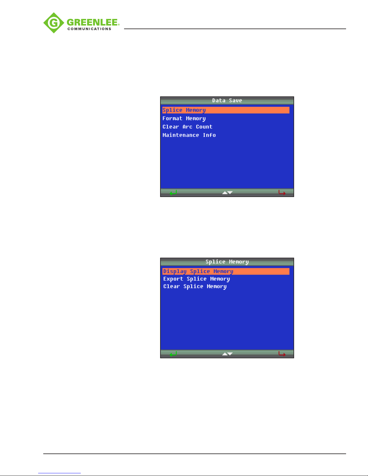
Data Save
910FS Splicer
The 910FS stores up to 5000 splicing results, which can be downloaded via the
USBport.
Navigate to the “Data Save” icon and press 8 to access.
Splice Memory
The Splice Memory function allows the user to display, export, and clear splice memory.
Use pandq to select “Splice Memory” in Data Save menu, and press 8 to conrm.
Greenlee / A Textron Company 4455 Boeing Dr. • Rockford, IL 61109-2988 USA • 815-397-7070
31
Page 32
910FS Splicer
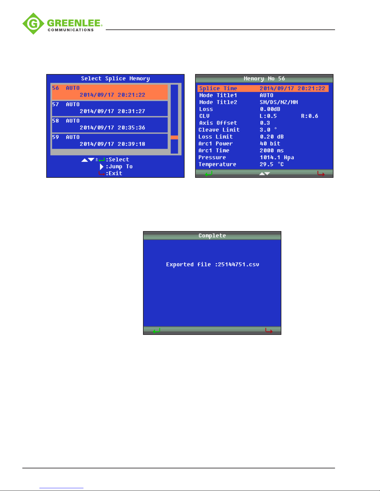
Enter “Display Splice Memory” menu to browse splice results. Use pandq to select
splice result, and press 8 to view details. Press 9 to exit.
Enter “Clear Splice Memory” menu to delete splice results. Use t and u to switch
between Start and End number of splice results. Use pandq to change value.
Press 8 to conrm, and press 9 to exit.
Format Memory
The Format Memory function allows the user to format the entire memory. Press 8 to
conrm, and press 9 to exit.
Clear Arc Count
The Clear Arc Count function allows the user to clear current arc counts from the last
clearance. Press 8 to conrm, and press 9 to exit.
Greenlee / A Textron Company 4455 Boeing Dr. • Rockford, IL 61109-2988 USA • 815-397-7070
32
Page 33
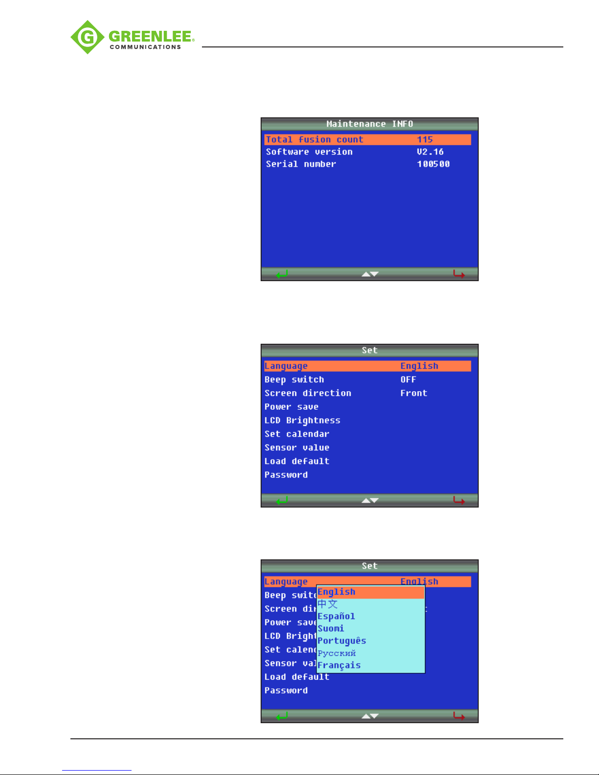
Set
910FS Splicer
Maintenance INFO
The Maintenance INFO function allows the user to check total fusion count, software
version, and serial number information.
This menu is used to set system settings.
Language
Press pandq to set the desired language.
Greenlee / A Textron Company 4455 Boeing Dr. • Rockford, IL 61109-2988 USA • 815-397-7070
33
Page 34
910FS Splicer
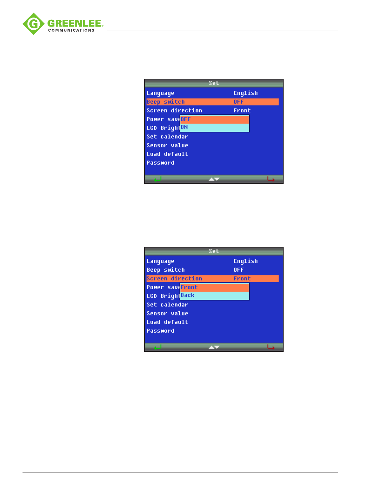
Beep Switch
The Beep Switch function allows the user to enable or disable the splicer beeper.
Screen Direction
The Screen Direction function allows the user to change the display direction for frontor back-facing position.
Greenlee / A Textron Company 4455 Boeing Dr. • Rockford, IL 61109-2988 USA • 815-397-7070
34
Page 35
910FS Splicer
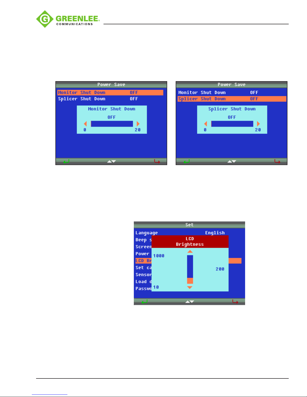
Power Save
The Power Save function conserves energy by turning off the power supply to the
LCD monitor if the splicer performs no operation after a certain period of time (0 to
20minutes adjustable). The LED indicator turns on after Power Save is enabled. Press
any key to turn the LCD monitor back on. The splicer can also be set to automatically
turn off after a certain period of time without operation (0 to 20 minutes adjustable).
LCD Brightness
In the “Ready” interface after the splicer is powered ON, press 8 to enter the splicer
menu. Use p and q to select the “Set” icon, and then navigate to the “LCD Brightness”
tab. Use p and q to adjust the brightness. Then press 8 to conrm.
Greenlee / A Textron Company 4455 Boeing Dr. • Rockford, IL 61109-2988 USA • 815-397-7070
35
Page 36
910FS Splicer
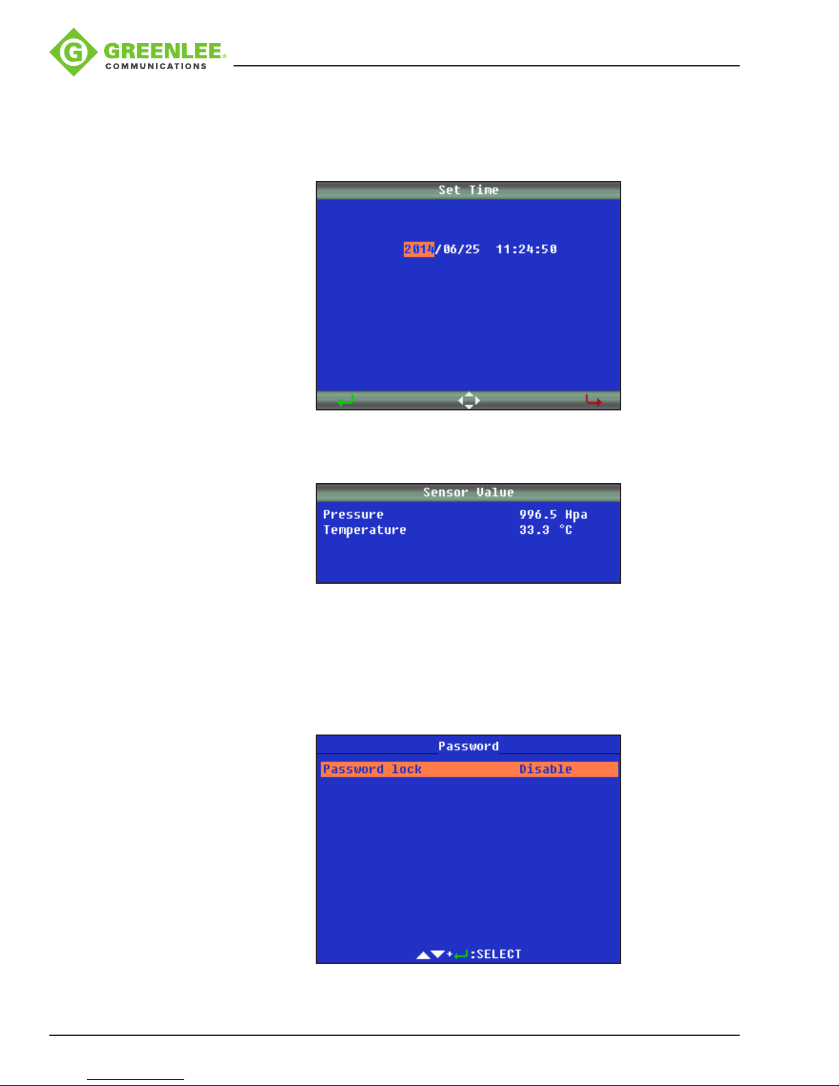
Set Calendar
The Set Calendar function allows the user to set date and time information. Press
toru to select the item to adjust, and press porq to increase or decrease the value.
Press 8 to conrm.
Sensor Value
Displays pressure (XXX Hpa), and temperature (XXX °C).
Load Default
Press 8 to restore the 910FS to default.
Password
Press 8 to enter the “Password” menu. Select “Password Lock”, and press 8 to
enable or disable password function.
Greenlee / A Textron Company 4455 Boeing Dr. • Rockford, IL 61109-2988 USA • 815-397-7070
36
Page 37
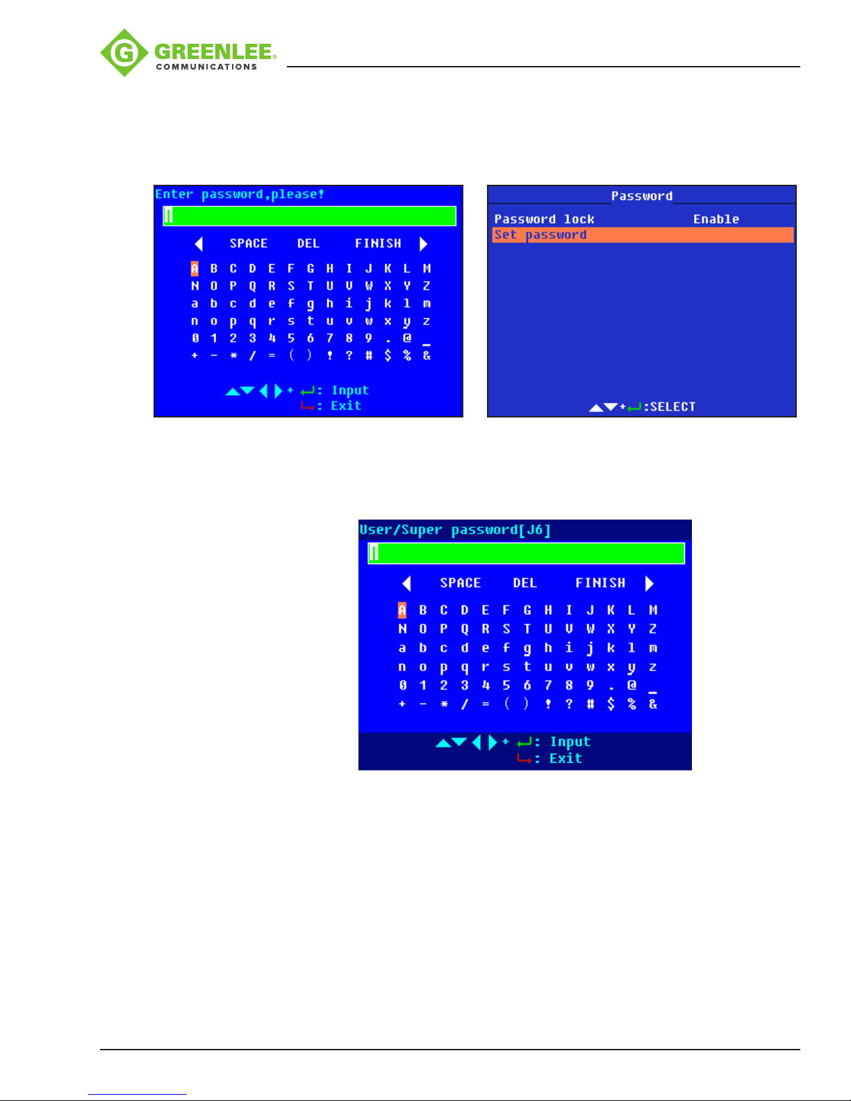
910FS Splicer
When the password function is enabled, select “Set Password” and press 8 to set the
password. Use pqt u to select characters, add spaces, delete characters, or conrm.
(The password max. length is 8, and it can be uppercase letters, lowercase letters,
numbers, or symbols ). Finish setting by selecting “FINISH”.
When the splicer is restarted, the password interface is displayed. Customer can use the
password to unlock.
To cancel the password function, select “Set password”, and then select “FINISH”
(inputnothing for password).
For service:
In the password interface, there is “Super password,” and the “[XX]” following is the
coordinate of “super-password.xlsx.” By using the super password, the user or service
staff can unlock the splicer to renew the password. The super password is obtained
from Greenlee customer service. For each restart, the [XX] is changed, so the user
cannot use the last super password again and needs to contact customer service.
Greenlee / A Textron Company 4455 Boeing Dr. • Rockford, IL 61109-2988 USA • 815-397-7070
37
Page 38
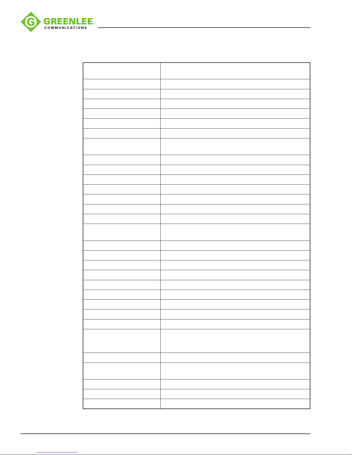
Section 4. Specifications
Applicable Fibers SM (ITU-T G.652), MM (ITU-T G.651), DS (ITU-T G.653),
Fiber Cleaved Length 10 mm
Cladding Diameter 80-150 μm
Coating Diameter 100-1000 μm
Fiber Count Single
Fiber Aligning Method Auto Core alignment
Return Loss ≥60 dB
Actual Average Splice Loss 0.02 dB (SM), 0.01 dB (MM),
Splicing Mode 60 preset/user-denable modes
Splicing Time 9 seconds in standard SM, 12 seconds in AUTO modes
Arc Calibration Mode Automatic and Manual
910FS Splicer
NZDS/LEAF (ITU-T G.655), BIF (ITU-T G.657)
0.04 dB (DS), 0.04 dB (NZDS, LEAF, and BIF)*
Protection Sleeve Length 60 mm, 40 mm and micro sleeves
Storage of Splice Results 5000 results
Tension Test 2 N
Fiber Display Magnication 240X
Tube Heating Mode 20 preset and user denable modes;
adjustable 0–240 seconds
Attenuator Mode 0.1 to 15 dB
Electrode Life 3000 splices
Splices per Battery Charge 360
Tube Heating Time 36 seconds typical
Splicing/Heating Times 250 cycles (splice/tube heat) typical
Display 5.7 inch color turn-over LCD
Connectivity RS-232/USB 2.0
Ingress Protection IP5X
Drop Test 80cm onto bottom axis
Operating Condition 0-5000 m (0-16,400 ft) above sea level; 0 to 95% RH;
-10 to 50 °C (14 to 122 °F): Maximum wind velocity of
15 m/s
Storage Condition -20 to 70 °C (-4 to 158 °F); 0 to 95% RH
Power Supply North America AC adapter (100-240 VAC);
Weight 2.6 kg (5.72 lb) including battery
Dimensions (HxWxT) 180x160x155 mm (7.1 x 6.3 x 6.1 in)
Splice-on Connector SC, LC, FC, and ST
* Insertion loss is for cut and re-splice of identical bers.
Greenlee / A Textron Company 4455 Boeing Dr. • Rockford, IL 61109-2988 USA • 815-397-7070
Li battery (6600 mAh)
38
Page 39
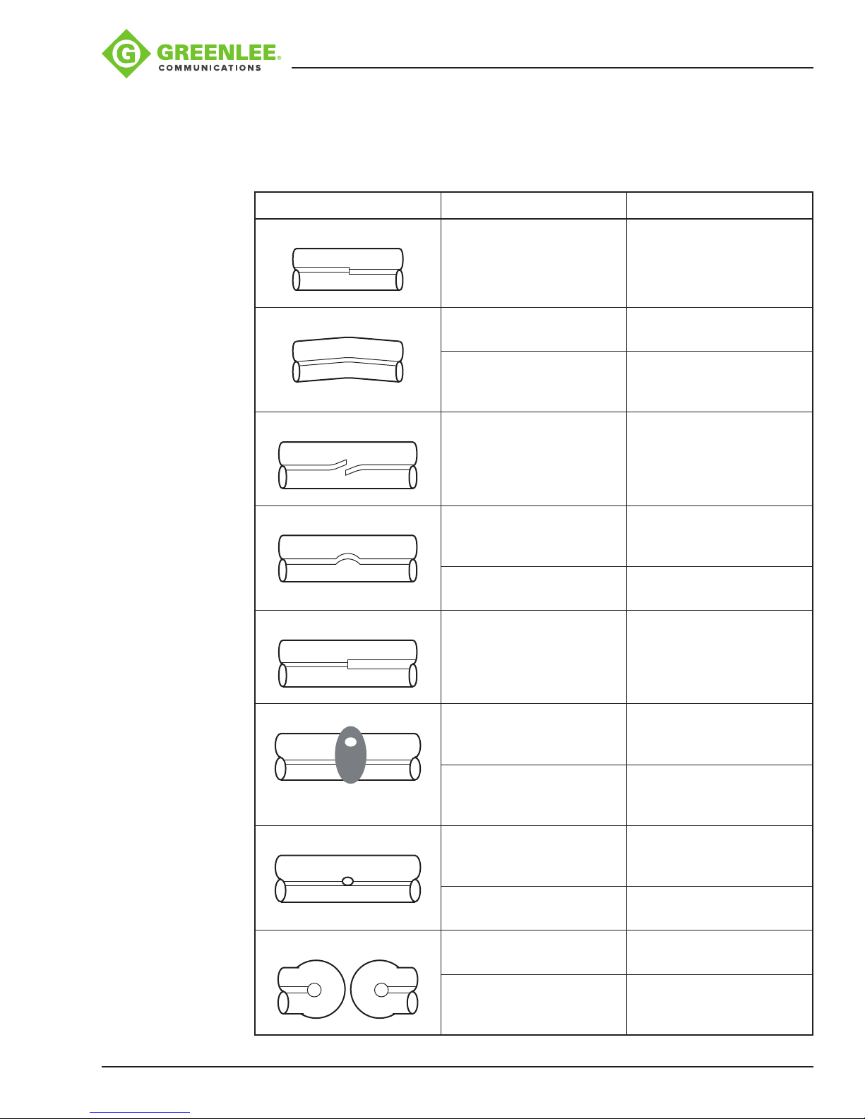
Section 5. Troubleshooting
High Splice Loss Cause and Remedy
Symptom Cause Remedy
910FS Splicer
Core axial offset Dust on V-groove or ber
clamp chip.
Core angle Dust on V-groove or ber
clamp chip damaged.
Bad ber end-face quality. Check if ber cleaver
Core step Dust on V-groove or ber
clamp chip.
Core curve Bad ber end-face quality. Check if ber cleaver
Prefuse power too low, or
prefuse time too short.
MFD mismatch Arc power too low. Increase “Arc Power” and/
Clean V-groove and ber
clamp chip.
Clean V-groove and ber.
Check clamp chip.
is clean and in good
condition.
Clean V-groove and ber
clamp chip.
is clean and in good
condition.
Increase “Prefuse Power”
and/or “Prefuse Time”.
or “Arc Time”.
Greenlee / A Textron Company 4455 Boeing Dr. • Rockford, IL 61109-2988 USA • 815-397-7070
Combustion Bad ber end-face quality. Check if ber cleaver
is clean and in good
condition.
Dust still present after
cleaning ber or cleaning
arc.
Bubbles Bad ber end-face quality. Check if ber cleaver
Prefuse power too low, or
prefuse time too short.
Separation Fiber stufng too small. Perform “Motor
Prefuse power too high, or
prefuse time too long.
39
Clean ber thoroughly and/
or increase “Cleaning Arc
Time.”
is clean and in good
condition.
Increase “Prefuse Power”
and/or “Prefuse Time”.
Calibration”.
Decrease “Prefuse Power”
and/or “Prefuse Time”.
continued on next page
Page 40
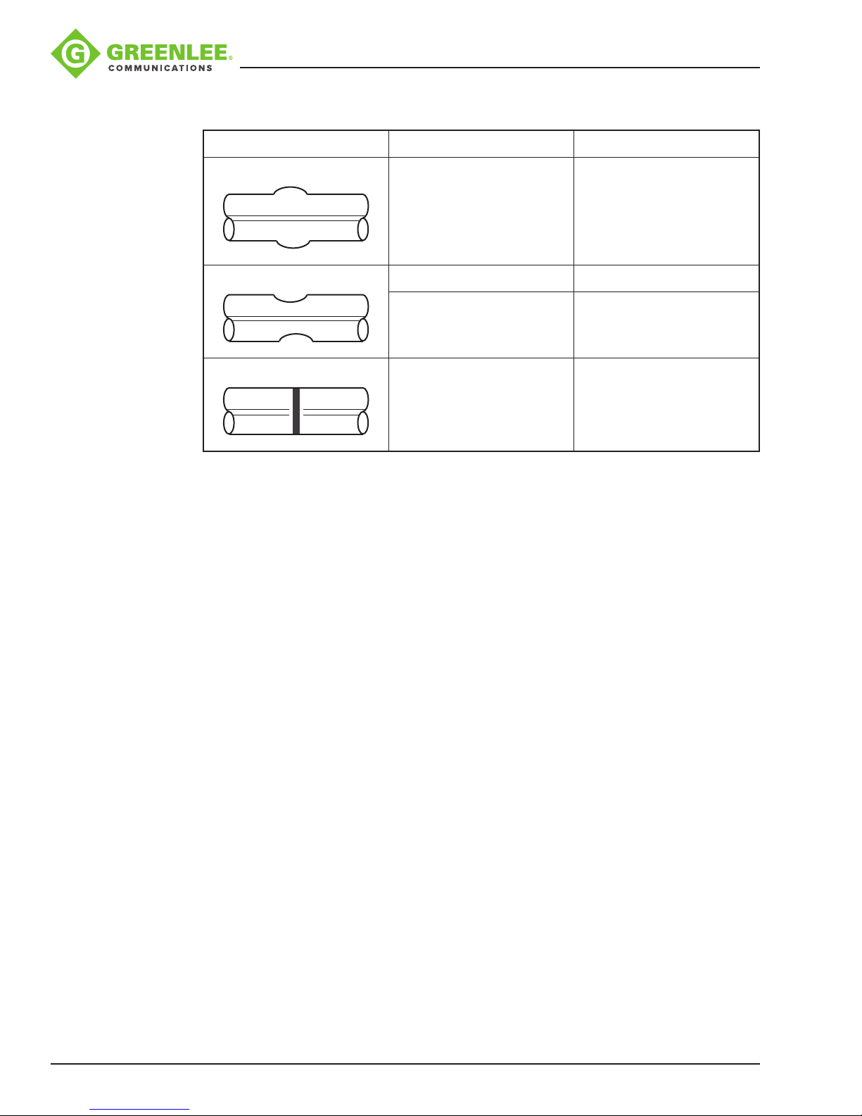
High Splice Loss Cause and Remedy (cont’d)
Symptom Cause Remedy
Fat Fiber stufng too much. Decrease “Overlap”
and perform “Motor
Calibration”.
Thin Arc power not adequate. Perform “Arc Calibration”.
910FS Splicer
Some arc parameters not
adequate.
Line Some arc parameters not
adequate.
Note: A vertical line sometimes appears at the spice point when MM bers or dissimilar
bers (different diameters) are spliced. This does not affect splice quality, such as splice
loss or tensile strength.
Note: If the user is getting high splice losses, make sure that the 910FS is not in Splice
Mode #10, which is used to make attenuator splices.
Adjust “Prefuse Power”,
“Prefuse Time”, or
“Overlap”.
Adjust “Prefuse Power”,
“Prefuse Time”, or
“Overlap”.
Cleaver
If the cleaver does not cleave, make sure that the 250 micron acrylic coating is being
removed during the ber stripping process.
Greenlee / A Textron Company 4455 Boeing Dr. • Rockford, IL 61109-2988 USA • 815-397-7070
40
Page 41

Error Messages
Error Message Reason Solution
910FS Splicer
Left/Right/L-R ber set
too close!
Left/Right/L-R ber set
too far!
Reset Left/Right bers!
Clear Left/Right bers! • Dust or dirt is on the objective lens
Left/Right ber X/Y set
error!
X/Y Motor out of range!
• The ber end-face is placed on the
electrode centerline, or beyond it.
• The cleave length (bare ber part) is
too long.
• Dust or dirt is on the objective lens
or the wind protector mirror.
or the wind protector mirror.
• “Cleaning Arc” time is too short or
OFF.
• Splicing indistinct core bers with
the SM or DS modes.
• “Align” is set to “Core” to splice
indistinct core bers when using
other splice modes.
• “Focus” is incorrectly set when
using other splice modes.
• The ber is not set correctly at the
bottom of the V-groove. The ber
position is out of focus range.
• Dust or dirt is on the ber surface
resulting in focus failure.
• Dust or dirt is on the objective lens
or the wind protector mirror.
• Conrm the setting position of the
stripped ber end on the ber cleaver.
Check the cleave length.
• Clean the lens or the mirror when dust or
dirt exists.
• Completely prepare the ber again (strip,
clean, and cleave).
• Clean the lens or the mirror if dust or dirt
exists.
• Set the “Cleaning Arc” time to “30ms.”
When splicing carbon-coated bers, set
to “100ms.”
• Use the MM mode to splice indistinct
core bers (i.e., MM ber).
• Set “Align” to “Clad” to splice indistinct
bers (i.e., MM ber).
• Set “Focus” to “Edge” to splice indistinct
core bers (i.e., MM ber). To splice
distinct core bers, enter “Auto” or the
correct focus value.
• Press , and re-position the ber to seat
it correctly at the bottom of the V-groove.
• If bers are not shown, use “screen
adjust.” Follow the procedure displayed
to enable the entire ber to be displayed.
• Completely prepare the ber again (strip,
clean, and cleave).
• Clean the lens or the mirror if dust or dirt
exists.
Cover is open! The wind protector is opened during
splicing operation.
Left/Right/L-R ber
angle errors, shape
errors and clear left &
right errors
Greenlee / A Textron Company 4455 Boeing Dr. • Rockford, IL 61109-2988 USA • 815-397-7070
• “Core Angle Limit” is set too low.
• Dust or dirt is on the V-groove or the
clamp chip.
• Bad ber end-face.
Press after closing the wind protector.
• The splicer measures the core angle only
when using other splice modes. Increase
the “Core Angle Limit” to an adequate
limit. (1.0 degree is standard.)
• Clean the V-groove and clamp chip, and
set the bers again. If the error occurs
again, strip, clean, and cleave the bers.
• Check the condition of ber cleaver. If the
blade is worn, rotate the blade to a new
position.
41
Page 42
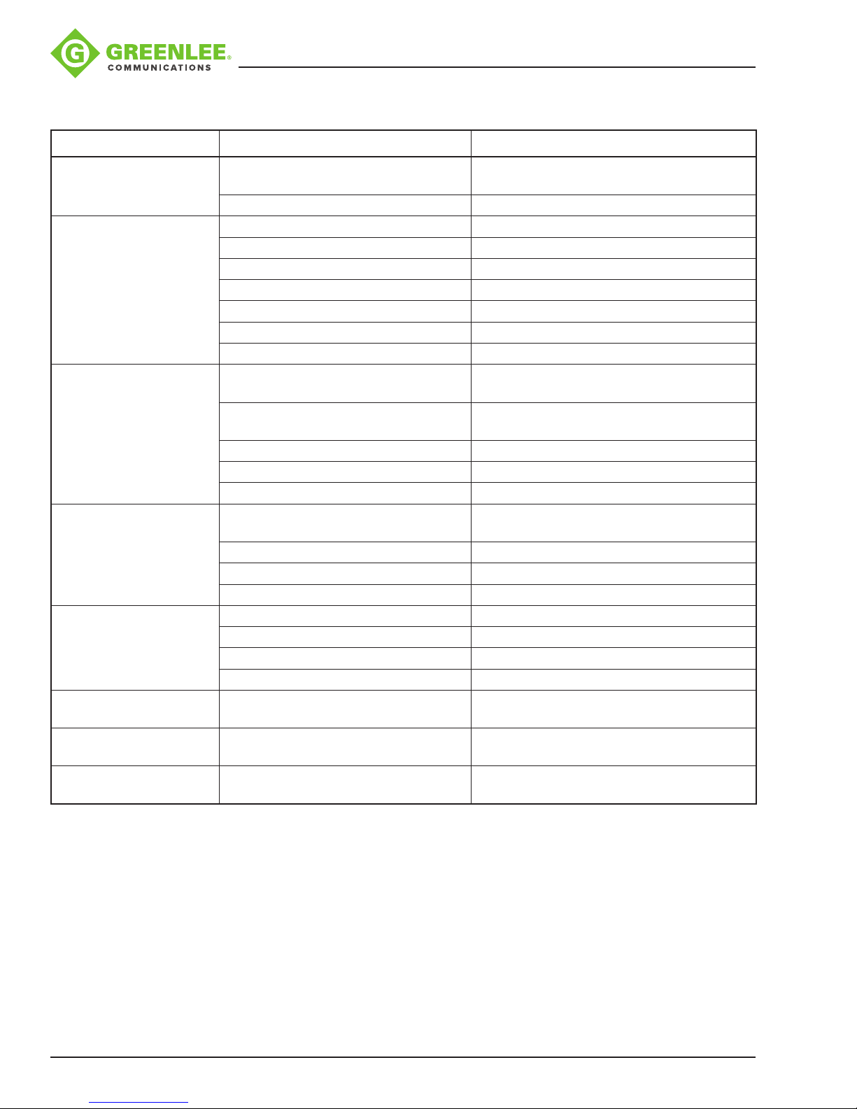
Error Messages (cont’d)
Error Message Reason Solution
910FS Splicer
Display “Wait
Download..”
LEFT_FIBER_DIRTY
RIGHT_FIBER_DIRTY
LR_FIBER_DIRTY
LR_ARC_VALUE_ERR Fibers are dirty, passing the limit of
FIBER_PUSH_ERR Fiber is not in V-groove. Replace ber and check if ber is in the
ARC_OFFSET_TOO_
LARGE
LENS_OFFSET_TOO_
LARGE
COVER_OPEN when the
windshell is closed
Notied to replace
electrodes
ON/OFF and ENTER buttons are held
at the same time.
Component damage – keypad. Keypad replacement required.
Fibers are dirty. Clean ber and recleave.
V-grooves are dirty. Clean V-grooves.
V-grooves are damaged. V-grooves need to be factory replaced.
Fiber presser foot is dirty. Clean presser foot of 910CL.
Fiber adapters are dirty. Clean ber adapters.
Mirrors are dirty. Clean mirrors .
Lenses are dirty. Clean lenses.
checking process.
Cleave angle is too big. Recleave bers to obtain good cleave
Failure to do the arc calibration. Do arc calibration.
Electrodes are oxidized. Clean electrodes or replace with a new pair.
Lenses are dirty. Clean lenses.
Fiber holder is not tight. Reposition the ber.
Backward tension is on ber. Release any tension on ber.
The adapter holder is dirty. Clean the ber adapter holder.
Failure to do the arc calibration. Do arc calibration.
Electrodes position error. Check and or replace electrodes.
Electrodes are broken. Replace electrodes.
Electrodes are oxidized. Replace electrodes.
Fiber is beyond observation range. Perform “Screen Adjust” to allow bers to
The magnet on windshell is missing. Magnet needs to be factory replaced.
Electrodes require calibration or
replacement.
Power off. Power back on.
Clean ber and recleave.
angle.
V-groove.
be displayed on the screen.
Stabilize electrodes as per Menu 3; replace
electrodes.
Greenlee / A Textron Company 4455 Boeing Dr. • Rockford, IL 61109-2988 USA • 815-397-7070
42
Page 43
910FS Splicer
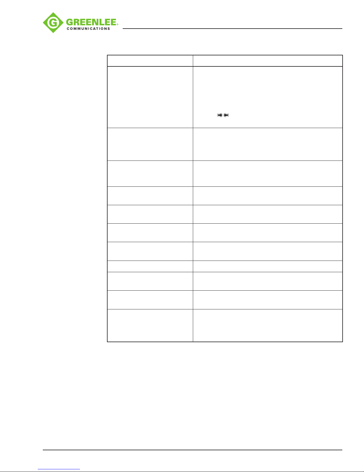
If High Estimated Loss
Reason Solution
Insufcient ber cleaning. Dust or dirt on the ber surface results in bad splice
loss and low tensile strength.
• Clean the ber surface sufciently.
• Do not clean the ber after cleaving to prevent dust
on the ber end-face.
• Avoid any contact with the ber end-face.
• Press to perform an arc calibration as dened
in this instruction manual.
Bad ber end-face. • Check the condition of ber cleaver. If the blade is
worn, rotate the blade to a new position.
• Conrm the “Cleave Limit” setting; 2.0° or less is
recommended.
Dust or dirt is on the V-groove
or the clamp chip.
Dust or dirt is on the lens or
mirror.
Bad electrode condition. Replace the electrodes if they appear worn (rounded
Inadequate arc power. Calibrate the arc power with the “Arc Calibration”
Using unsuitable splice mode. Select a suitable splice mode for the bers to be
“Loss Limit” is set too low. Increase “Loss Limit” to an adequate limit.
Fibers were spliced after Error
was canceled.
Inadequate arc parameters in
other splice modes.
Inadequate estimating
parameters in Other mode.
Dust or dirt on the V-groove or clamp chip causes
poor ber movement during ber adjusting. Clean
them periodically.
If dust or dirt exists, clean the lenses or mirrors.
tip shape), dirty, or bent.
function.
spliced.
Select the appropriate splice mode from the Other
modes.
Conrm the arc parameters are adequate to splice the
bers.
Conrm the estimating parameters are adequate to
estimate the loss. The MFD mismatch function does
not work for certain types of specialty bers. In these
cases, set the “MFD Mismatch” to OFF.
Greenlee / A Textron Company 4455 Boeing Dr. • Rockford, IL 61109-2988 USA • 815-397-7070
43
Page 44
910FS Splicer
Appendix A. 910FS Fusion Splicer Cleaning
Precautions When Cleaning 910FS and 910CL
• Turn off splicer.
• Use only lint-free cotton swabs.
• Use only 99% pure isopropyl alcohol or an approved substitute.
• Do not touch the electrodes.
• Never use compressed air.
• Use the cleaning brush only to clean debris from general working area, never on the
lenses, V-grooves, or mirrors.
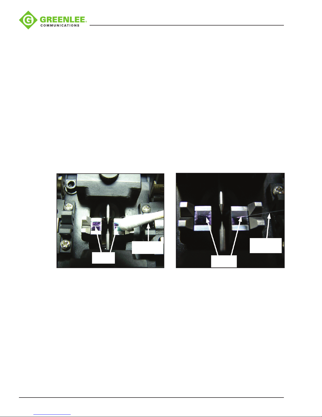
Cleaning V-grooves (recommended daily)
Refer to Figure 1.
Clean the bottom of the V-groove with an isopropyl alcohol-impregnated lint-free cotton
swab. Remove excess alcohol from the V-groove with a clean, dry lint-free cotton swab.
Cleaning
Swab
V-grooves
Figure 1 Figure 2
If the contaminants in the V-groove cannot be removed with an alcohol-impregnated
lint-free cotton swab, use a cleaved ber end-face to dislodge contaminants from the
bottom of the V-groove. Refer to Figure 2. Repeat cleaning the V-grooves as in Figure 1.
V-grooves
Cleaved
Fiber
Cleaning Fiber Clamps (recommended daily)
Refer to Figure 3.
If contaminants are present on the clamps, proper clamping may not occur, resulting
in poor quality splices. The ber clamps should be inspected frequently and cleaned
periodically during normal operation. To clean the ber clamps, do the following:
Clean the surface of the clamps with an alcohol-impregnated lint-free cotton swab.
Remove excess alcohol from the clamps with a clean, dry lint-free cotton swab.
Greenlee / A Textron Company 4455 Boeing Dr. • Rockford, IL 61109-2988 USA • 815-397-7070
44
Page 45
910FS Splicer
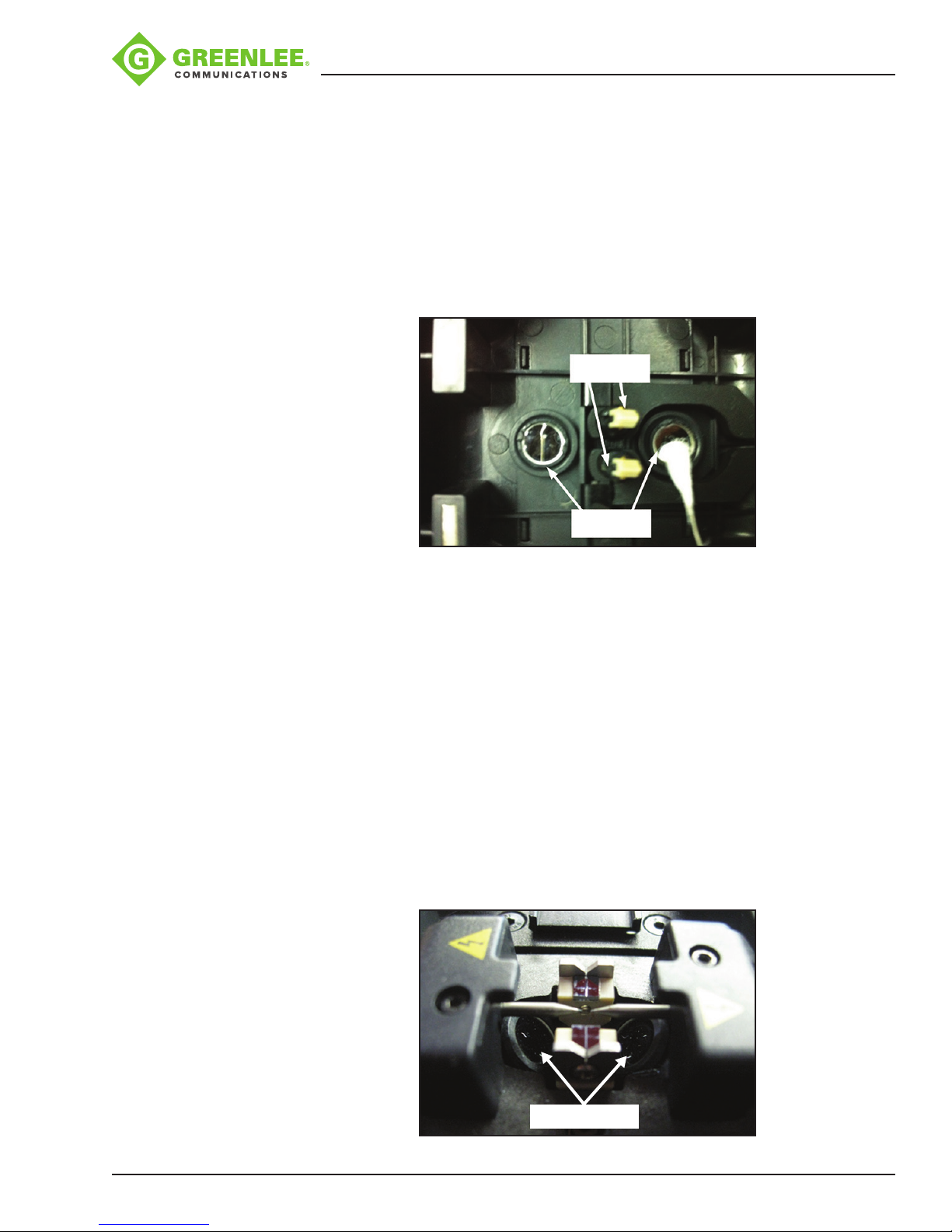
Cleaning Wind Protector Mirrors (recommended daily)
Refer to Figure 3.
If the wind protector mirrors become dirty, the ber core position may be incorrect due
to decreased optical path clarity, resulting in higher splice loss. To clean the mirrors, do
the following.
• Clean the mirror surface with an alcohol-impregnated thin lint-free cotton swab.
Remove excess alcohol from the mirror surface with a clean, dry lint-free cotton
swab.
• Mirror should look clean with no streaks or smudges.
Fiber
Clamps
Wind Shield
Mirrors
Figure 3
Cleaning Objective Lenses (recommended weekly)
Refer to Figure 4.
If the surfaces of the objective lenses become dirty, normal observation of the core
position may be incorrect, resulting in higher splice loss or poor splicer operation.
Therefore, clean both of them at regular intervals. Otherwise, dirt may accumulate and
become impossible to remove. To clean the objective lenses, do the following:
• Before cleaning the objective lenses, always turn off the splicer.
• Gently clean the lenses’ (X-axis and Y-axis) surfaces with a dry lint-free cotton swab.
Using the swab, start at the center of the lens and move the swab in a circular
motion until you spiral out to the edge of the lens surface.
• The lens surface should be clean and free of streaks or smudges.
• Turn on the power and make sure no smudges or streaks are visible on the monitor
screen. Press X/Y to change the screen and check the state of the lens surface on
both the X- and Y-screens.
Greenlee / A Textron Company 4455 Boeing Dr. • Rockford, IL 61109-2988 USA • 815-397-7070
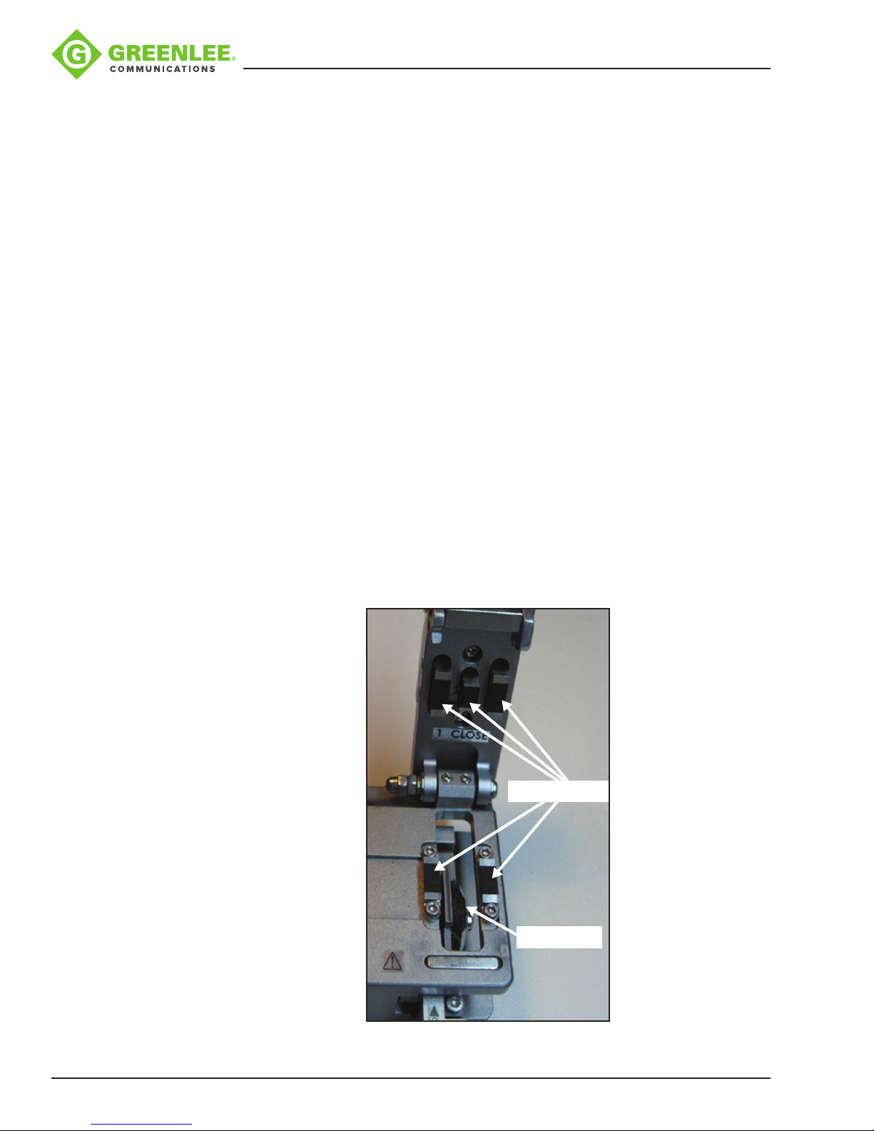
Objective Lenses
Figure 4
45
Page 46
910FS Splicer
NOTE:
• Do not touch the electrodes when cleaning.
• It is recommended to clean the objective lenses when replacing the electrodes.
Cleaning the Electrodes
1. Insert the electrode tip into the hole of the electrode polisher and gently rotate the
electrode.
2. Wipe the electrodes with 99% pure IPA. Do not touch the electrode surface with
your ngers.
3. Re-install the electrodes into the splicer.
4. Perform an arc calibration to calibrate the power to the electrodes.
General Fusion Splicer Cleaning (recommended daily)
• Use the cleaning brush only to clean debris from general working area, never on the
lenses, V-grooves, or mirrors.
• Periodically clean the ber adapters with isopropyl alcohol and a lint-free cotton
swab. Never touch the ber clamping area of the ber adapters.
Cleaning Fiber Cleaver 910CL (recommended daily)
Refer to Figure 5.
If the circular blade or clamp pads of the ber cleaver become contaminated,
the cleaving quality could degrade. This may lead to ber surface or end-face
contamination, resulting in higher splice loss. Clean the circular cleaving blade and
clamp pads with a lint-free cotton swab soaked with isopropyl alcohol.
Fiber Clamps (5)
Greenlee / A Textron Company 4455 Boeing Dr. • Rockford, IL 61109-2988 USA • 815-397-7070
Cleaving Blade
Figure 5
46
Page 47
Appendix B. Practice Splicing
General Precautions
• Refer to the 910FS and 910CL user manual.
• Clean all connectors before making a connection.
It is highly recommended that new 910FS users use the AUTO mode splicing
profile until they have become proficient at splicing.
Checking the Splice Quality of the 910FS
The user should practice splicing with the type of ber that they will use in their
installation before attempting to splice bers in those installations.
The following procedure should be used to practice fusion splicing ber cables:
1. Identify the eld ber type by consulting the ber manufacturer’s data sheet.
2. Obtain an approximately 10 m length of ber (same as eld ber).
3. Determine if this ber type has a pre-programmed splicing prole in the 910FS.
Usethis prole for splicing.
910FS Splicer
Optical Source
4. If there is not an exact matching splice prole, use the AUTO mode splicing prole.
5. Splice a ber pigtail with a suitable connector for their source/power meter of like
ber to one end of the 10 m ber.
6. Splice a ber pigtail with a suitable connector for the source/power meter of like
ber to the other end of the 10 m ber.
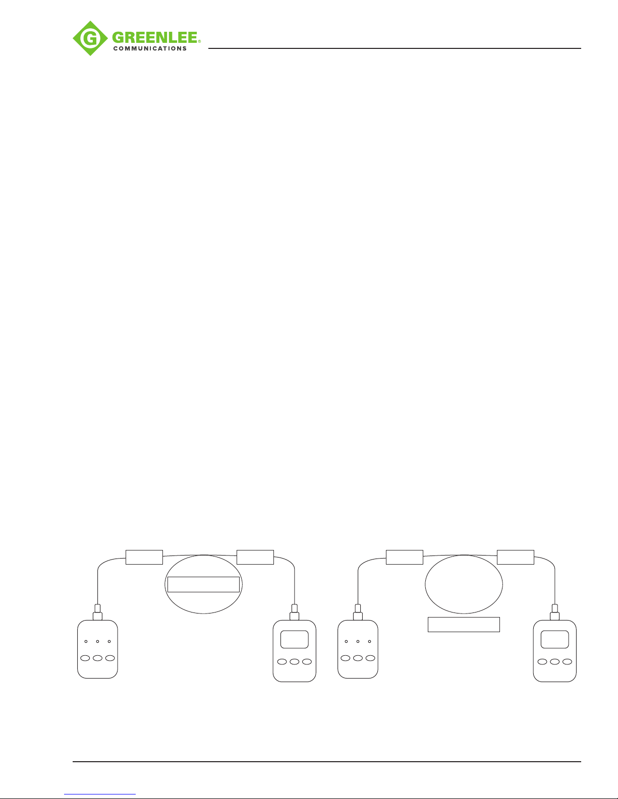
7. Connect a laser (SM) or LED (MM) source to one end of the ber and a power meter
to the other end of the ber. Refer to Figure 1.
8. Zero the power meter. Refer to Figure 2.
9. Cut the 10 m piece of ber in the middle and splice it back together. The power
meter should read 0dB PLUS allowable splice loss X2.
10. The splicing technician should repeat step 9 until they are able to reliably splice
using the desired ber.
SPLICE SPLICE
10 m of Test Fiber
Power
Meter
Optical Source
SPLICE SPLICE
10 m of Test Fiber
0 dB
st
1
λ 2nd λ
On/Off
Figure 1 Figure 2
Greenlee / A Textron Company 4455 Boeing Dr. • Rockford, IL 61109-2988 USA • 815-397-7070
On/Off
λ dB/dBm
47
On/Off
st
1
λ 2nd λ
On/Off
λ dB/dBm
Page 48
910FS Splicer
Testing Splicing Splice-on Connectors (SOC)
The 910FS can fusion splice SOC using the universal SOC adapters. Be sure to select
the correct SOC to match the eld bers before splicing.
The following procedure should be used to practice fusion splicing with SOC:
1. Identify the eld ber type by consulting the ber manufacturer’s data sheet.
2. Obtain a “ber patch cord” with same ber and connector style as the SOC that will
be used.
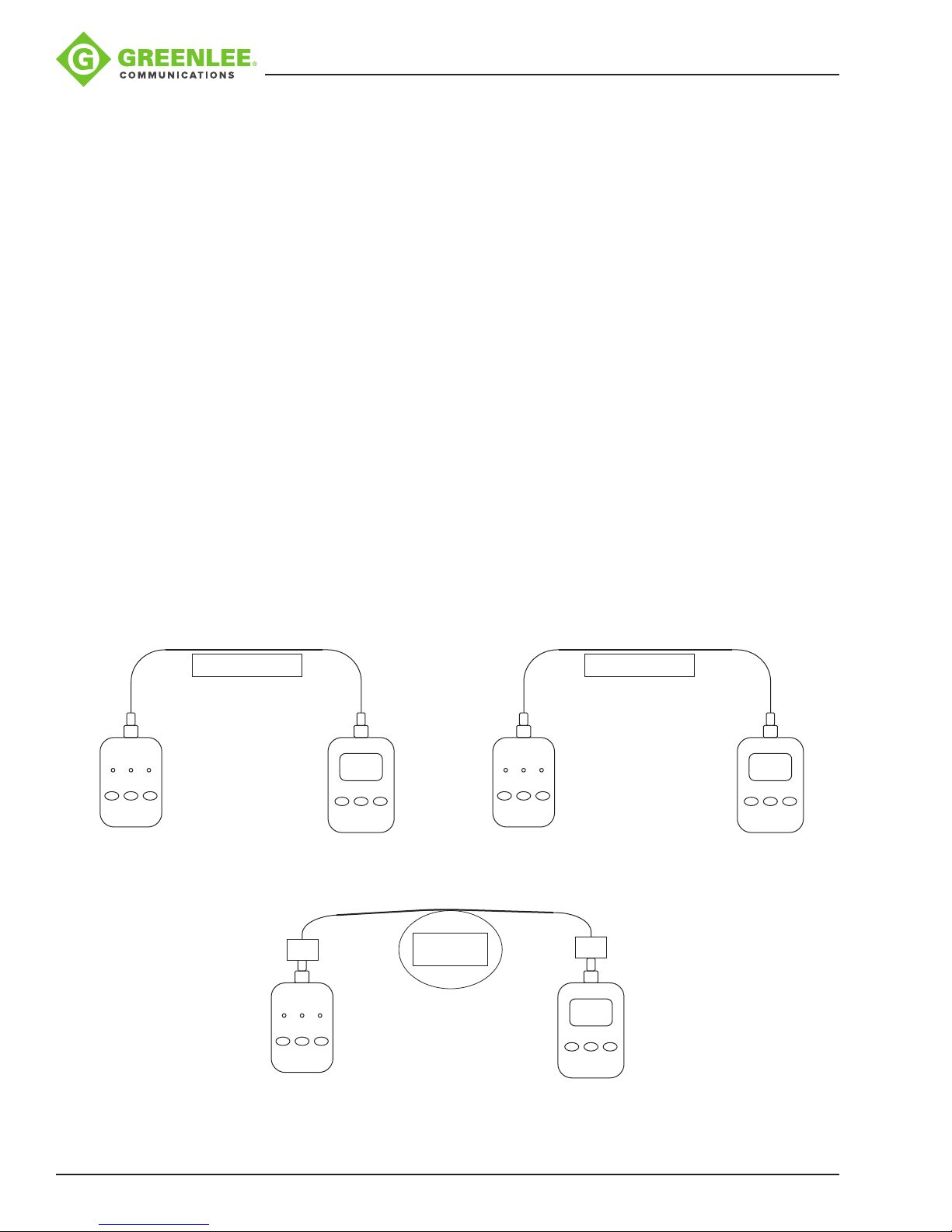
3. Connect a laser (SM) or LED (MM) source to one end of the ber and a power meter
to the other end of the ber. Refer to Figure 3.
4. Zero the power meter. Refer to Figure 4.
5. Obtain an approximately 10 m length of ber (same as the eld ber).
6. Determine if this ber type has a pre-programmed splicing prole in the 910FS.
Usethis prole for splicing.
7. If there is not an exact matching splice prole, use the AUTO mode splicing prole.
8. Splice a SOC to each end of the ber. This will be called the “SOC spliced patch
cord.”
Optical Source
st
1
λ 2nd λ
On/Off
9. Replace the “ber patch cord” with the “SOC spliced patch cord.” The power meter
should read 0dB PLUS allowable splice loss X2. Refer to Figure 5.
10. The splicing technician should repeat steps 8 and 9 until they are able to reliably
splice using the SOC.
Fiber Patch Cord
On/Off
Power
Meter
λ dB/dBm
Optical Source
st
1
λ 2nd λ
On/Off
Fiber Patch Cord
On/Off
0 dB
λ dB/dBm
Figure 3 Figure 4
SOC
SOC Spliced
Patch Cord
SOC
Optical Source
st
1
λ 2nd λ
On/Off
Greenlee / A Textron Company 4455 Boeing Dr. • Rockford, IL 61109-2988 USA • 815-397-7070
Figure 5
48
On/Off
0 dB
λ dB/dBm
Page 49
Appendix C. Greenlee Splice-on Connectors
Note: This splice-on connector is compatible with 900 µm optical ber.
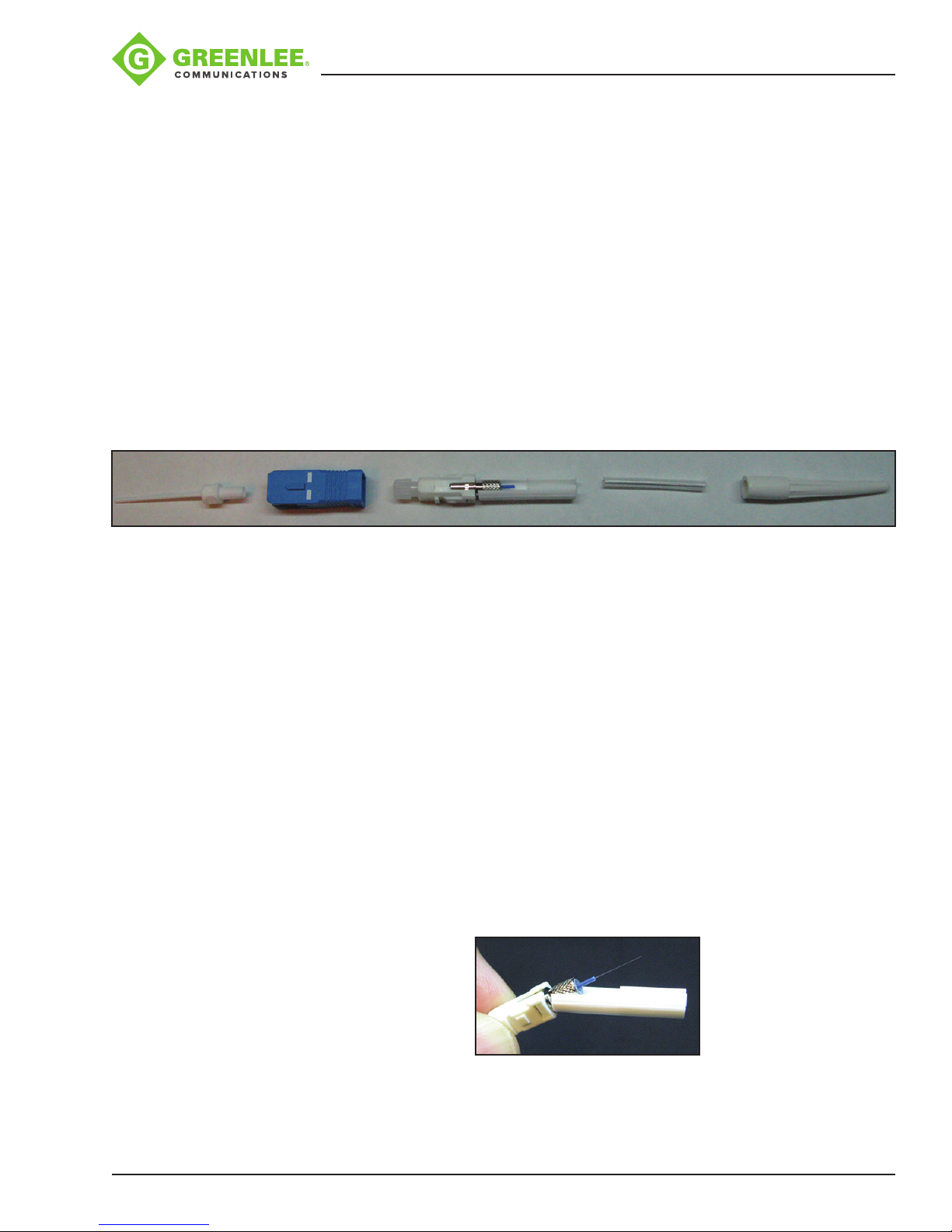
Greenlee splice-on connector contains the following items:
A. (1) Handle, each kit contains a limited number
B. (1) Outer housing (SC style only)
C. (1) Splice-on connector (SOC) pigtail with cleave protector and ber alignment
sleeve
D. (1) 27 mm mini splice sleeve
E. (1) Universal strain relief boot
F. (1) Fiber positioning tool (not pictured)
Note: If ber alignment sleeve has become separated from the SOC body, do not
attempt to re-install; discard it.
910FS Splicer
A B C D E
Cable Preparation
Slide the 900 μm strain relief boot and then the 27 mm mini splice protective sleeve over
the 900μm eld ber. Use the 910CL to cleave the eld ber. Insert the ber adapter
with the cleaved ber into the left-hand side of the 910FS fusion splicer. Make sure to
butt the 900 μm buffer up to the edge of the ber adapter. This will ensure that the mini
splice sleeve will adhere to both sides of the 900 μm buffer.
Installation
1. Disable the “Proof Test” on the fusion splicer.
2. Remove the factory dust cap from the connector.
Note: The extended dust cap may be placed on at this time, if so desired, to aid in
the transfer of the connector. DO NOT LEAVE THE EXTENDED DUST CAP ON THE
CONNECTOR, INSIDE THE FUSION SPLICE MACHINE.
3. While holding the connector rmly, pull down on the cleave protector to remove it
from the connector (Figure 1).
Note: Do not touch the cleaved ber stub with the protector or your ngers as this
may damage the factory cleave.
Greenlee / A Textron Company 4455 Boeing Dr. • Rockford, IL 61109-2988 USA • 815-397-7070
Figure 1
49
Page 50
910FS Splicer
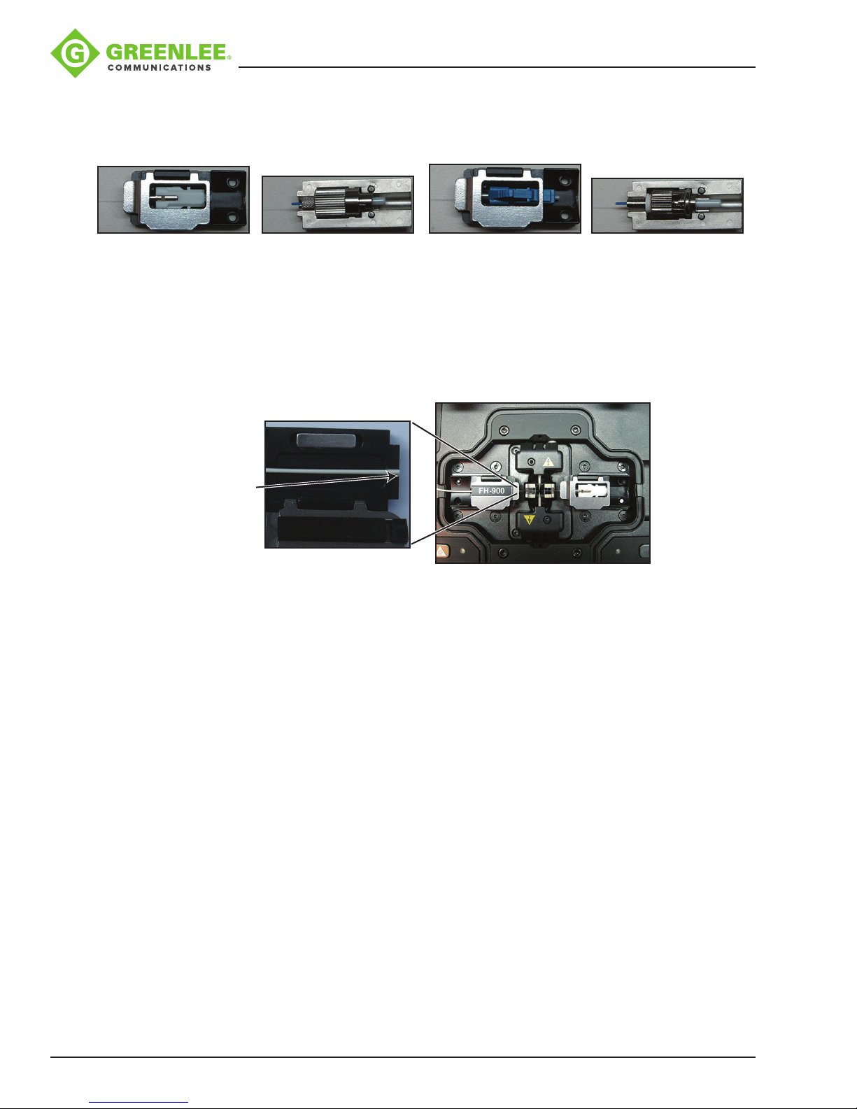
4. Insert the connector into the universal splice-on connector holder so that the back
end of the connector is ush with the end of the holder (Figures 2-5). Once aligned
properly, the connector should t freely into the holder with no force required.
Figure 2 (SC) Figure 3 (FC) Figure 4 (LC) Figure 5 (ST)
5. Insert the holder into the right-hand side of the splicer (Figure 6), making sure that
the ber stub lays properly into the V-groove block of the splicer. You may use the
ber positioning tool to help align the ber in the V-groove. The ber for FC and ST
splice-on connectors must have the ber laying in the end of the ber groove in the
V-groove. The ber positioning tool can be used to align the ber with the V-groove.
Turning the ber and/or the connector may also be necessary to accomplish this.
The FC/ST ber adapter may also need to be twisted slightly to ensure that the ber
is aligned with the V-groove.
Note: Make sure that
the edge of the 900
micron tight buffer is
even with the edge of
the 900 micron fiber
adapter.
Figure 6
Note: Remove the
extended dust cap
before initiating the
fusion splice.
6. Perform the fusion splice as described in the fusion splicer manufacturer’s
instructions.
7. Once the fusion splicing cycle is completed, remove the connector from the splicer
and slide the splice protection sleeve up to cover the splice. Make sure that the
splice protector is positoned against the connector body.
Note: The extended cap may be put in place now to aid in the transfer to the splice
sleeve oven.
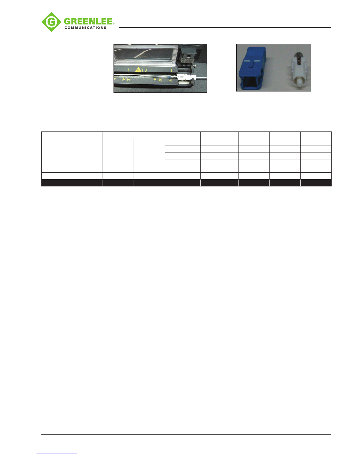
8. Transfer the splice to the splice sleeve heat oven on the right-hand side (Figure
7). Verify the position of the splice sleeve is butted up against the metal portion of
the splice-on connector. Use the 60 mm heater mode #1 with center and edges
activated. Press the HEAT button to run the shrink cycle.
9. Verify that the splice protection sleeve is completely shrunk onto the ber to avoid
the end catching on the strain relief boot. If the splice sleeve is not completely
shrunk, then place it back in the sleeve oven and initiate a second heat cycle.
Note: Make sure that the splice sleeve has fully cooled before sliding the strain relief
boot into place. For SC connectors, install the outer housing onto the connector,
being sure to align the angled corners of the inner housing with those of the outer
housing (Figure 8).
Greenlee / A Textron Company 4455 Boeing Dr. • Rockford, IL 61109-2988 USA • 815-397-7070
50
Page 51
910FS Splicer
Figure 7 Figure 8
Compatibility Chart
The Greenlee SOC adapter allows the Greenlee 900 micron SOC to be used in competitors’ fusion splicers.
Manufacturer AFL Sumitomo Fitel INNO FIS
Model FSM11 (S/M) FSM-17S FSM-18S Type-25e (U/S/M) S122(A/C/M/) IFS10 CA3
FSM-19S Type-39FH S121 (A/M) IFS15
FSM-60(S/R) Type-46 S123 (C/M)
FSM-70(S/R) Type-66 S153
Quantum (Q101-CA) S178A
Compatible fiberTOOLS™ SOCs All versions SC and LC only SC, LC and ST only All versions All versions All versions All versions
Greenlee SOC Adapter 52075260 52075260 52075260 52075282 52075281 52075283 52075284
Visit www.greenleecommunications.com for an updated compatibility list and a video demonstration of the SOC.
Greenlee / A Textron Company 4455 Boeing Dr. • Rockford, IL 61109-2988 USA • 815-397-7070
51
Page 52

Warranty
Greenlee Textron Inc. warrants to the original purchaser of
these goods for use that these products will be free from
defects in workmanship and material for one year. This warranty is subject to the same terms and conditions contained
in Greenlee Textron Inc.’s standard one-year limited warranty.
For all Test Instrument repairs, contact Customer Service at
800-642-2155 or 760-598-8900 and request a Return
Authorization.
For items not covered under warranty (such as items
dropped, abused, etc.), a repair cost quote is available upon
request.
Note: Prior to returning any test instrument, please check
replaceable batteries or make sure the battery is at full
charge.
1390 Aspen Way • Vista, CA 92081 • USA • 800-642-2155
An ISO 9001 Company • Greenlee Textron Inc. is a subsidiary of Textron Inc.
www.greenleecommunications.com
USA Tel: 800-642-2155
Fax: 760-598-5634
Canada Tel: 866-384-8813
Fax: 800-524-2853
International Tel: +1-815-397-7070
Fax: +1-815-397-9247
 Loading...