

Page 1
SERVICE BULLETIN
501 0299.0
Selector Switch Upgrade Kit
for the 855 Bender
with Serial Code ABL
Read and understand all of the instructions and
safety information in this manual before operating
or servicing this tool.
999 4416.2 © 2001 Greenlee Textron SB 292 6/01
Page 2
501 0299.0 Selector Switch Upgrade Kit
Description
The Direction Switch Upgrade Kit for the 855 bender
with serial code ABL allows a user to change from the
plastic selector switch (500 1084.0) to a new metal
selector switch.
If your 855 bender has a serial code of ZW, please
return this component and exchange it for a Switch with
Harness (503 8645.0), which is the proper repair part for
the ZW series bender.
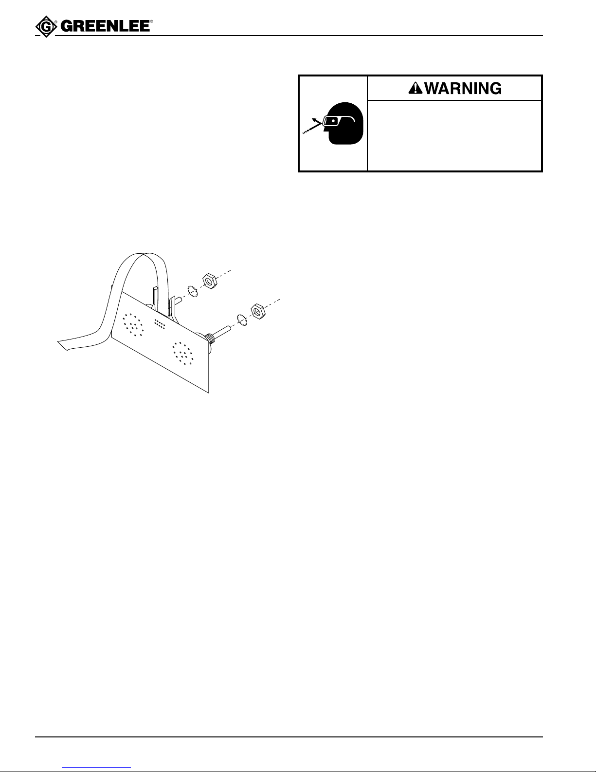
All the parts needed to upgrade the toggle switch are
included in this kit:
500 8151.9 Selector Switch
To
I/O
Note: Washer and nut included with selector switch
assembly.
Installation Instructions
Wear eye protection when performing this procedure.
Failure to wear eye protection can
result in serious eye injury from
flying debris.
Required Tools
5/16" socket wrench
Slot screwdriver with narrow tip (3/32")
9/16" open-ended wrench
1/2" open-ended wrench
.156∅ metal drill bit
Hand drill
Procedure
1. Turn off and unplug the tool.
2. Remove the top rounded shroud by removing four
5/16" hex head sheet metal screws.
3. Unplug selector switch from I/O board.
4. Use screwdriver to loosen setscrew in selector
switch knob. Remove knob. Keep knobs.
5. Use 9/16" wrench to remove nut on shaft of selector
switch. Remove and discard switch assembly.
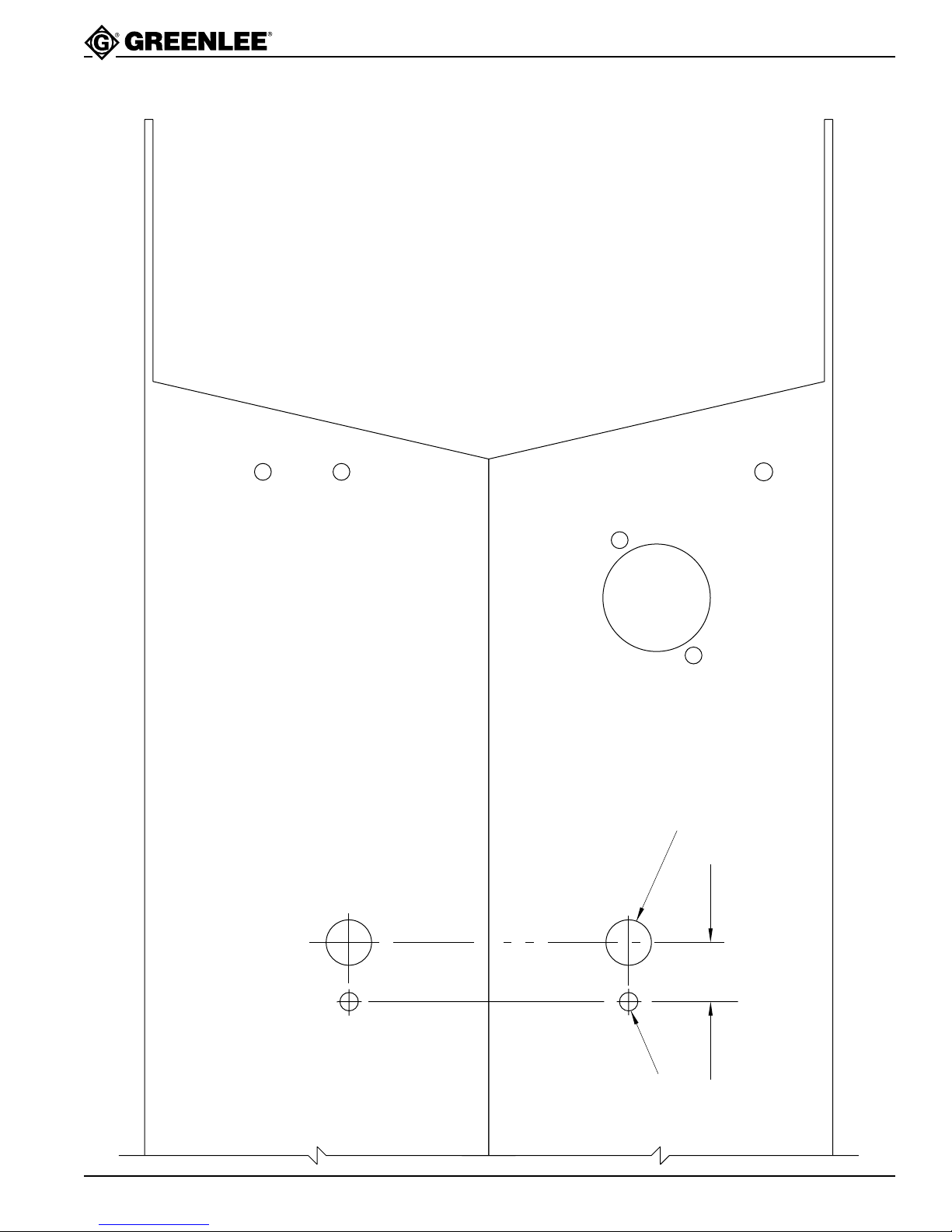
6. Using the template provided, mark location and drill
.156∅ hole. Be sure that this small hole is below the
.406∅ mounting hole so that the switch will give the
proper bend and unload directions.
7. Connect direction switch to I/O board.
8. Inside bender, insert direction switch through hole.
9. On the outside, stack the lock washer and nut onto
each switch’s mounting shaft.
10. Tighten the nuts with 1/2" wrench.
11. Replace knobs. Use screwdriver to tighten setscrew
in each selector switch knob. Be sure to align
setscrew with flat on shaft so that the switch position will line up with decal markings.
12. Replace top rounded shroud and hand-tighten four
5/16" hex head sheet metal screws.
Greenlee Textron / Subsidiary of Textron Inc.
2
4455 Boeing Dr., Rockford, IL 61109-2988 815/397-7070
Page 3
501 0299.0 Selector Switch Upgrade Kit
Template for Drilling Anti-Rotation Holes
Greenlee Textron / Subsidiary of Textron Inc.
(Existing) .406∅ x 2 REF
.531
(New) .156∅ x 2
3
4455 Boeing Dr., Rockford, IL 61109-2988 815/397-7070
Page 4

Greenlee Textron / Subsidiary of Textron Inc.
4455 Boeing Drive, Rockford, IL 61109-2988 USA
Customer Service (International): 815/397-7070 • Fax: 815/397-9247
Customer Service (North America): 800/435-0786 • Fax: 800/451-2632, 815/397-1865
Canada Fax: 800/524-2853
Printed in the U.S.A.
 Loading...