

Page 1
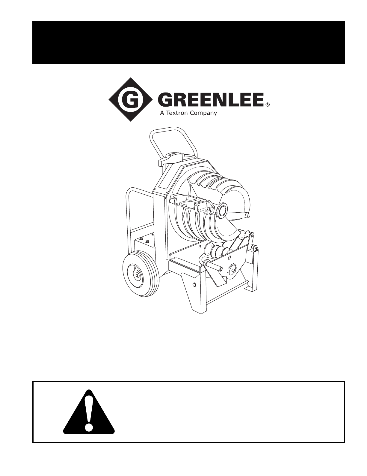
SERVICE MANUAL
Quad Bender
999 3877.4 © 2005 Greenlee Textron Inc. SB 285 REV 2 2/05
853
™
Read and understand all of the instructions and
safety information in this manual before operating
or servicing this tool.
Page 2

853 Quad Bender™
Table of Contents
Safety .............................................................................2
Purpose .......................................................................... 2
Other Publications .......................................................... 2
Important Safety Information ....................................... 3-4
Handle Removal and Replacement ............................... 5
Transporting the Bender ................................................ 5
Maintenance................................................................6-8
Troubleshooting ........................................................ 9-11
Exploded Views and Parts List................................12-19
Electrical Control Layout .............................................. 20
I/O Electrical Schematic ..........................................21-22
PCB Layout ..................................................................23
Power Generation Unit ............................................ 24-27
Purpose
This manual is intended to familiarize all personnel
with the safe service procedures for the following
Greenlee tools:
853 Quad Bender
(beginning with Serial Number ADW0000)
Keep this manual available to all personnel.
Replacement manuals are available upon request
at no charge.
The Greenlee 853 Quad Bender is protected by
U.S. Patent No. 5,226,305.
Other Publications
Instruction Manual: Publication 999 3876.6 (IM 1527)
Safety
Safety is essential in the use and maintenance of
Greenlee tools and equipment. This instruction manual
and any markings on the tool provide information for
avoiding hazards and unsafe practices related to the
use of this tool. Observe all of the safety information
provided.
Greenlee / A Textron Company 2 4455 Boeing Dr. • Rockford, IL 61109-2988 USA • 815-397-7070
Page 3
IMPORTANT SAFETY INFORMATION
SAFETY
ALERT
SYMBOL
This symbol is used to call your attention to hazards
or unsafe practices which could result in an injury
or property damage. The signal word, defined below,
indicates the severity of the hazard. The message
after the signal word provides information for preventing or avoiding the hazard.
Immediate hazards which, if not avoided, WILL result
in severe injury or death.
853 Quad Bender™
Electric shock hazard:
• Connect the power cord to a 120
volt, 20 amp receptacle on a
ground fault protected circuit only.
See Grounding Instructions.
• Do not modify the power cord or
plug.
• Inspect the power cord before use.
Repair or replace the cord if
damaged.
• Disconnect from power before
servicing.
Failure to observe this warning could
result in severe injury or death.
Hazards which, if not avoided, COULD result in severe
injury or death.
Hazards or unsafe practices which, if not avoided,
MAY result in injury or property damage.
Read and understand all of the
instructions and safety information
in this manual before operating or
servicing this tool.
Failure to observe this warning will
result in severe injury or death.
Do not use this tool in a hazardous
environment. Hazards include
flammable liquids, gases, or other
materials. Using this tool in a hazardous environment can result in a
fire or explosion.
Failure to observe this warning will
result in severe injury or death.
• Do not expose to rain.
• Do not use in wet or damp
locations.
Failure to observe these warnings
can result in severe injury or death.
Wear eye protection when operating
or servicing this tool.
Failure to wear eye protection could
result in serious eye injury from
flying debris.
Do not remove guards.
Failure to observe this warning could
result in severe injury or death.
Greenlee / A Textron Company 3 4455 Boeing Dr. • Rockford, IL 61109-2988 USA • 815-397-7070
Page 4
853 Quad Bender™
IMPORTANT SAFETY INFORMATION
Extension cords:
• Use only three-wire, 12-gauge
extension cords that have threeprong grounding-type plugs and
three-hole receptacles that accept
the tool’s plug.
• Do not use extension cords that
are longer than 30 m (100').
• Repair or replace damaged
extension cords.
Failure to observe these warnings
can result in severe injury or death.
Make sure that the handle is properly installed and
secured with the safety spring clips and snap pins
before lifting or moving the bender. An improperly
installed handle could allow the bender to fall,
injuring nearby personnel.
Failure to observe this warning can result in severe
injury or death.
• Conduit moves rapidly as it is bent. The path of
the conduit must be clear of obstructions. Be sure
clearance is adequate before starting the bend.
• Do not operate the bender while wearing loose
clothing. Loose clothing can get caught in moving
parts.
• Inspect the bender before use. Replace worn,
damaged or missing parts with Greenlee replacement parts. A damaged or improperly assembled
component could break and strike nearby personnel.
• Some bender parts and accessories are heavy
and may require more than one person to lift and
assemble.
• Use this tool for the manufacturer’s intended
purpose only. Use other than that which is
instructed in this manual can result in injury or
property damage.
Failure to observe these precautions can result in
injury or property damage.
Pinch points:
Keep hands away from bending
shoe, rollers and conduit when
bender is in use.
Unplug the bender before changing accessories.
Accidental startup can result in serious injury.
Greenlee / A Textron Company 4 4455 Boeing Dr. • Rockford, IL 61109-2988 USA • 815-397-7070
Page 5
853 Quad Bender™
Handle Removal and Replacement
The handle of the 853 is removable. This feature is
convenient when performing complex bending, and
makes it easy to replace a damaged handle.
Removal
1. Place the bender in the upright position.
2. Release the spring clip on the safety snap pin.
3. Remove the pin from the handle and the sleeve of
the frame.
4. Repeat for the other end of the handle.
5. Lift the handle to remove.
Replacement
1. Insert the handle into the sleeves of the frame.
2. Align the holes in the handle with the holes in the
sleeves.
3. Insert the safety snap pin. Ensure that the pin goes
through the handle and the sleeve on the frame.
4. Engage the safety spring clip over the end of the pin.
Ensure that the loop on the clip is completely around
the pin.
5. Repeat for the other end of the handle.
Transporting the Bender
Make sure that all components used to lift this bender
are properly rated for the 202 kg (445 lb) weight. Use
a ramp to load and unload the bender from a truck or
other vehicle that is not equipped with a lift gate.
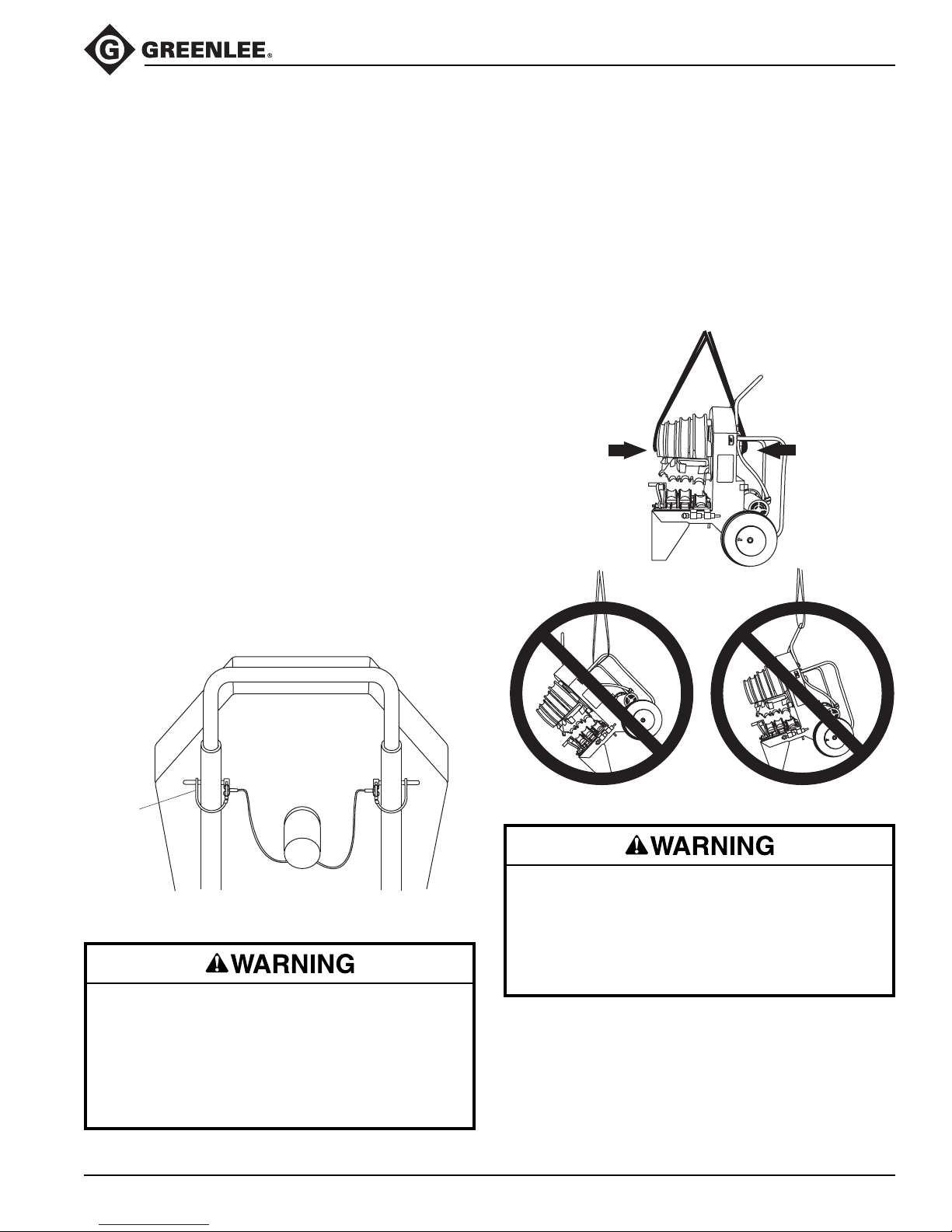
To lift the bender, loop a nylon or polyester sling through
the spindle. Thread one end of the sling through the
length of the spindle as shown. Securely fasten to lifting
device.
Lifting Bender
Removing or Replacing Handle
safety
snap
pin
Make sure that the handle is properly installed and
secured with the safety spring clips and snap pins
before lifting or moving the bender. An improperly
installed handle could allow the bender to fall,
injuring nearby personnel.
Failure to observe this warning can result in severe
injury or death.
Lift bender using a nylon or polyester sling through
the spindle. Do not attempt to lift bender by the
handles. Make sure all lifting components are
properly rated for the 202 (445 lb) weight.
Failure to observe this warning can result in severe
injury or death.
Greenlee / A Textron Company 5 4455 Boeing Dr. • Rockford, IL 61109-2988 USA • 815-397-7070
Page 6
Maintenance
There is no need for periodic flushing and replacing of
lube in the bender gear box since it is sealed and locked
tight. However, if the box is opened for repair and the
lube is lost or contaminated by dirt, then the box and
parts should be flushed out and filled with 26 fluid
ounces of Mobil® 634 synthetic oil.
Flushing should be accomplished with kerosene, which
is a petroleum hydrocarbon that does not affect seals.
Note: Aromatic hydrocarbons such as benzine,
chlorinated solvents such as carbon-tetrachloride, and
ketones such as acetone should never be used for
flushing as they are solvents for rubber. They are also
harmful to the environment.
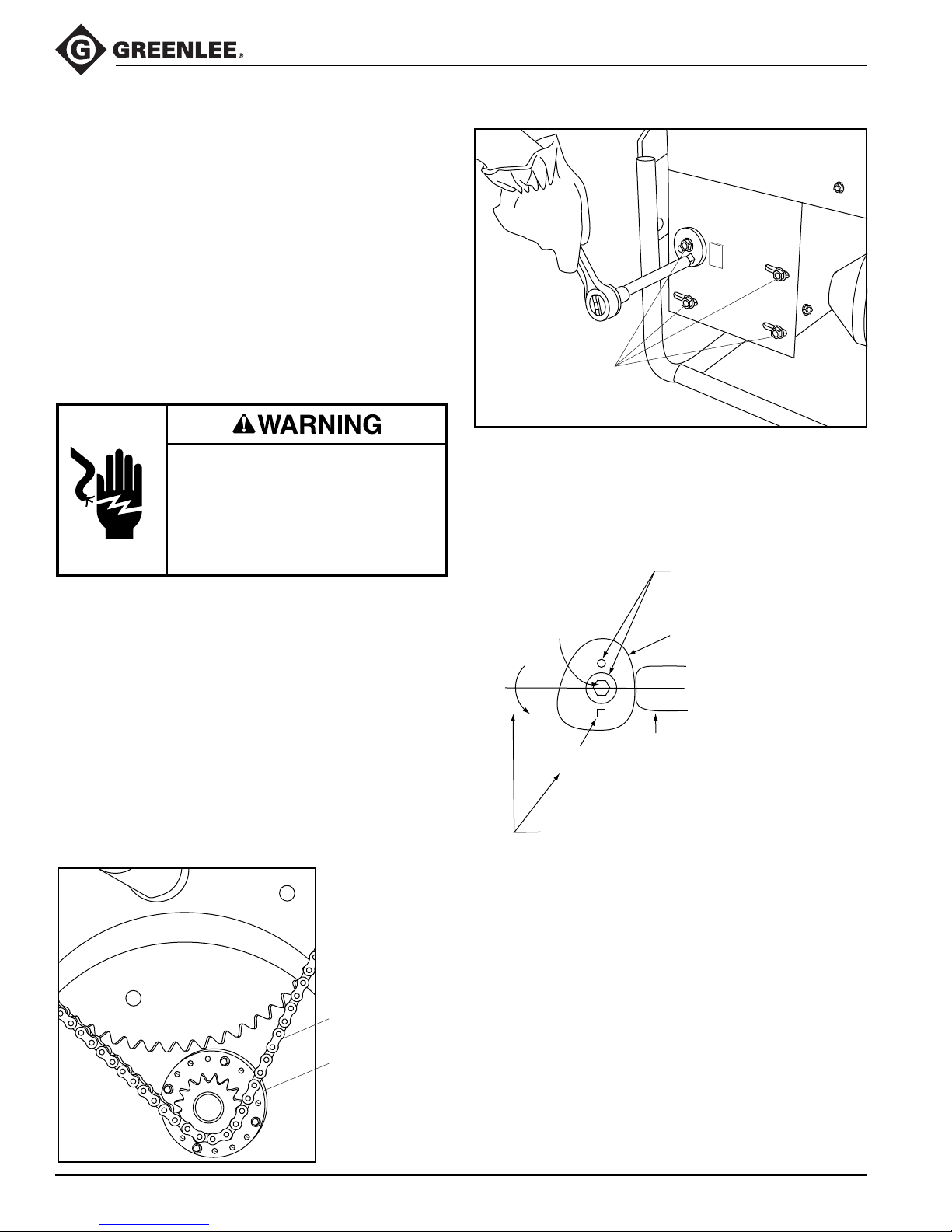
Chain Adjustment
853 Quad Bender™
Eight Reductor
Mounting Bolts
(four on reverse side)
Disconnect this tool when not in use,
before servicing or adjusting, and
when changing shoes or conduit
rollers and supports.
Failure to observe this warning could
result in severe injury or death.
Both chains have to be adjusted if the final drive #60 chain
is to be reset. Refer to the Exploded View and Parts List.
1.
Remove the front cover (38) and upper rear guard (37).
2. Loosen the eight mounting bolts for the reductor (19).
Remove the eccentric cam and move the reductor to
create chain slack.
3. Remove the four retaining screws for eccentric
adjustment. Rotate to remove slack from the chain
and align with one of the two sets of holes in the
frame. Remount the eccentric with the four bolts.
4. Slide the reductor in slotted mounting holes to the
retension chain. Set tension with the eccentric cam.
With the eight reductor mounting bolts (22, 24) loose,
rotate the eccentric cam with a 1/2" square drive to
tension the chain. Torque the eight reductor mounting
bolts to 47 Newton-meters (35 ft-lb).
Two eccentric cam mounting
holes provided for varying
Reductor
Mounting Bolt
1/2" Square
Rotate eccentric cam counterclockwise.
Apply 20 Newton-meters (15 foot-pounds) of torque
to set chain tension. Then torque reductor mounting
bolts to 47 Newton-meters (35 foot-pounds).
adjustment positions.
Eccentric Cam
Tab on
Reductor Bracket
Greenlee / A Textron Company 6 4455 Boeing Dr. • Rockford, IL 61109-2988 USA • 815-397-7070
#60 HT Final
Drive Chain
Positioning Plate on
Eccentric Housing,
Counter Shaft
Four 1/4" Flange
Mounting Screws
Page 7
Maintenance (cont’d)
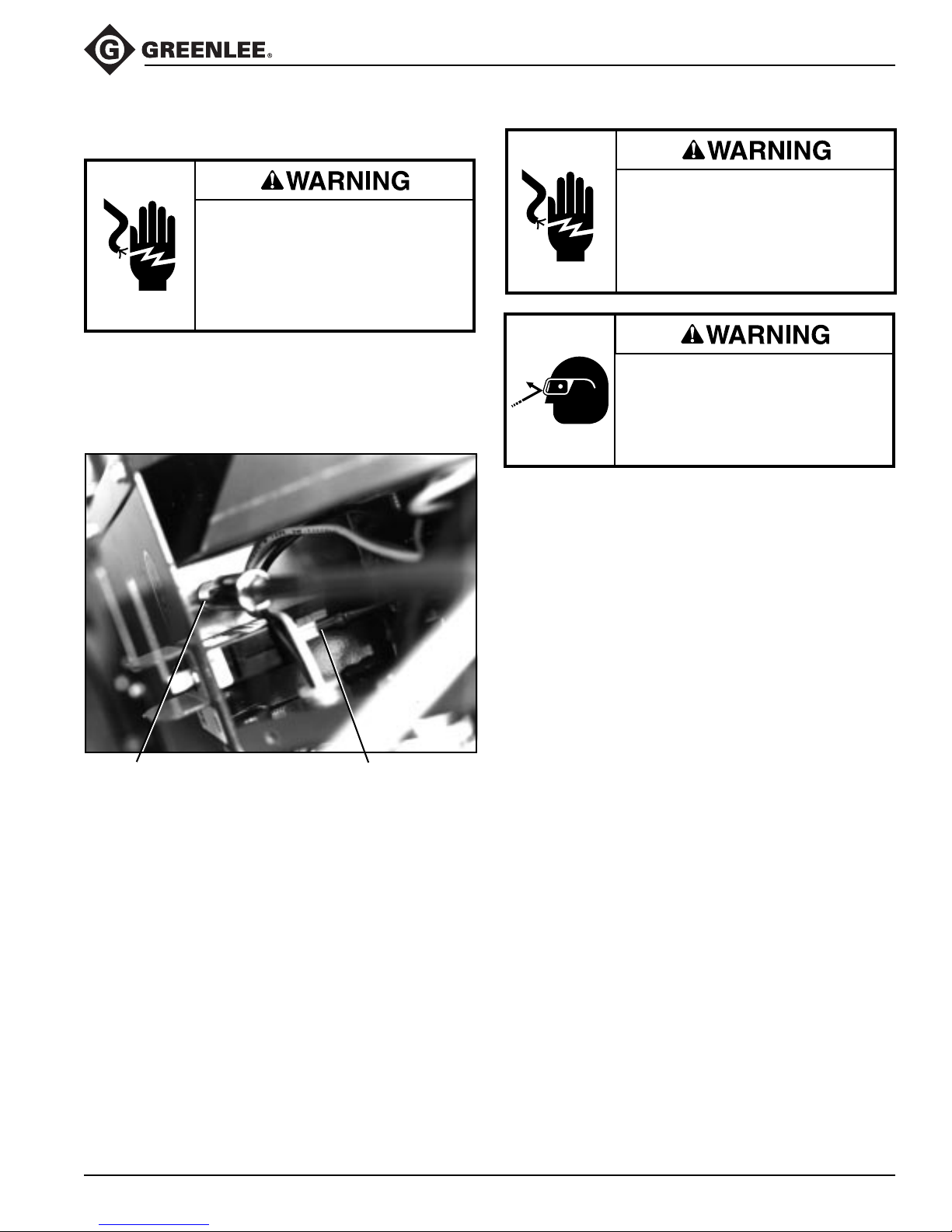
Electrical Control Unit Removal
Disconnect power supply before
servicing bender. Servicing to be
done only by trained service
technician.
Failure to observe this warning could
result in severe injury or death.
853 Quad Bender™
Electric shock hazard:
Disconnect the unit from power
before servicing.
Failure to observe this warning can
result in severe injury or death.
1. Remove the cover retained by ten 5/16" hex screws.
2. Disconnect the pendant switch plug from the circuit
board and remove through the cord grip.
3. Remove two hex mounting screws, one on each side.
3/8" Hex
Mounting Screw
4. Remove the motor leads, power cord ground wire,
and neutral wire before the control unit can be totally
removed from the bender.
Line Connection
at Circuit Breaker
Wear eye protection when operating
or servicing this tool.
Failure to wear eye protection can
result in serious eye injury from
flying debris.
Roller Support Maintenance
Clean and lubricate roller supports every 6 months, or
more often if the bender is used in dusty or corrosive
environments.
Refer to the exploded view of the bridge assembly when
performing the following procedures.
1" Roller Support
1. Disconnect the bender from the power source.
2. Remove shoulder bolt (40) and nut (41). Remove
1" arm (1).
3. Remove retaining ring (39). Remove 1" roller (5).
4. Spray a motorcycle chain or high quality axle grease
on shaft of the 1" arm (1).
5. Lubricate the shoulder bolt (40).
6. Wipe away any excess lubricant.
7. Assemble in reverse order.
Greenlee / A Textron Company 7 4455 Boeing Dr. • Rockford, IL 61109-2988 USA • 815-397-7070
Page 8
Maintenance (cont’d)
853 Quad Bender™
1-1/4" to 2" Roller Support
1. Disconnect the bender from the power source.
2. Remove the shoe and bridge assembly.
3. Place bridge on stable work surface. Use a pair of
needlenose pliers to disconnect the spring (48) from
the hole in the bridge beneath the roller support unit.
4. Remove the squeeze adjustment arm screw (38)
and arm (32).
5. Remove the three button head cap screws (37) and
adapter sleeve (33).
6. Place one hand under the support arm (2) to support
the weight of the roller support unit. Remove the
eccentric shaft (4).
Note: You may need to rotate the eccentric shaft to
remove it.
Pinch points:
Use both hands to hold the lead and
tail rollers to prevent the rollers from
pivoting.
Failure to observe this precaution
could result in injury or property
damage.
7. Lift bridge weldment (3) off of roller assembly.
8. To separate 1-1/4" and 1-1/2" roller assemblies:
Loosen the sleeve set screw (36) and remove the
1-1/4" to 1-1/2" pivot roller shaft (28). Remove the
sleeve (30).
9. On the 1-1/4" roller group:
• Remove two hex head screws (34). Remove the
outer roller plate (14).
• Remove the tail roller (7) and lead roller (6).
10. On the 1-1/2" roller group:
• Remove two hex head screws (34). Remove the
outer roller plate (14).
• Remove the tail roller (10).
• Remove all components of the split roller
assembly.
11. On the 2" roller group:
• Loosen the sleeve set screw (36) and press out
the 2" pivot shaft (29). Remove the sleeve (31).
• Remove the hex head screw (34). Remove one
retaining ring (35) from the tail roller shaft (26).
Remove outer roller plate (15).
• Remove the tail roller (9) and center roller (8).
• Remove all components of the split roller
assembly.
12. Clean off all of the grease and dirt.
13. Inspect each item. Replace any worn, damaged,
or missing items.
14. Lubricate all working surfaces with a high-quality
grease.
15. Replace all components in reverse order, noting the
following:
• On split roller groups: To ease the assembly of
the split roller subassemblies, begin by slipping
the O-rings onto the side plates. Assemble the
split roller subassemblies as shown, then slip the
O-rings into their correct positions.
• On the 2" roller group only: After replacing any
split roller components, add or remove shim
washers (42, 43, or 44) as needed.
• On the 1-1/2" roller group: Install the two Belleville
washers (21) so that the inside diameters contact
each other.
• Use Loctite® 271 on the hex head screws (34).
Torque to 55 to 61 Nm (40 to 45 ft-lb).
16. Position the roller support arm (2) as shown.
Assemble the roller groups to the support arm.
17. Place the bridge weldment (3) over roller assembly.
18. Insert the eccentric shaft (4).
Note: You may need to rotate the eccentric shaft to
get it to seat completely.
19. Install the adapter sleeve (33) and three button head
cap screws (37).
20. Install the adjustment arm (32) and adjustment arm
screw (38).
21. Attach the spring (48) to the holes in the bridge
beneath the roller support unit.
Greenlee / A Textron Company 8 4455 Boeing Dr. • Rockford, IL 61109-2988 USA • 815-397-7070
Page 9
853 Quad Bender™
Troubleshooting
Problem Probable Cause Possible Remedy
Bender will not operate. No voltage. Check supply voltage circuit operation.
Check that switch is on.
Bends are overbent a few Pointer is adjusted wrong. Loosen pointer locking screws and
degrees. rotate clockwise to compensate.
Retighten locking screws.
Too much squeeze on 1-1/4", 1-1/2" Back squeeze off per adjustment
or 2" EMT, IMC or Rigid Aluminum instructions.
conduit.
Unusual conduit characteristics. Bend smaller angle to compensate.
Bends are underbent a few Pointer is adjusted wrong. Loosen pointer locking screws and
degrees. rotate counterclockwise to compen-
sate. Retighten locking screws.
Too little squeeze on 1-1/4", 1-1/2" Increase squeeze per adjustment
or 2" EMT, IMC or Rigid Aluminum instructions.
conduit.
Unusual conduit characteristics. Bend larger angle to compensate.
Bender stops bending. Current overload. Rigid conduit is being bent with roller
support engaged. Retract roller
assembly. Conduit is bent past 105°
and hook has contacted unbent conduit.
Press UNLOAD and remove overbent
conduit.
Greenlee / A Textron Company 9 4455 Boeing Dr. • Rockford, IL 61109-2988 USA • 815-397-7070
Page 10
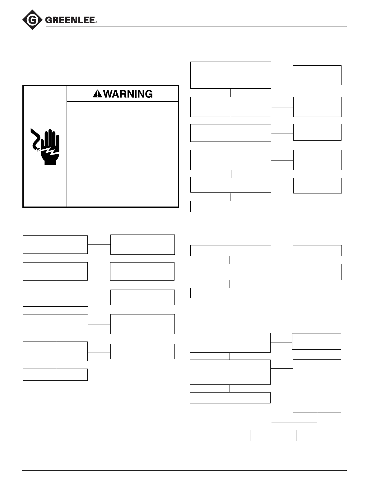
Troubleshooting (cont’d)
853 Quad Bender™
The following flow charts show the suggested troubleshooting procedures for some bender problems. They by
no means encompass all possible problems or solutions.
Electric shock hazard:
• Contact with live circuits can result
in severe injury or death.
• Some troubleshooting steps
require power to the bender.
This type of troubleshooting step
should only be performed at
authorized Greenlee service
centers by personnel who are
familiar with safe troubleshooting
procedures.
Failure to observe these warnings
could result in severe injury or death.
Won’t bend
Plugged into dead circuit,
Is 115 VAC measured at
PGU BOARD input?
YES
Does the green LED on
the I/O BOARD light?
YES
Does the green LED on
the PGU light?
YES
Does amber or red LED
on IO light when BEND
or UNLOAD is pressed?
YES
Does relay on IO
operate when BEND or
UNLOAD is pressed?
YES
Replace PGU.
NO
bad power cord, or
switch is bad or off.
NO
Replace transformer unit.
NO
Replace PGU.
Unplug pendant or IO and
NO
check switch for continuity.
If ok, replace IO.
NO
Replace IO.
Trips circuit breaker
Are the proper support rollers
and shoe groove being used for
the type and size of conduit
being bent?
YES
Is the current on the 115 VAC
line exceeding 20 amps?
YES
Is the DC current to the motor
exceeding 17 amps?
NO
When BEND is pressed, is the
voltage sent to the motor 20 to 50
volts over the AC line voltage?
YES
Are connectors corroded?
NO
Replace PGU.
NO
NO
YES
NO
YES
Won’t stop
Is the supply line voltage low?
NO
Does bender stop when the
pendant is unplugged?
NO
Replace PGU.
YES
YES
Bender only runs in one direction
Does amber or red LED light
when switch is pressed?
YES
When amber or red LED is on, is
12 VDC measured at large relay
coil on PGU (where relay wire
unit connects)?
YES
Replace 918 6645.6 relay.
NO
NO
Follow directions in
instruction manual.
Replace circuit
breaker.
Replace motor.
Replace
bridge rectifier
(918 5997.2).
Clean.
Use 115 VAC.
Replace pendant
switch.
Check and replace
pendant switch.
Move six-wire
connector on PGU
from “to I/O” to
“test.” Alternately
press BEND and
UNLOAD. Does
yellow “direction”
LED on PGU turn
on and off?
Greenlee / A Textron Company 10 4455 Boeing Dr. • Rockford, IL 61109-2988 USA • 815-397-7070
NOYES
Replace PGU. Replace I/O.
Page 11

Quick diagnostics for electronic problems
1. With bender unplugged, switch six-wire connector on
PGU from “To I/O” to “Test.”
2. Plug unit in.
3. Press BEND. Contactor on I/O will activate.
• If not, check for 12 VDC at contactor coil
— If 12 VDC is present, replace contactor
918 6645.6—else replace I/O
• If bender runs, replace PGU.
• On PGU near “test” connector:
Green “Power” LED is ON
Yellow “Direction” LED is OFF
Red “PWM” LED slowly turns dimly on
If not, replace I/O.
4. Press UNLOAD. Contactor on I/O will activate.
• If not, check for 12 VDC at contactor coil
— If 12 VDC is present, replace contactor
918 6645.6—else replace I/O
• On PGU near “test” connector:
Green “Power” LED is ON
Yellow “Direction” LED is ON
Red “PWM” LED slowly turns dimly on
If not, replace I/O.
5. Press BEND. With insulated object, carefully press
black button “S1” on PGU. Bender will run slowly.
If not, replace PGU.
853 Quad Bender™
Greenlee / A Textron Company 11 4455 Boeing Dr. • Rockford, IL 61109-2988 USA • 815-397-7070
Page 12
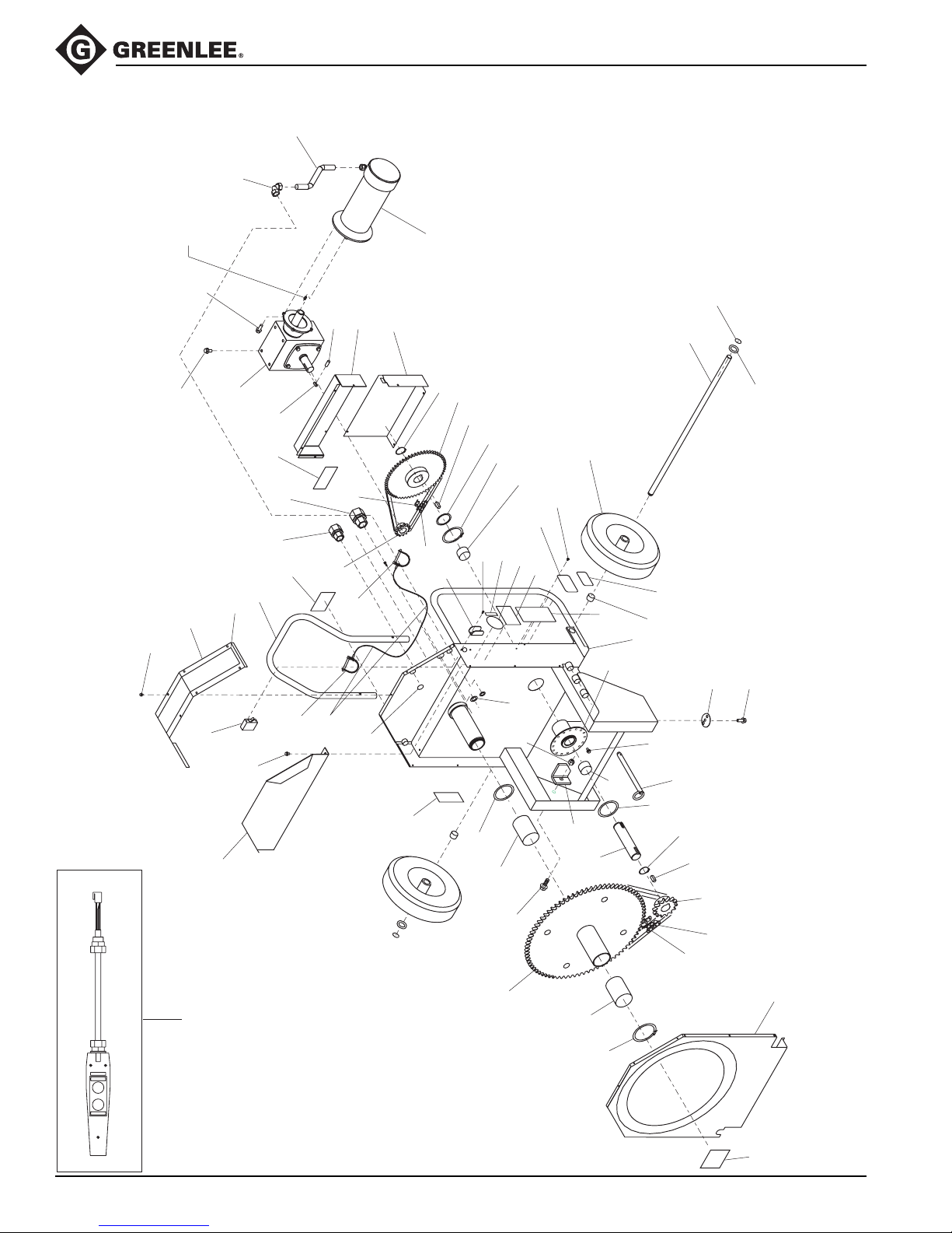
Exploded View — 853 Quad Bender
26
27
Note: Key supplied
with item #19
(reductor)
853 Quad Bender™
25
39
22
47
24
41
19
71
54
79
74
18
30
28
76
78
52
59
17
20
78
37
31
36
73
21
42
77
12
14
34
32
70
11
9
35
7
44
43
58
40
46
45
75
72
80
1
8
24
23
29
89
54
7
49
11
2
88
77
141
142
BEND
UNLOAD
Greenlee / A Textron Company 12 4455 Boeing Dr. • Rockford, IL 61109-2988 USA • 815-397-7070
5
10
14
13
24
16
15
3
38
5
6
48
Page 13

Parts List — 853 Quad Bender
Key Part No. Description Qty.
1 500 7275.7 Weldment, main frame ...................................................................... 1
2 502 3452.8 Washer, fiber ..................................................................................... 1
3 500 7277.3 Weldment, sprocket unit .................................................................... 1
5 905 2410.1 Bearing, Fiberglide ø2.625 x 3.75 long ............................................. 2
6 905 2414.4 Ring, retaining #5100-237 ................................................................. 1
7 905 2412.8 Bearing, Fiberglide ø1.625 x 1.00 long ............................................. 2
8 503 9763.0 Weldment, countershaft .................................................................... 1
9 905 4023.9 Ring, retaining #5100-250 ................................................................. 1
10 503 9764.8 Shaft, counter .................................................................................... 1
11 905 2413.6 Bearing, thrust Fiberglide .................................................................. 2
12 905 4548.6 Sprocket, #40 60T ............................................................................. 1
13 905 4253.3 Sprocket, #60 14T ............................................................................. 1
14 503 9765.6 Key, countershaft .............................................................................. 2
15 905 4546.0 Chain, #60 87P.................................................................................. 1
16 905 4251.7 Masterlink, #60 .................................................................................. 1
17 905 4547.8 Sprocket, #40 13T ............................................................................. 1
18 500 8431.3 Key, reductor sprocket ...................................................................... 1
19 905 2388.1 Reductor, worm gear ......................................................................... 1
20 905 2787.9 Masterlink, #40 .................................................................................. 1
21 905 4551.6 Chain, #40 87P.................................................................................. 1
22 905 4568.0 Bolt, 3/8–16 UNC x .75...................................................................... 7
23 503 9758.3 Eccentric............................................................................................ 1
24 905 4237.1 Bolt, 3/8–16 UNC x 1.00.................................................................... 6
25 918 6973.0 Motor ................................................................................................. 1
26 905 4549.4 Conduit, Sealtight .............................................................................. 1
27 918 5214.5 Elbow, Sealtight................................................................................. 1
28 918 6683.9 Strain relief ........................................................................................ 1
29 905 1170.0 Nut, 3/4 conduit lock .......................................................................... 1
31 918 6263.9 Nut, 1/2 conduit lock .......................................................................... 1
32 503 9757.5 Axle ................................................................................................... 1
34 905 1528.5 Ring, retaining #5160-75 ................................................................... 2
35 905 5267.9 Wheel, urethane-filled ....................................................................... 2
36 503 9768.0 Guard, rear lower .............................................................................. 1
37 503 9769.9 Guard, rear upper .............................................................................. 1
38 503 9760.5 Cover, front........................................................................................ 1
39 905 1655.9 Screw, #10–16 x .50 hex head ........................................................ 31
40 905 0430.5 Screw, #6–32 x .375 Phillips ............................................................. 2
41 918 6385.6 Switch, air pax ................................................................................... 1
42 502 9708.2 Guard, switch .................................................................................... 1
43 500 7920.4 Nameplate ......................................................................................... 1
44 905 3001.2 Rivet, pop 1/8 x 1/8 drive................................................................... 4
45 500 7248.6 Decal, voltage.................................................................................... 1
46 503 0392.9 Decal, damp warning......................................................................... 1
47 503 9759.1 Cover, top .......................................................................................... 1
48 503 5191.5 Decal, safety...................................................................................... 1
853 Quad Bender™
Greenlee / A Textron Company 13 4455 Boeing Dr. • Rockford, IL 61109-2988 USA • 815-397-7070
Page 14

Parts List — 853 Quad Bender (cont’d)
Key Part No. Description Qty.
49 905 3389.5 Pin, hitch............................................................................................ 1
52 905 4552.4 Lanyard ............................................................................................. 2
54 905 4335.1 Screw, 1/4 x .37 thread-forming ........................................................ 6
58 503 8974.2 Decal, circuit breaker......................................................................... 1
59 905 5323.3 Pin, Driv-Lok, 1/8 x 1/2 ...................................................................... 1
70 905 1740.7 Washer, flat ....................................................................................... 2
71 500 7935.2 Decal, instruction ............................................................................... 1
72 503 9918.7 Decal, warning (English) ................................................................... 1
73 500 0112.4 Decal, warning (French) .................................................................... 1
74 500 8380.5 Decal, proper Lifting .......................................................................... 1
75 500 3141.4 Decal, FCC Part 15 ........................................................................... 1
76 999 3576.7 Decal, technical assistance ............................................................... 1
77 905 1051.8 Ring, retaining #5100-150 ................................................................. 2
78 905 5268.7 Pin, safety snap ................................................................................. 2
79 503 9748.6 Handle, upper .................................................................................... 1
80 500 6919.5 Sleeve, axle ....................................................................................... 2
88 500 8189.6 Bracket, locator ................................................................................. 1
89 905 2646.5 Nut, 3/8" - 16 ..................................................................................... 1
853 Quad Bender™
141 500 7869.0 Electronic control assembly (fully assembled) .................................. 1
141A 500 7871.2 I/O control assembly..................................................................... 1
141B 500 8357.0 Power generation unit................................................................... 1
141C 500 7867.4 Bracket, electronics (metal bracket only)...................................... 1
142 500 7887.9 Pendant control assembly ................................................................. 1
143 500 7912.3 Power cord assembly ........................................................................ 1
Greenlee / A Textron Company 14 4455 Boeing Dr. • Rockford, IL 61109-2988 USA • 815-397-7070
Page 15
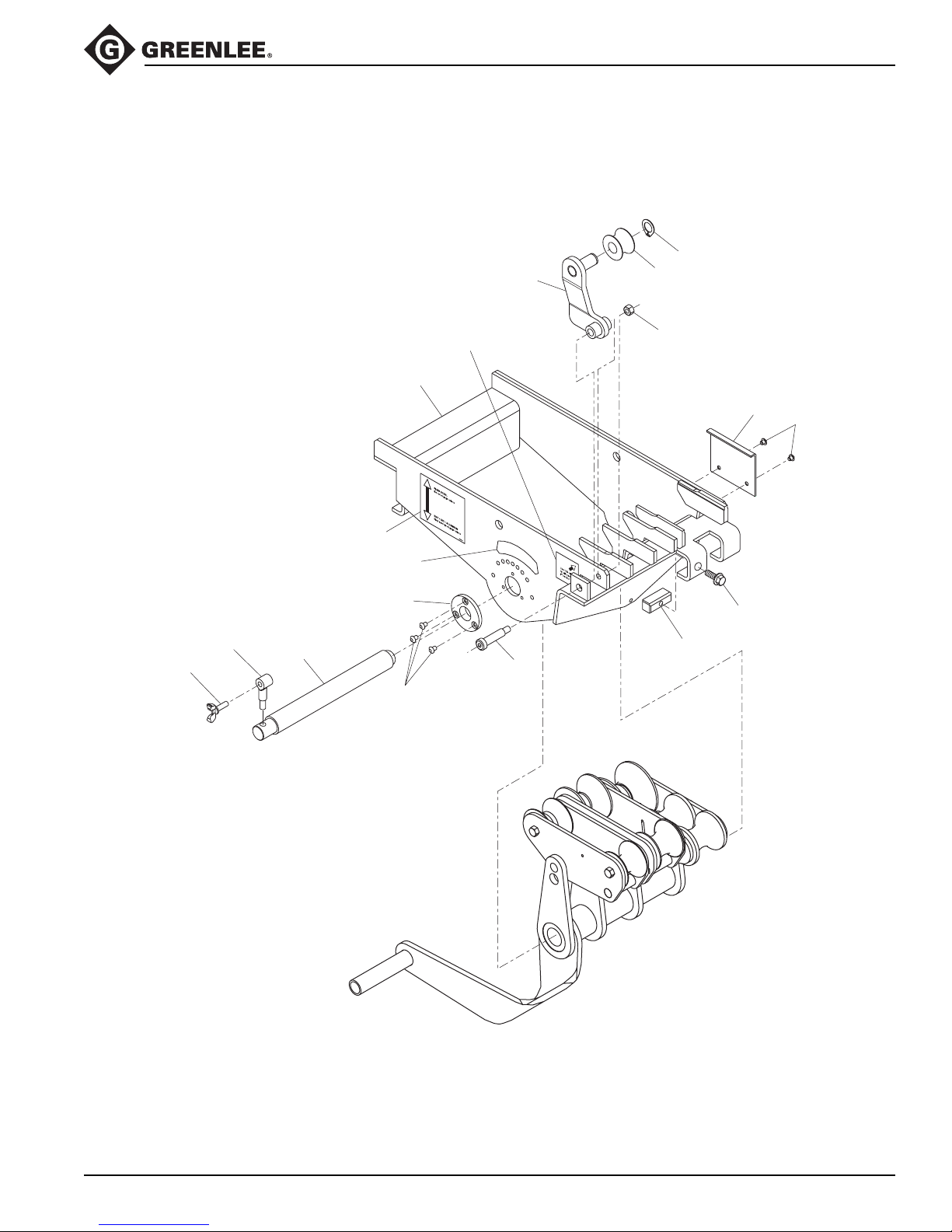
Exploded View—500 7276.6 Bridge Assembly
1
853 Quad Bender™
39
5
38
32
51
3
50
49
33
4
40
37
41
52
53
45
46
Greenlee / A Textron Company 15 4455 Boeing Dr. • Rockford, IL 61109-2988 USA • 815-397-7070
Page 16
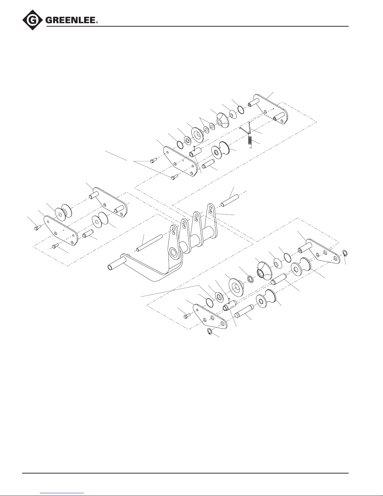
Exploded View—500 7276.6 Bridge Assembly (cont’d)
22
17
16
21
22
17
16
30
36
10
25
29
2
34
14
For all #34 screws:
apply a high-strength
thread-locking agent such as
Loctite 271 to the threads
and then tighten to 45 ft-lb.
34
11
6
14
853 Quad Bender™
12
47
48
7
24
34
Use slim washers #42, #43, #44
between the 2" ball (#19) and
outer plate (#15) to allow free
movement of the split roller
with no more than 1/32: axial
free play.
28
34
15
23
19
36
35
18
31
20
13
23
19
18
35
9
27
8
26
Greenlee / A Textron Company 16 4455 Boeing Dr. • Rockford, IL 61109-2988 USA • 815-397-7070
Page 17

Parts List—500 7276.6 Bridge Assembly
Key Part No. Description Qty.
1 500 7239.0 1" Arm weldment ............................................................................... 1
2 500 7247.1 Arm weldment ................................................................................... 1
3 500 7284.6 Bridge weldment................................................................................ 1
4 500 7258.7 Shaft eccentric................................................................................... 1
5 500 7259.5 Roller, 1" ............................................................................................ 1
6 500 7261.7 Roller, 1-1/4" lead .............................................................................. 1
7 500 7262.5 Roller, 1-1/4" tail ................................................................................ 1
8 500 0559.5 Roller unit, 2" ..................................................................................... 1
9 503 8253.5 Roller, 2" tail ...................................................................................... 1
10 503 8252.7 Roller, 1-1/2" IMC .............................................................................. 1
11 500 7264.1 Support weldment, 1-1/4" .................................................................. 1
12 500 0528.6 Support weldment, 1-1/2" .................................................................. 1
13 500 0601.0 Support weldment, 2" ........................................................................ 1
14 500 0543.0 Plate, 1-1/2" outer roller .................................................................... 2
15 500 0604.5 Plate, 2" outer roller ........................................................................... 1
16 503 8254.3 Rol, 1-1/2" ......................................................................................... 2
17 503 8264.0 Ball, 1-1/2" ......................................................................................... 2
18 503 8255.1 Rol, 2" ................................................................................................ 2
19 503 8263.2 Ball, 2" ............................................................................................... 2
20 503 8262.4 Spacer, 2" roller ................................................................................. 1
21 905 4248.7 Washer, Belleville 1.362 x .803 ......................................................... 2
22 905 1130.1 O-ring, 1.50 x 1.62 x .062 .................................................................. 2
23 905 1537.4 O-ring, 1.75 x 1.87 x .062 .................................................................. 2
24 500 7266.8 Shaft,1-1/4" support .......................................................................... 1
25 500 0860.9 Shaft, 1-1/2" support ......................................................................... 1
26 500 0493.0 Shaft, 2" rear roller ............................................................................ 1
27 503 8657.3 Shaft, 2" middle roller ........................................................................ 1
28 500 7265.0 Shaft, 1-1/2" pivot roller ..................................................................... 1
29 503 1728.8 Shaft, 2" pivot .................................................................................... 1
30 503 2027.0 Sleeve, 1-1/2" .................................................................................... 1
31 503 8151.2 Sleeve, 2" .......................................................................................... 1
32 503 8225.0 Arm, adjustment ................................................................................ 1
33 503 8251.9 Sleeve, adapter ................................................................................. 1
34 905 0540.9 Screw, 7/16-14 x 1.00 hex head ....................................................... 5
35 905 4819.1 Retaining ring, #5100-87 ................................................................... 2
36 905 0881.5 Screw, 1/4-28 x .25 set...................................................................... 2
37 905 4242.8 Screw, 1/4-20 x .38 button head ....................................................... 3
38 905 5282.2 Screw, 5/18 wing ............................................................................... 1
39 905 0283.3 Retaining ring, #5100-75 ................................................................... 1
40 905 5293.8 Shoulder bolt, 1/2" x 2.00 .................................................................. 1
41 905 0639.1 Nut, 3/8-16 hex .................................................................................. 1
42 905 3918.4 Washer, 1.00 x 1.37 x .030 shim ....................................................... 1
43 905 2644.9 Washer, 1/32 shim ............................................................................ 1
44 905 2645.7 Washer, 1/16 shim ............................................................................ 1
45 500 7464.4 Flip Stop ............................................................................................ 1
46 905 5303.9 Screw, 1/4-20 x .25 button head ....................................................... 2
47 503 8592.5 Guide, spring ..................................................................................... 1
48 905 4243.6 Spring, extension............................................................................... 1
49 503 8899.1 Decal, roller adjustment..................................................................... 1
50 500 7921.2 Decal, roller engagement .................................................................. 1
51 500 7936.0 Decal, 1" roller ................................................................................... 1
52 500 8190.0 Block, locator ..................................................................................... 1
53 905 4237.1 Screw, 3/8-16 x 1.00 hex .................................................................. 1
853 Quad Bender™
Greenlee / A Textron Company 17 4455 Boeing Dr. • Rockford, IL 61109-2988 USA • 815-397-7070
Page 18
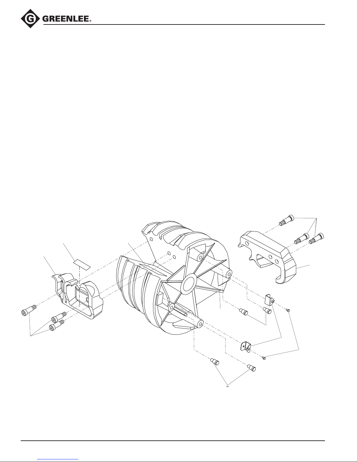
Exploded View/Parts List—500 7271.4 Shoe Assembly
Bending Shoe 1" to 2"
EMT, IMC and Rigid Conduit
Key Part No. Description Qty.
1 500 7271.4 Bending shoe assembly
(includes items 2–10) .......................... 1
2 500 7160.2 Hook, EMT ........................................... 1
3 500 7162.9 Hook, IMC/RIGID................................. 1
4 905 3396.8 Bolt ...................................................... 6
5 502 3422.6 Stud, drive ........................................... 4
6 500 7281.1 Pointer ................................................. 2
7 500 7270.6 Screw, 1/4 - 20 x .38 ........................... 2
8 500 7933.6 Decal, 1" - 2" EMT ............................... 1
9 500 7934.4 Decal, 1" - 2" IMC/RIGID ..................... 1
10 500 8381.3 Decal, shoe weight .............................. 2
853 Quad Bender™
4
NOTE: Second decal
on opposite hook in
same location
10
8
3
2
9
5
4
6
7
Greenlee / A Textron Company 18 4455 Boeing Dr. • Rockford, IL 61109-2988 USA • 815-397-7070
Page 19
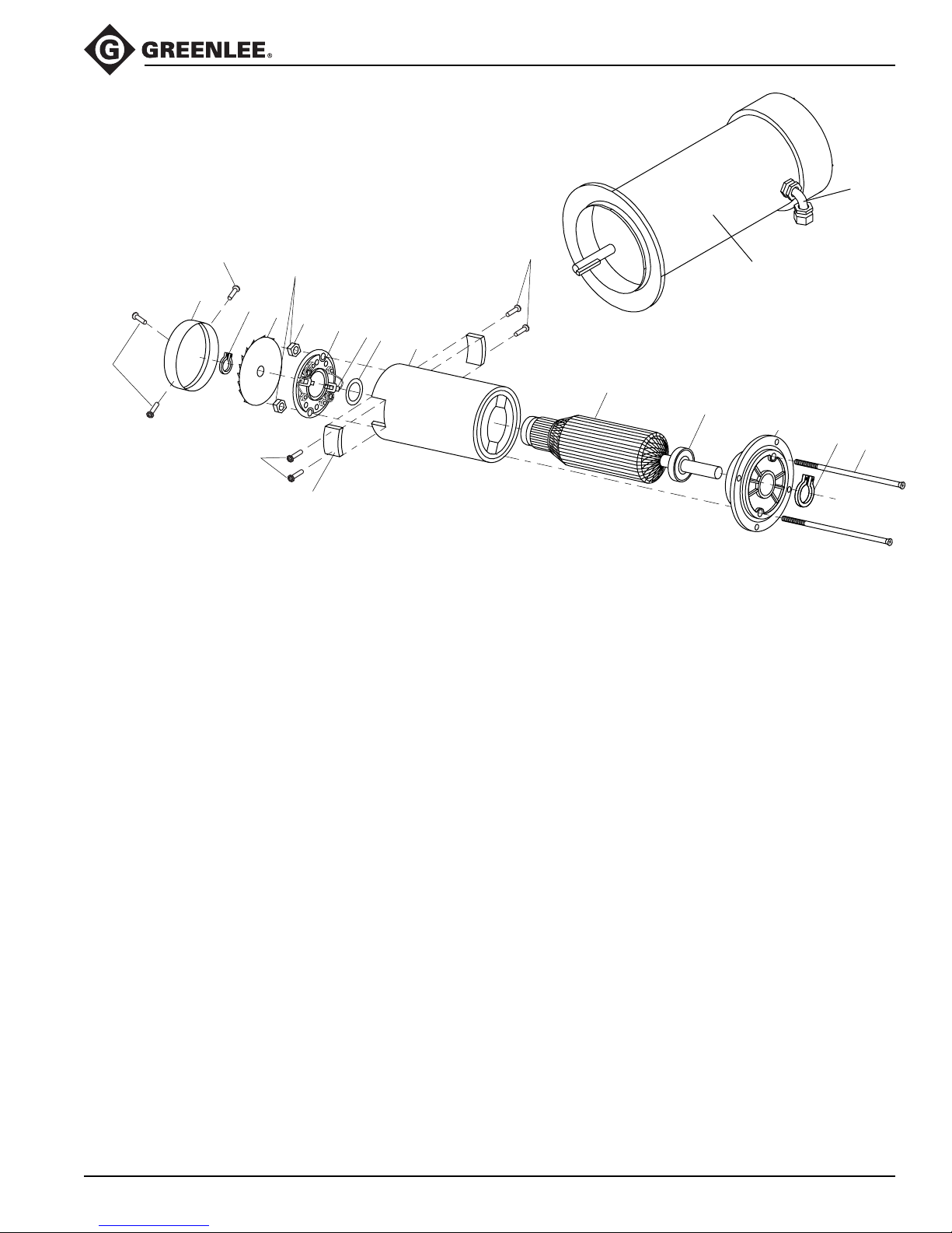
Exploded View/Parts List—115 Volt Motor
Torque to
117
102
117
9 Newton-meters
(80 inch-pounds)
103
104
117
105
116
106
107
108
109
117
110
853 Quad Bender™
115
101
111
112
113
114
Pacific Scientific
Key Part No. Description Qty.
101* 918 6417.8 Motor, 115 volt (standard) (SRF-3745-4676-2-56C) ...... 1
102 918 6471.2 Fan cover ........................................................................1
103 905 5071.4 Retaining ring.................................................................. 1
104 918 6432.1 Fan .................................................................................. 1
105 918 6428.3 End bell nut ..................................................................... 2
106 918 6419.4 Bell, rear end...................................................................1
107 918 6420.8 Brush............................................................................... 2
108 918 6422.4 Thrust washer .................................................................1
109* 918 6427.5 Shell and magnet assembly, 115V .................................1
110* 918 6425.9 Armature, 115V ............................................................... 1
111 918 6421.6 Bearing kit .......................................................................2
112 918 6418.6 Bell, front end.................................................................. 1
113 918 6424.0 Retaining ring.................................................................. 1
114 918 6426.7 Tie bolt, 115V.................................................................. 2
115 918 5876.3 90° Connector ................................................................. 1
116 918 6430.5 Brush cover ..................................................................... 2
117 918 6431.3 Cover screw .................................................................... 7
* Note: Alternate motor.
Check motor part number before ordering magnet shell or armature.
101 918 6973.0 Motor (SRF-3648-5532-7-56C)
109 918 6975.7 Shell and magnet assembly
110 918 6974.9 Armature
Greenlee / A Textron Company 19 4455 Boeing Dr. • Rockford, IL 61109-2988 USA • 815-397-7070
Page 20
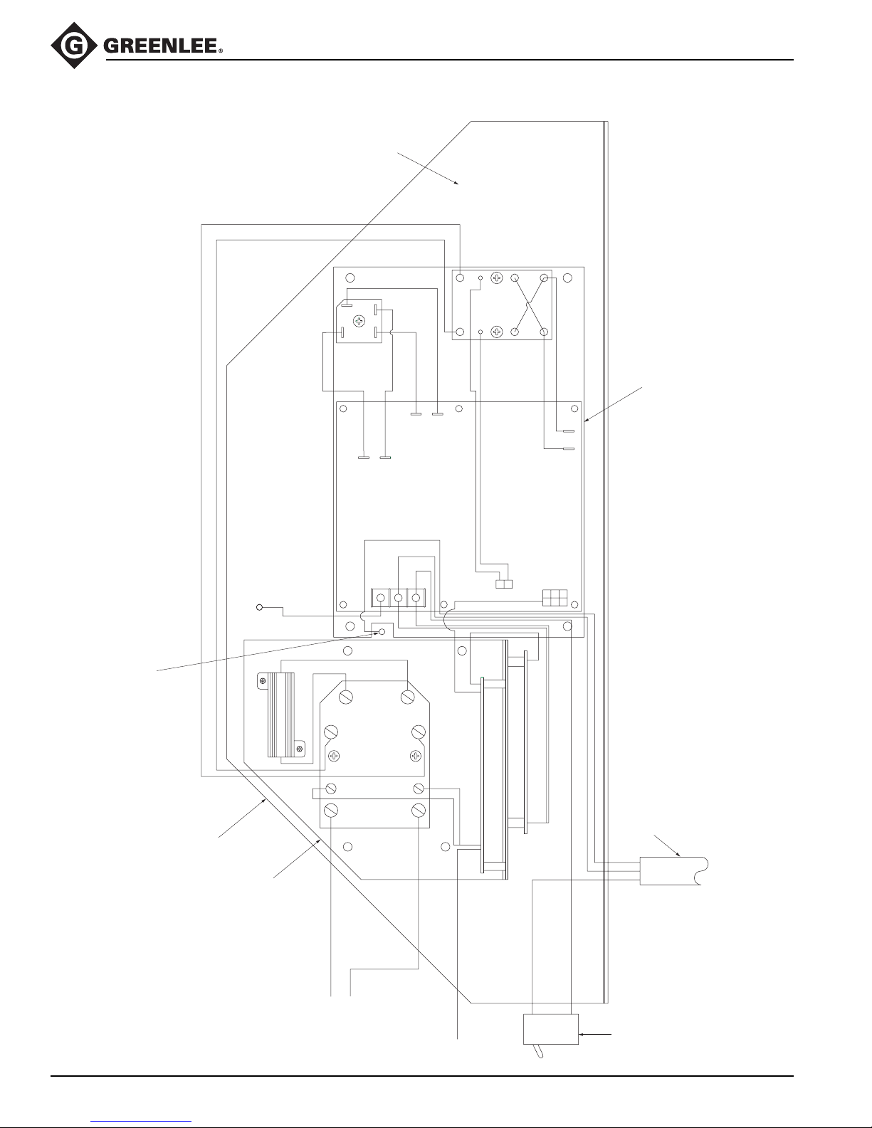
Electrical Control System Layout
853 Quad Bender™
141C
(bracket only)
141B
72, 65
141
(fully assembled)
141A
TO MOTOR (25)
WHITE
BLACK
GREEN
WHITE
BLACK
(143)
POWER CORD
GREEN
WHITE
BLACK
Greenlee / A Textron Company 20 4455 Boeing Dr. • Rockford, IL 61109-2988 USA • 815-397-7070
(142)
TO PENDANT
LINE
LOAD
41
Page 21
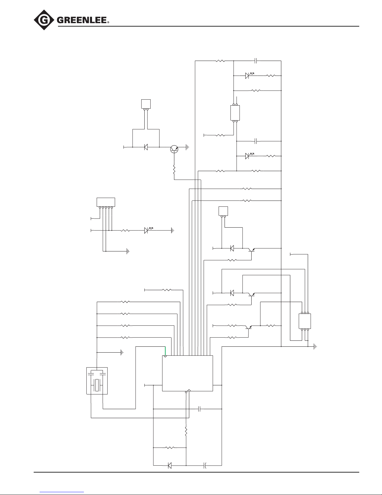
I/O Electrical Schematic (500 7871.2)
853 Quad Bender™
+5V +12V
10K
R23
2
1
JP2
D1
MECHANICAL BRAKE
Molex 39-28-1023
UF1001DI
Q1
R10
+5V
TIP122
43
21
JP4
150
+12V
10K
470
R5
JP1
54321
DC POWER IN
Molex 26-60-4050
POWER
GREEN LED
D2
330
R6
R22
JP3
1
2
RELAY COIL
Molex 39-28-1023
D5
UF-1001-DI
+12V+12V+5V
470
R14
C4
DIR B
D7
AMBER LED
10K
R18
PENDANT
Molex 39-28-1043
C3
DIR A
D6
RED LED
10K
R17
10K
R16
10K
R15
PN2222A
Q4
_RUN/BRAKE__DIRECTION_
.1uF/50V
.1uF/50V
R21
R20
330
330
Note: All resistors 5% 1/4W unless noted.
+12V
X1
4.0 MHz
10K
+5V
R7
10K
R4
10K
R3
10K
R2
10K
R1
RUN/BRAKE
DIR B
DIR A
PWM
DIRECTION
MECH BRAKE
UNUSED2
UNUSED1
18
15
2
OSC2/CLKOUT
U1
+5V
3
1
R8
D3
RA1/AN117RA0/AN0
10K
1N4148
3
2
1
RA3/AN3
RA4/TOCKI
RA2/AN2/VREF
1K
R9
6
RB0/INT
OSC1/CLKIN
MCLR
4
16
C1
13
.1uF/50V
C2
4.7uF/50V
RB712RB611RB510RB49RB38RB27RB1
PIC16C620
D4
UF-1001-DI
470
R13
150
R12
470
R11
Q3
PN2222A
Q2
PN2222A
_PWM_
R19
1K
JP5
654321
TO PGU
Molex 39-28-1063
Greenlee / A Textron Company 21 4455 Boeing Dr. • Rockford, IL 61109-2988 USA • 815-397-7070
Page 22
853 Quad Bender™
I/O Electrical Schematic (500 7871.2) Parts List
Reference Supplier Part Number Description Qty.
C1,C3,C4 Philips A104K29X7RFVVWN Capacitor, 0.1 uF, 50 volts 3
AVX SA115C104KAA
KEMET C420C104K5R5CA
C2 Panasonic ECE-A50Z4R7 Capacitor, 4.7 uF, 50 volts 1
D1,D4,D5 Diodes Inc. UF-1001-DI Diode, Ultra-Fast Switching Rectifier 3
D2 Panasonic LN38GP LED, T1, Green 1
Liteon LTL-4231
D3 Generic 1N4148 Diode 1
D6 Panasonic LN28RP LED, T1, Red 1
D7 Panasonic LN48YP LED, T1, Amber 1
JP1 Molex 26-61-4050 Connector, Locking, 0.156" cc, 5-position, Gold 1
JP4 Molex 39-29-0043 Connector, Minifit Jr., 4-position, Gold 1
JP2,JP3 Molex 39-29-0023 Connector, Minifit Jr., 2-position, Gold 2
JP5 Molex 39-29-0063 Connector, Minifit Jr., 6-position, Gold 1
Q1 Generic TIP122 Transistor, NPN 1
Q1–Heat Sink Hardware AAVID 577002B04000 Heat Sink, TO-220, .75 x .52 x .25", with Tab 1
Q2,Q3,Q4 Generic PN2222A Transistor, NPN 3
R1,R2,R3,R4,R7,R8,R15, Generic Resistor, 10K, 1/4 watt, 5% 12
R16,R17,R18,R22,R23
R5,R11,R13,R14 Generic Resistor, 470 Ω, 1/4 watt, 5% 4
R6,R20,R21 Generic Resistor, 330 Ω, 1/4 watt, 5% 3
R9,R19 Generic Resistor, 1 kΩ, 1/4 watt, 5% 2
R10,R12 Generic Resistor, 150 Ω, 1/4 watt, 5% 2
U1 Greenlee 91869382 Processor, Programmed, 854 1
X1 Murata CST4.00MGW Resonator, 4.0 Mhz 1
Liteon LTL-4221
Liteon LTL-4251
Generic #4-40 Lock Washer Stainless Steel, Split Ring or Internal Tooth 1
Generic #4-40 Hex Nut Stainless Steel 1
Generic #4-40 Phillips Screw Stainless Steel, Machine, Pan Head, #4-40 x 0.25" 1
Panasonic EFO-GC4004A4
Greenlee / A Textron Company 22 4455 Boeing Dr. • Rockford, IL 61109-2988 USA • 815-397-7070
Page 23
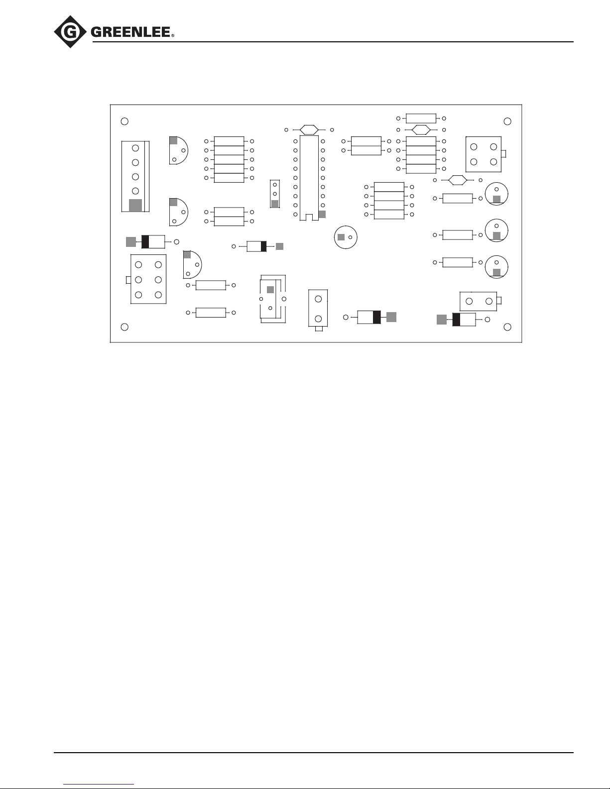
PCB Layout (500 7871.2)
853 Quad Bender™
GREENLEE TEXTRON ©2000
JP1
D4
12
JP5
456
3
TO PGU
R20
R10
C3
JP4
R17
R18
R15
12
C4
R21
R16
34
SELECTOR
DIR B
D7
DIR A
D6
POWER
R6
D2
RELAY
JP3
1
2
D5
C1
Q4
Q3
R1
R2
R5
R14
R13
R11
R8
X1
U1
D3
Q2
R12
BRAKE
Q1
R19
R22
R23
R9
R7
R4
R3
C2
+
1
JP2
2
D1
Greenlee / A Textron Company 23 4455 Boeing Dr. • Rockford, IL 61109-2988 USA • 815-397-7070
Page 24
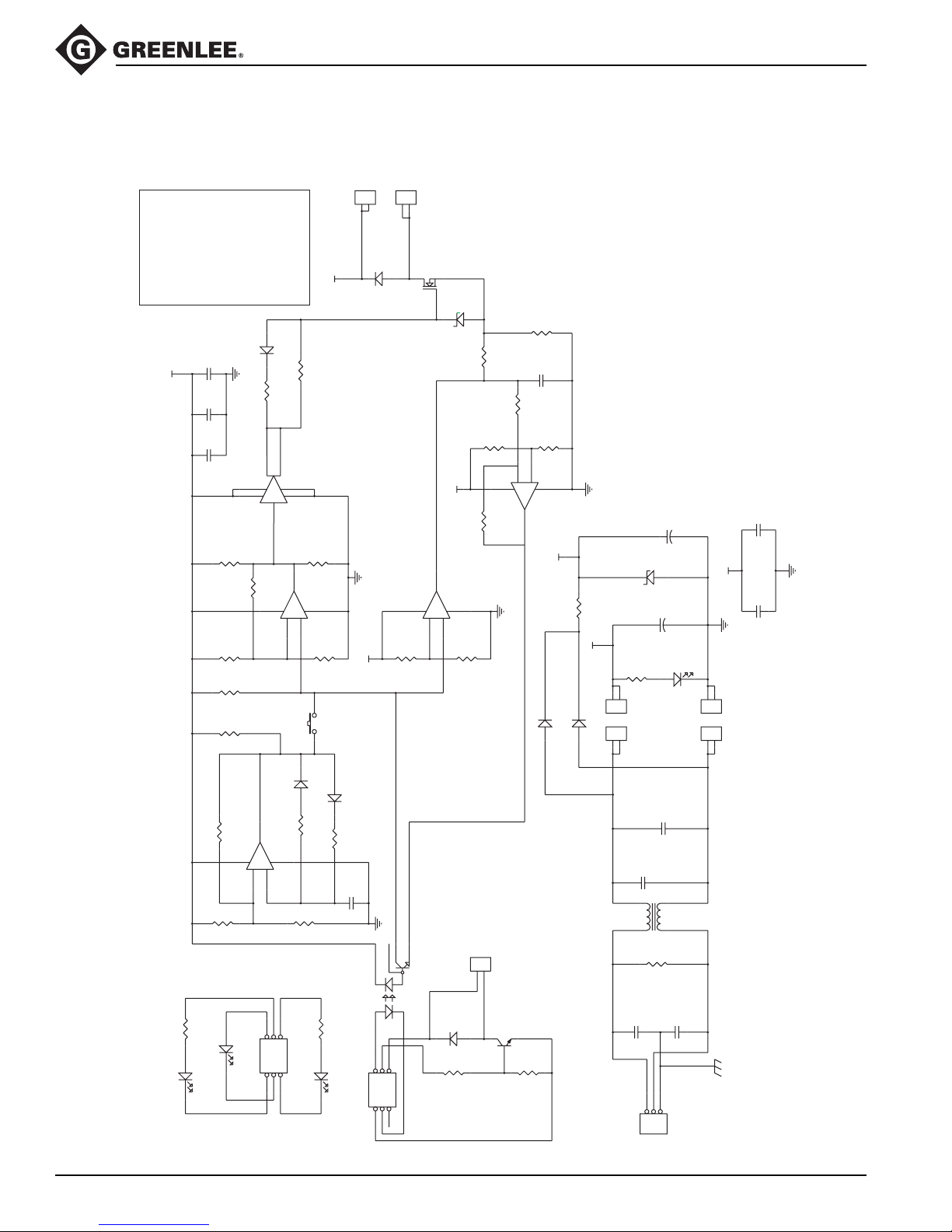
Power Generation Unit Schematic Diagram (500 8357.0)
BLACK
J11
RED
#4-40 Phillips Screw
#4-40 Nut
#4-40 Lock Washer:
#4-40 Flat Washer (x2)
KA-118-094
Power Devices, Inc
Insulator:
THM7023B-MT
Thermalloy Inc.
Heatsink:
Mounting Hardware for Q1 and D8
Do not trim insulator.
in heat sink.
Q1 should mount to upper hole
in heat sink.
D8 should mount to lower hole
Tighten Q1 and D8 to 5 in-lb
J10
1
+170 V
1
2
TO RELAY (Contacts 6 and 7)
D8
DSEI30-06A
2
TO RELAY (Contacts 5 and 8)
IXFK73N30
Q1
D3
1N5245B
.040/5W/1%
R15
853 Quad Bender™
+15 V
1uF/63V
.1uF/50V
.1uF/50V
4.75K/1%
R6
20K/1%
R7
12K/1%
R5
150K
R41M
R2
D5
1N4148
22
R11
22
R9
7
6
MIC4422BN
U2
5
8
4
1
2
1.5K/1%
R26
100K
U1B
2
LM339
+
5
4
123
-
+
6
7
10K/1%
R16
S1
1N4148
D6
D7
100K
R13
R14
123
-
1M
R12
EVQ-PAC09K
1N4148
1M
C3
.01uF/50V
+15 V
8
1
LM339
U1A
R10
R24
20K/1%
567
U1D
13
LM339
+
11
-
10
+15 V
123
R25
R29
10K/1%
J4
68.1K/1%
2
1
R22
R23
18.7K/1%
R27
8
9
+
14
LM339
U1C 100/1%
TO RELAY COIL (Contacts 1 and 2)
Molex 39-28-1023
10K/1%
-
D13
C12
R28
123
.1uF/50V
1.5K/1%
+15 V
R17
1N4007
4.7K/10W
D14
+170 V
1N4007
C10
C71000uF/250V
680uF/25V
D10
1N5245B
C6
POWER
GREEN LED
D11
20K/2W/1%
R18
2
RECTIFIER
C11
.010uF/500VAC
470uH
L1
1
J9
2
1
J8
2
1
DC+
RED
J6
2
1
TO BRIDGE
AC
J5
YELLOW
C4
.010uF/500VAC
1.5M
R20
.1uF/50V.1uF/50V
+15 V
C9
DC-
BLACK
AC
YELLOW
Notes:
• Bend leads on R17 to mount at least 0.25" off-board.
• All resistors 5% 1/4W unless noted.
C2
C13
C1
1M
R3
R1
D1
2K
D2
DIRECTION
YELLOW LED
PWM
RED LED
J1
R8
654321
TEST CONNECTOR
Molex 39-28-1063
D4
Greenlee / A Textron Company 24 4455 Boeing Dr. • Rockford, IL 61109-2988 USA • 815-397-7070
2K
VCC
GREEN LED
U3
J2
2
HCPL4502
3
654321
TO I/O
Molex 39-28-1063
D9
UF1001DI
R19
.0047uF/500VAC
.0047uF/500VAC
C8
PN2222A
Q2
1K
1K
R21
C5
GROUND
NEUTRAL
LINE
321
AC POWER IN
Beau 72503-C
J7
Page 25
853 Quad Bender™
Power Generation Unit Parts List (500 8357.0)
C1,C9,C10,C12,C13 Philips A104K29X7RFVVWN Capacitor, 0.1 uF, 50 volts 5
AVX SA115C104KAA
KEMET C420C104K5R5CA
C2 WIMA MKS21.06310 Capacitor, Film, 1 uF, 63 volts 1
C3 Philips A103M15Z5UFVVWA Capacitor, .01 uF, 50 volts 1
C4,C11 Sprague 440LS10 Capacitor, .010 uF, 500 volts AC 2
C5,C8 Sprague 440LD47 Capacitor, .0047 uF, 500 volts AC 2
C6 Panasonic ECE-S2EU102Z Capacitor, 1000 uF, 250 volts 1
C7 Panasonic EEU-FC1E681 Capacitor, 680 uF, 25 volts 1
D1 Panasonic LN48YP LED, T1, Amber 1
D2 Panasonic LN28RP LED, T1, Red 1
D3,D10 Motorola 1N5245B Zener Diode, 15 volts, 500 milliwatts 2
D4,D11 Panasonic LN38GP LED, T1, Green 2
D5,D6,D7 Generic 1N4148 Diode 3
D8 IXYS DSEI 30-06A Diode, Fast Recovery, 30A, 400-600V, TO-247 (see Note 1) 1
D9 Vishay UF1001DI Diode, Ultra-Fast Switching, 1A, 50V, 50ns, DO-41 1
D13,D14 Generic 1N4007 Diode 2
J1,J2 Molex 39-29-0063 Connector, Minifit Jr., 6-position, Gold 2
J4 Molex 39-29-0023 Connector, Minifit Jr., 2-position, Gold 1
J5,J6,J8,J9,J10,J11 Keystone 1287 Connector, Tab, .250 x .032 6
J7 Beau 72503-C Connector, Terminal Block, 3-position, No Mount Holes 1
L1 Renco RL-1328-22-470 Choke, Common Mode 1
Q1 IXYS IXFK73N30 MOSFET, N channel, 73-76A, 300V, TO-264 (see Note 2) 1
Q2 Generic PN2222A Transistor, NPN 1
R1,R8 Generic Resistor, 2 kΩ, 1/4 watt, 5% 2
R2,R3,R12,R14 Generic Resistor, 1 MΩ, 1/4 watt, 5% 4
R4 Generic Resistor, 150 kΩ, 1/4 watt, 5% 1
R5 Generic Resistor, 12.1 kΩ, 1/4 watt, 1% 1
R6 Generic Resistor, 4.75 kΩ, 1/4 watt, 1% 1
R7,R24 Generic Resistor, 20 kΩ, 1/4 watt, 1% 2
R9,R11 Generic Resistor, 22 Ω, 1/4 watt, 5% 2
R10,R13 Generic Resistor, 100 kΩ, 1/4 watt, 5% 2
R15 Dale LVR-5 .04W Resistor, .040 Ω, 5 watt, 1% 1
R16,R23,R25 Generic Resistor, 10 kΩ, 1/4 watt, 1% 3
R17 Dale CW-10 4.7K Resistor, 4.7 kΩ, 10 watt, 5% (see Note 3) 1
R18 Dale RS-2B-20K Resistor, 20 kΩ, 2 watt, 1% 1
AVX SA105E103ZAA
Cornell Dubilier 380LX102M250K052
Liteon LTL-4251
Liteon LTL-4221
Liteon LTL-4231
Adv Pwr Tech APT30D40B
Adv Pwr Tech APT30D60B
Magnum A202203
Adv Pwr Tech APT30M40LVFR
KRL NP-5A .04W
Riedon MT-5 .04W
KRL C-10A 4.7K
Riedon UT-10 4.7K
KRL C-2A 20K
Riedon UT-2B 20K
Greenlee / A Textron Company 25 4455 Boeing Dr. • Rockford, IL 61109-2988 USA • 815-397-7070
Page 26

853 Quad Bender™
Power Generation Unit Parts List (500 8357.0) (cont’d)
R19,R21 Generic Resistor, 1 kΩ, 1/4 watt, 5% 2
R20 Generic Resistor, 1.5 MΩ, 1/4 watt, 5% 1
R22 Generic Resistor, 100 Ω, 1/4 watt, 1% 1
R26,R28 Generic Resistor, 1.5 kΩ, 1/4 watt, 1% 2
R27 Generic Resistor, 18.7 kΩ, 1/4 watt, 1% 1
R29 Generic Resistor, 68.1 kΩ, 1/4 watt, 1% 1
S1 Panasonic EVQ-PAC09K Switch, Momentary Pushbutton 1
U1 Motorola LM339AN IC, Low Power Quad Comparitor 1
U2 Micrel MIC4422BN IC, 9-A Peak Low-Side Non-inverting MOSFET Driver 1
U3 HP HCPL4502 IC, Opto-isolator 1
QT-Opto HCPL4502
Siemens 6N136
Note 1: Mount D8 to bottom hole of heat sink.
Note 2: Mount Q1 to top hole of heat sink.
Note 3: Bend leads and mount .25" off-board .
Greenlee / A Textron Company 26 4455 Boeing Dr. • Rockford, IL 61109-2988 USA • 815-397-7070
Page 27

Layout Diagram — Power Generation Unit (500 8357.0)
853 Quad Bender™
TO I/OGround Neutral Line
654
J2
321
U3
C10
R2
R5
R13
R12
C3C1C9
R14
R25 R19
RedBlack
D8
R4
R3
S1
D6
D7
J10J11
TO RELAY
R16
R21
R24
Q2
1
D9
R10
R7
R28
R27
R15
321
D2
PWM
TEST
2
+
J4
C7
R6
R26
U1
R23
C12
D3
Q1
C13
R22
654
C2
D5
R8
D10
R9
D11
POWER
DIR
D1
R1
U2
R11
R18
VCC
D4
C5
R17
L1
+
C6
Red Black
J6
J7
D14
C8
C11
C4
J5
J8
R20
D13
YellowYellow
GREENLEE TEXTRON
©2000
J9
FROM RECTIFIER
Greenlee / A Textron Company 27 4455 Boeing Dr. • Rockford, IL 61109-2988 USA • 815-397-7070
Page 28

USA 800-435-0786 Fax: 800-451-2632
815-397-7070 Fax: 815-397-1865
Canada 800-435-0786 Fax: 800-524-2853
International +1-815-397-7070 Fax: +1-815-397-9247
4455 Boeing Drive • Rockford, IL 61109-2988 • USA • 815-397-7070
An ISO 9001 Company
www.greenlee.com
•
Greenlee Textron Inc. is a subsidiary of Textron Inc.
Printed in USA
 Loading...