

Page 1
INSTRUCTION MANUAL
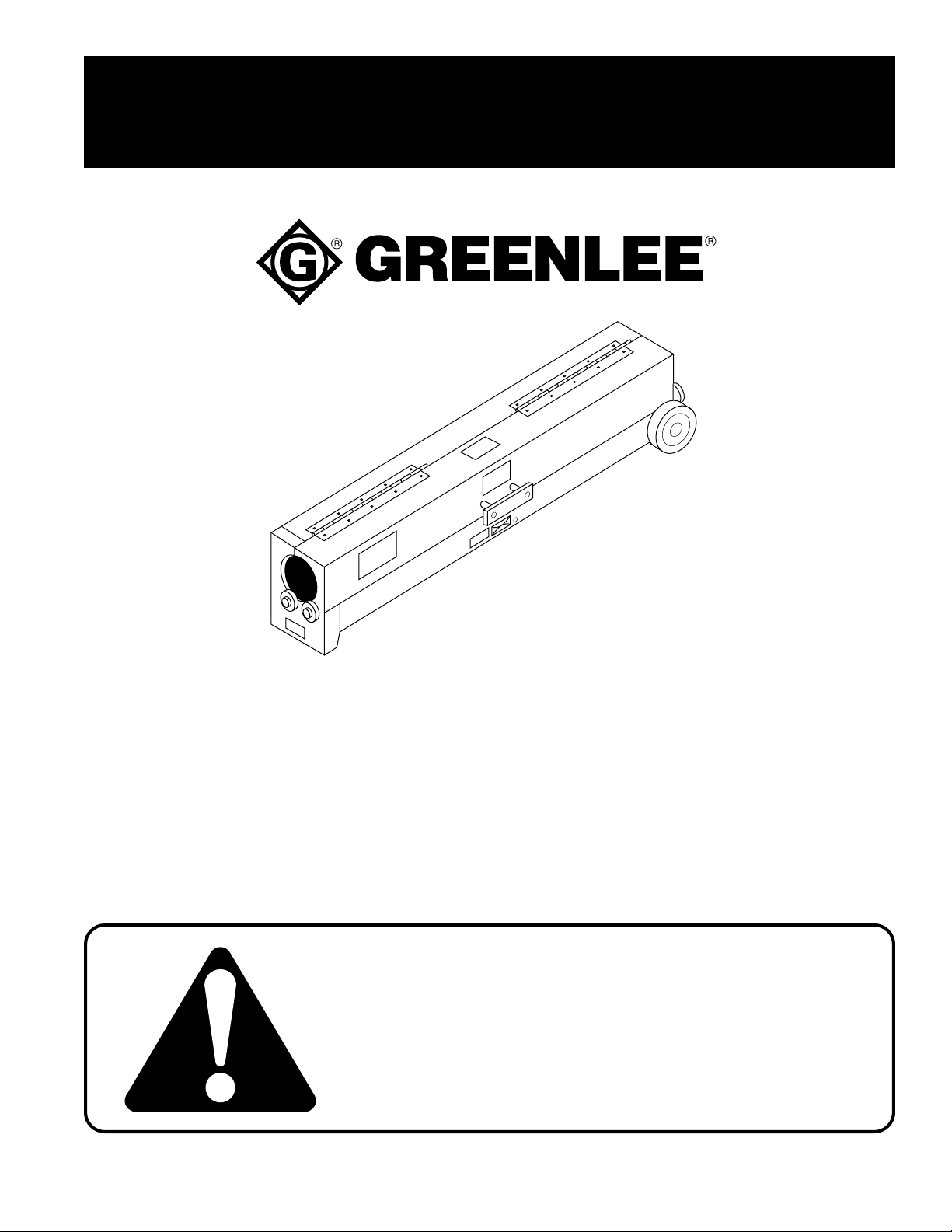
MODELS 851
PVC HEATER
for 1/2" - 4" Dia. PVC Conduit
Read and understand this material before operating
or servicing this equipment. Failure to understand how
to safely operate this tool could result in an accident
causing serious injury or death.
999 0004.1 © 1998 Greenlee Textron IM 1094 REV 3 6/98
Find Quality Products Online at: [email protected]
www.GlobalTestSupply.com
Page 2

Table of Contents
Description and Purpose ......................................................................................2
Important Safety Instructions............................................................................ 3-5
Specifications........................................................................................................6
Operation ..............................................................................................................6
Troubleshooting ....................................................................................................7
Wiring Diagram .....................................................................................................7
Exploded View ......................................................................................................8
Parts List ...............................................................................................................9
851 Heater for PVC Conduit
Description
Purpose
The Greenlee 851 PVC Heater is intended to heat plastic conduit for bending.
Optional accessories include Greenlee Model 857 PVC Roller Support for
supporting long pieces of conduit, and PVC Plugs to help prevent the PVC from
collapsing. See a Greenlee catalog for more information.
This instruction manual is intended to familiarize operators and maintenance
personnel with the safe operation and maintenance procedures for the Greenlee
851 PVC Heater. This manual should be kept available to all operating and
maintenance personnel.
Greenlee Textron / Subsidiary of Textron Inc.
Find Quality Products Online at: [email protected]
www.GlobalTestSupply.com
2
4455 Boeing Dr., Rockford, IL 61109-2988 815/397-7070
Page 3
851 Heater for PVC Conduit
IMPORTANT SAFETY INSTR UCTIONS
SAFETY
ALERT
Immediate hazards which, if not avoided, WILL result in
severe personal injury or death.
SYMBOL
The symbol above is used to call your attention
to instructions concerning your personal safety.
Watch for this symbol. It points out important safety
precautions. It means “ATTENTION! Become alert!
Your personal safety is involved!” Read the
message that follows and be alert to the possibility
of personal injury or death.
Safety is a critical factor in the design of Greenlee equipment. The best program starts with a safety-conscious
operator. The information highlighted in this bulletin describes operating practices for the benefit of the workers
who will use our equipment in their daily jobs. Comments from users are appreciated.
A person who has not read and does not understand all
operating instructions is not qualified to operate this tool.
Failure to read and understand safety instructions could
result in injury or death.
Hazards or unsafe practices which, if not avoided, COULD
result in severe personal injury or death.
Hazards or unsafe practices which, if not avoided, COULD
result in minor personal injury or property damage.
SA VE THESE INSTRUCTIONS
Additional copies of this manual are available upon request at no charge.
Greenlee Textron / Subsidiary of Textron Inc.
Find Quality Products Online at: [email protected]
www.GlobalTestSupply.com
3
4455 Boeing Dr., Rockford, IL 61109-2988 815/397-7070
Page 4
851 Heater for PVC Conduit
IMPORTANT SAFETY INSTR UCTIONS
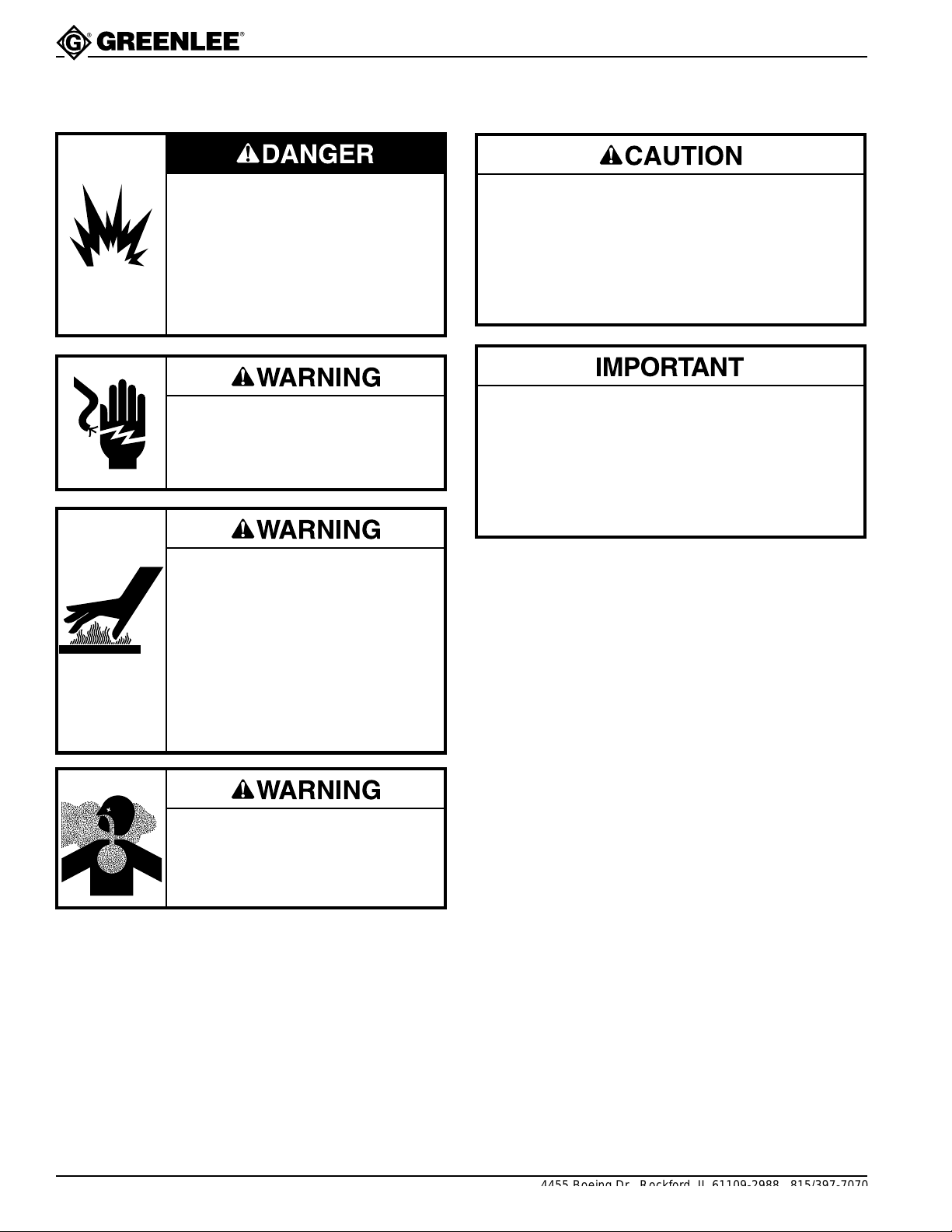
Do not use this heater in a hazardous environment. Hazards include
flammable liquids, gases, or other
materials. Using this heater in a
hazardous environment can result
in a fire or explosion.
Failure to observe this warning will
result in severe injury or death.
Electric Shock Hazard. Do not
expose heater to rain or moisture.
Failure to observe this warning can
cause severe injury or death.
Heater temperature will exceed
538° C (1000° F).
• Wear insulated gloves when using
this heater and when bending
PVC.
• Do not leave heater unattended.
• Unplug when not in use.
Failure to observe these warnings
can result in severe burns.
• Inspect tool before operating. Replace any worn,
damaged or missing components with Greenlee
replacement parts.
• Use this heater for manufacturer’s intended
purpose only. Do not use as a space heater. Use
other than that which is described in this manual
can result in injury or property damage.
If using an extension cord, use one with the
following characteristics:
• 14 AWG minimum
• 45 meters (150') maximum
Using a lighter gauge or longer cord will cause a
loss of heating power.
Use in a well-ventilated area. Hot
PVC will give off fumes. Failure to
observe this warning or precaution
can result in serious injury or injury.
SA VE THESE INSTRUCTIONS
Additional copies of this manual are available upon request at no charge.
Greenlee Textron / Subsidiary of Textron Inc.
Find Quality Products Online at: [email protected]
www.GlobalTestSupply.com
4
4455 Boeing Dr., Rockford, IL 61109-2988 815/397-7070
Page 5
851 Heater for PVC Conduit
IMPORTANT SAFETY INSTR UCTIONS
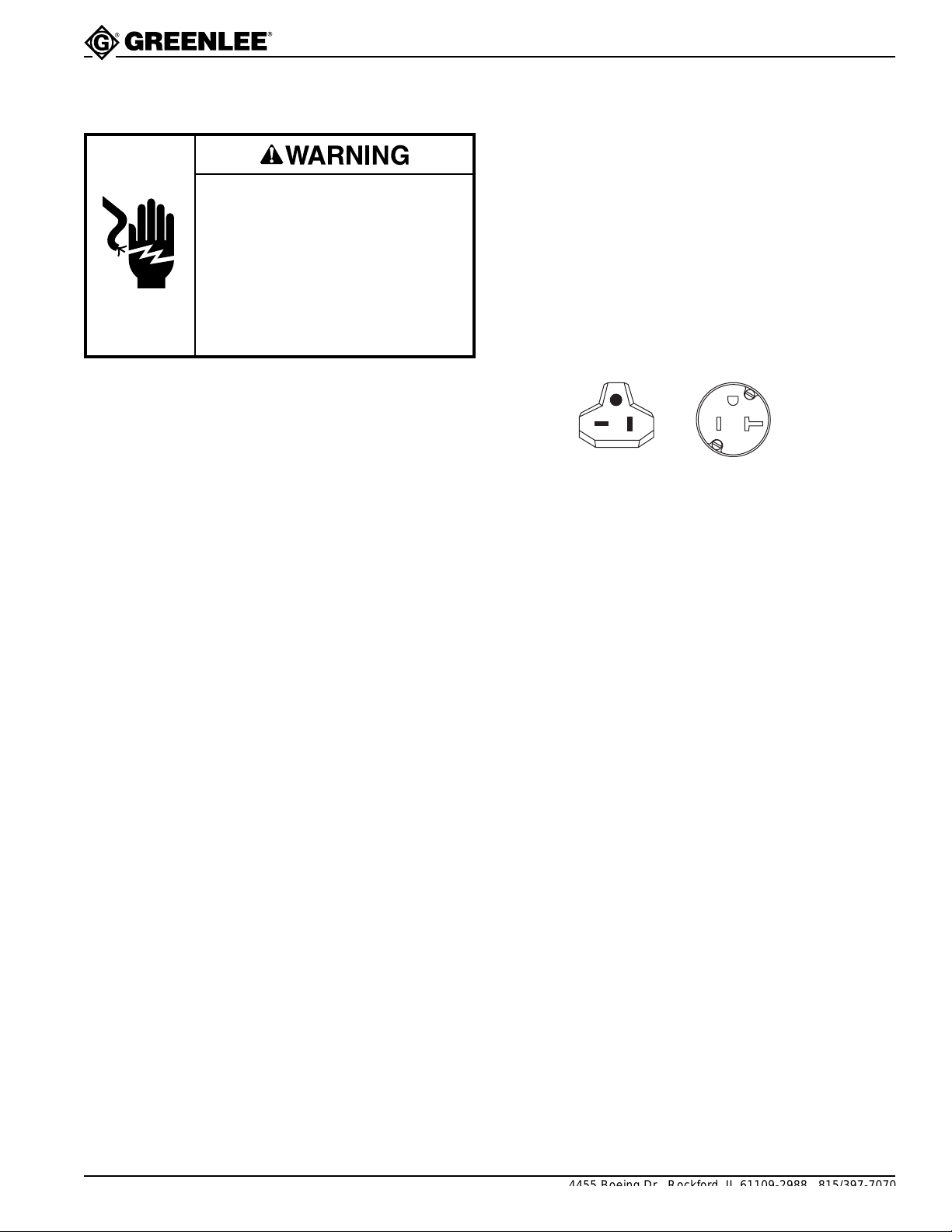
This tool must be grounded. In the event of a malfunction or breakdown, an electrical ground provides a path
of least resistance for the electric current. This path of
Electric shock hazard.
• Do not modify the plug provided
with the tool.
• Connect this tool to a grounded
receptacle on a 20-amp GFCIprotected circuit.
Failure to observe these warnings
can result in severe injury or death.
least resistance is intended to reduce the risk of electric
shock.
This tool’s electric cord has a grounding conductor and
a grounding plug as shown. Do not modify the plug.
Connect the plug to a corresponding 20-amp GFCI
protected receptacle that is properly installed and
grounded in accordance with all national and local
codes and ordinances. Do not use an adapter.
PLUG RECEPTACLE
Greenlee Textron / Subsidiary of Textron Inc.
Find Quality Products Online at: [email protected]
www.GlobalTestSupply.com
5
4455 Boeing Dr., Rockford, IL 61109-2988 815/397-7070
Page 6
Specifications
Power ........................................................................... 120 Volts, 20 Amps, 60 Hz
Capacity:
Dimensions ..........................................22 cm x 30 cm x 137 cm (8.5" x 12" x 54")
Mass/Weight ....................................................................................24 kg (53 lbs.)
851 Heater for PVC Conduit
Conduit Diameter.......................................................... 1/2" – 4" PVC Conduit
Conduit Length ............................................................................ 137 cm (54")
Operation
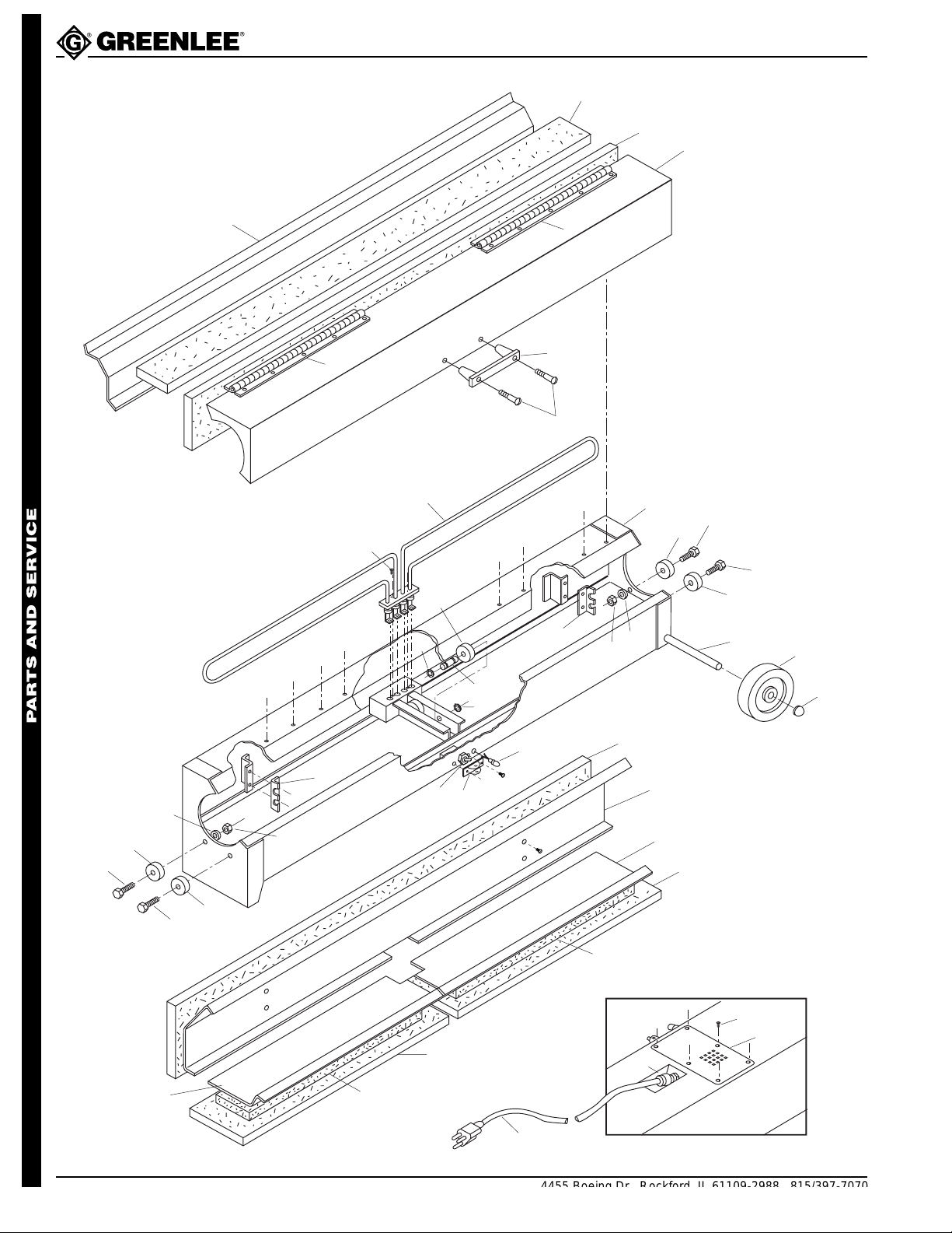
See the Exploded View. Remove the handle from the
inside of the PVC heater and attach it to the cover.
When bending 2"or larger conduit, Greenlee recommends using 859-series PVC plugs. Install one plug in
each end of the conduit and tighten the wing nut until
the conduit is sealed. Remove the plugs after the PVC
has cooled.
1. Place the heater on a firm, flat surface.
2. Plug the cord in. Turn the heater ON. The pilot light
will illuminate.
3. Place the conduit on the rollers and close the cover.
Rotate the conduit by hand.
4. Check the PVC by lifting it at one end. When the
PVC is flexible, open the cover and remove the
conduit.
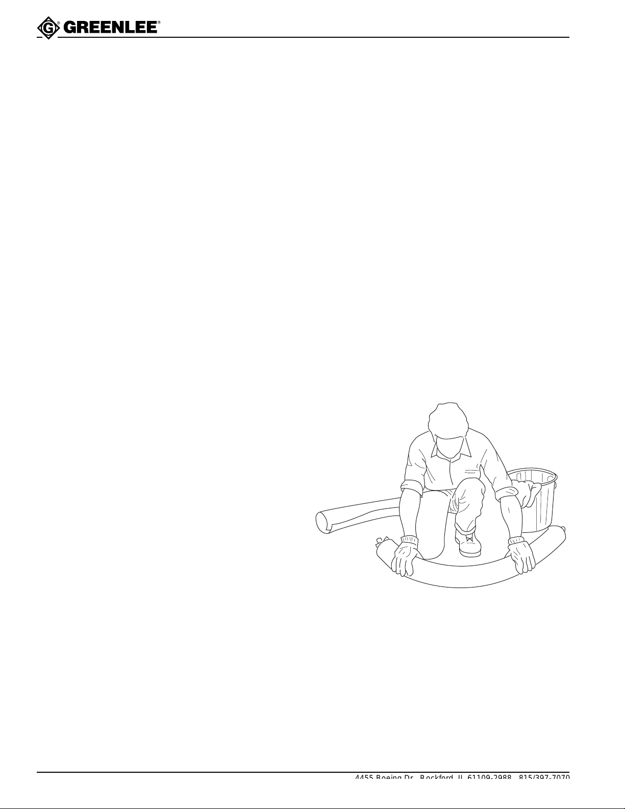
5. Place the PVC on a flat surface. Form the bend by
hand. Allow the PVC to cool or set the bend by
applying cool water with a sponge or rag.
Greenlee Textron / Subsidiary of Textron Inc.
Find Quality Products Online at: [email protected]
www.GlobalTestSupply.com
6
4455 Boeing Dr., Rockford, IL 61109-2988 815/397-7070
Page 7
Troubleshooting
851 Heater for PVC Conduit
PROBLEM PROBABLE REMEDY
PROBABLE CAUSE
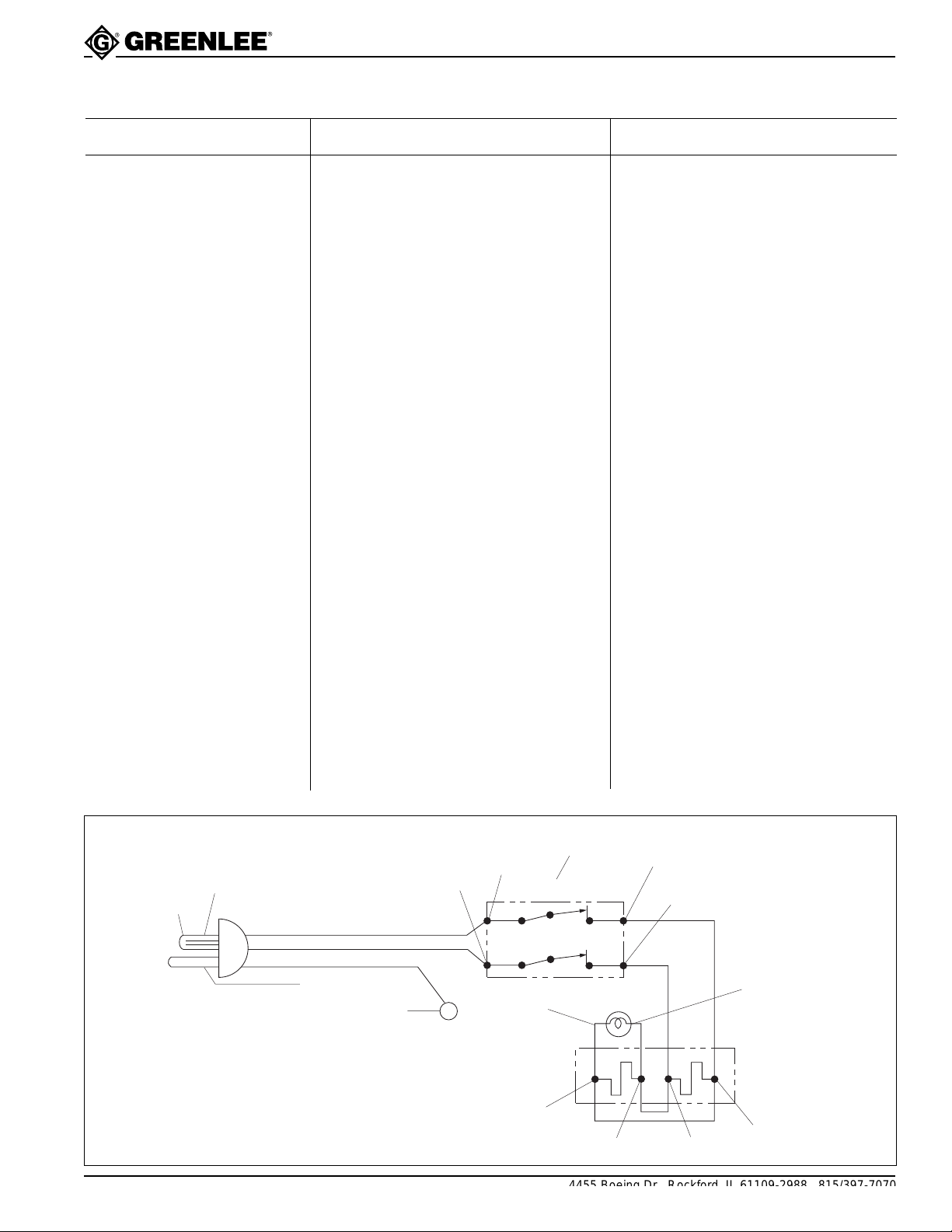
Pilot light does not light up. Pilot light is faulty. Disconnect power. Check continuity
between terminals 13 and 14. Replace
pilot light if this terminal pair does not
have continuity.
Heater does not heat up. No power at supply circuit. Check power supply with a voltmeter.
Verify that the circuit has the appropriate voltage and current rating.
See the Specifications section of this
manual.
Switch is faulty. Disconnect power. Turn the power
switch to the ON position. Check
continuity between:
• terminals 4 and 8
• terminals 5 and 7
Replace the switch if either terminal
pair does not have continuity.
Heating element is faulty. Disconnect power. Allow heating
elements to cool. Disconnect wires at
terminals 9, 10, 11 and 12.
Check continuity between:
• terminals 9 and 10
• terminals 10 and 11
Replace the corresponding heating
element if either terminal pair does
not have continuity.
Wiring Diagram
2
1
Power cord is faulty. Disconnect power. Check continuity
between:
• terminals 1 and 4
• terminals 2 and 5
• terminals 3 and 6
Replace the power cord if any terminal
pair does not have continuity.
WHITE
3
BLACK
6
GROUND
15
4
5
SWITCH
14
12
PILOT LIGHT
11
8
7
13
HEATING
ELEMENT
9
10
Greenlee Textron / Subsidiary of Textron Inc.
Find Quality Products Online at: [email protected]
www.GlobalTestSupply.com
7
4455 Boeing Dr., Rockford, IL 61109-2988 815/397-7070
Page 8
851 Heater for PVC Conduit
Exploded View
2
3
1
4
5
11
10
6
5
7
12
14
13
14
13
16
14
13
15
17
19
22
13
28
21
19
18
23
17
29
16
15
25
BOTTOM VIEW
32
26
27
28
13
34
24
14
8
9
33
30
Greenlee Textron / Subsidiary of Textron Inc.
Find Quality Products Online at: [email protected]
www.GlobalTestSupply.com
29
31
8
4455 Boeing Dr., Rockford, IL 61109-2988 815/397-7070
Page 9

Parts List
851 Heater for PVC Conduit
1 503 5583.0 Cover unit (includes 2 – 5) ............................................1
2 503 5595.3 Insulation, top cover ......................................................1
3 503 5594.5 Insulation, rear cover.....................................................1
4 503 5590.2 Reflector, cover .............................................................1
5 905 2970.7 Handle ...........................................................................1
6 503 5598.8 Hinge .............................................................................2
7 905 2969.3 Screw, machine, #10 – 24 x 2.00 round head ..............2
8 905 3296.1 Wheel ............................................................................2
9 905 2265.6 Retainer, push-on..........................................................2
10 905 0704.5 Screw, machine, #10 – 32 x .375 round head ..............2
11 503 5592.9 Heating element ............................................................1
12 503 5582.1 Housing unit ..................................................................1
13 905 2971.5 Wheel ............................................................................6
14 905 0877.7 Screw, cap, 1/4 – 20 x 1.250 hex head ........................4
15 905 1593.5 Nut, hex, 1/4 – 20..........................................................4
16 905 2339.3 Washer, flat, .312 x .750 x .090 ....................................4
17 503 5601.1 Bracket, heating element ..............................................2
18 503 5599.6 Pin, roller .......................................................................2
19 905 0937.4 Retaining ring, .250, Truarc #5100-25 ..........................4
21 918 6410.0 Guard, switch ................................................................1
22 918 6409.7 Switch, toggle................................................................1
23 918 6091.1 Pilot light........................................................................1
24 503 5600.3 Axle, wheel....................................................................1
25 503 5596.1 Insulation, rear ..............................................................1
26 503 5587.2 Reflector, rear ...............................................................1
27 503 6311.5 Reflector, lower right .....................................................1
28 503 5597.0 Insulation, bottom..........................................................2
29 503 7189.4 Insulation, lower reflector ..............................................2
30 503 6310.7 Reflector, lower left .......................................................1
31 503 5603.8 Cord, power...................................................................1
32 918 6441.0 Grip, cord.......................................................................1
33 503 5593.7 Cover, electrical ............................................................1
34 905 2401.2 Screw, #10 – 32 x .375 .................................................7
Decals and Warning Plate
503 6097.3 Plate, Hot Warning ........................................................1
503 6098.1 Decal, Lift Point .............................................................1
503 6096.5 Decal, Use GFCI Cord ..................................................1
503 5191.5 Decal, Safety Instruction ...............................................1
503 0392.9 Decal, Damp Warning ...................................................1
Greenlee Textron / Subsidiary of Textron Inc.
Find Quality Products Online at: [email protected]
www.GlobalTestSupply.com
9
4455 Boeing Dr., Rockford, IL 61109-2988 815/397-7070
 Loading...