

Page 1
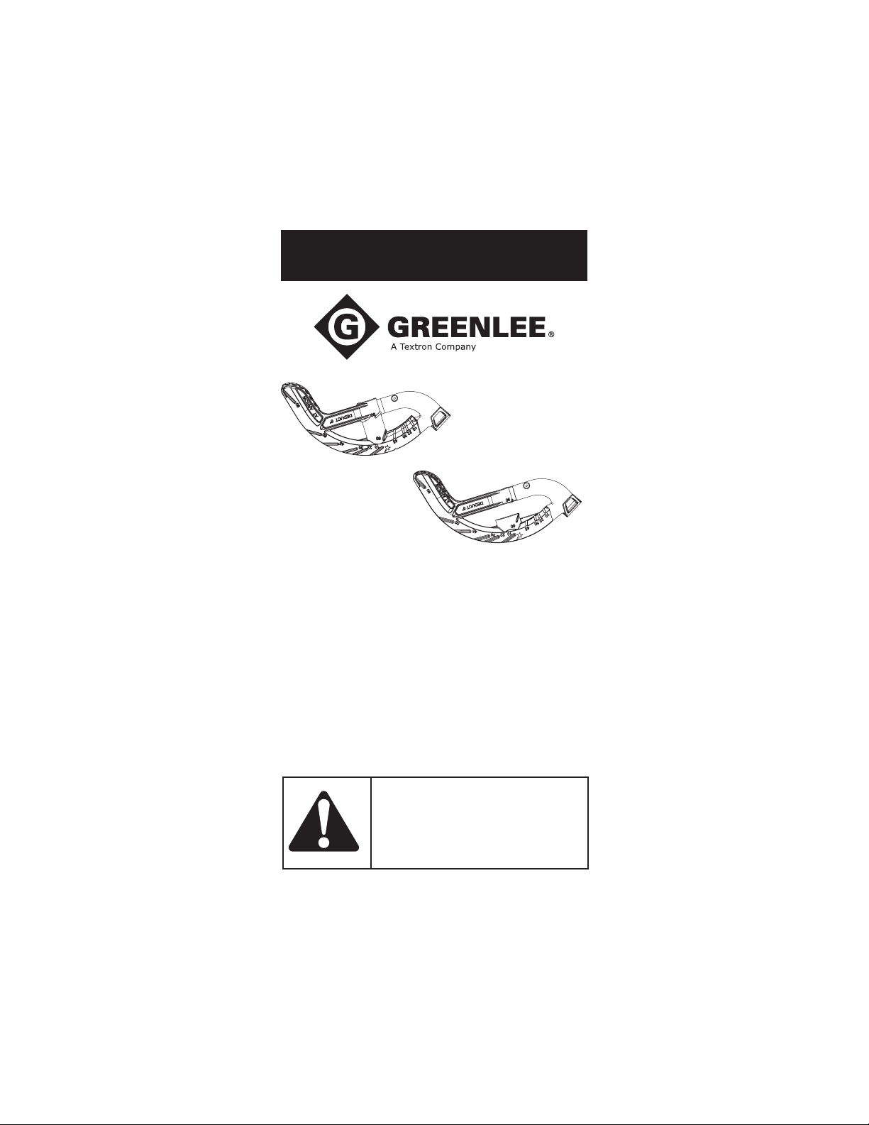
INSTRUCTION MANUAL
ALUMINUM SITE-RITE
®
HAND BENDERS
840A, 841A, 842A, 843A,
840AH, 841AH and 842AH
AND
IRON SITE-RITE
840F, 841F, 842F, 843F,
840FH, 841FH, and 842FH
Read and understand this material
before operating or servicing this
equipment. Failure to understand how to
safely operate this tool could result in an
accident causing serious injury or death.
52034125 © 2008 Greenlee Textron Inc. 4/08
®
HAND BENDERS
Find Quality Products Online at: [email protected]
www.GlobalTestSupply.com
Page 2
SITE-RITE® Hand Benders
Description
The Greenlee aluminum SITE-RITE® and iron SITE-RITE® benders are
manually powered tools intended to bend 1/2" through 1-1/4" EMT
(electrical metallic tubing) and 1/2" through 1" rigid and IMC conduit.
Purpose
This instruction manual is intended to familiarize operators and
maintenance personnel with the safe operation of the Greenlee
SITE-RITE® Manual Benders. This manual should be kept available to all
operating personnel.
A person who has not read and does not
understand all operating instructions is not
qualified to operate this tool.
Failure to read and understand safety instructions
may result in injury or property damage.
Inspect the tool for wear or damage. Replace worn, damaged,
or missing components with Greenlee replacement parts.
A worn, damaged, or improperly assembled component may fail,
resulting in injury or property damage.
Use this tool for manufacturer’s intended use only. Use other than
that for which the tool was intended may result in injury.
All specifications are nominal and may change as design improvements
occur. Greenlee Textron Inc. shall not be liable for damages resulting
from misapplication or misuse of its products.
KEEP THIS MANUAL
Additional copies of this manual are available
upon request at no charge.
2
Find Quality Products Online at: [email protected]
www.GlobalTestSupply.com
Greenlee / A Textron Company
Page 3
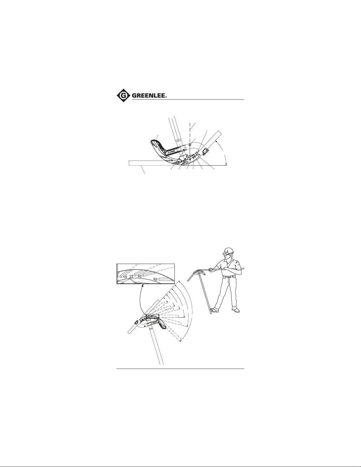
Bending — Handle Up
APPLY FOOT
PRESSURE HERE
SITE-RITE® Hand Benders
LINE OF
SIGHT
ARROW
PIN
45°
FLOOR LINE
90° 60° 45° 30° 22-1/2° 10°
1. Mark the conduit.
2. Insert the conduit into the bender so that the arrow is aligned with
the bending mark.
Place one foot on the bender as illustrated. Use heavy foot pressure
3.
on the bending shoe; maintain this pressure throughout the bend.
4. Look down the line of sight as illustrated. Stop bending when the
pin is in line with the appropriate angle mark.
Note: Overbend rigid conduit slightly to compensate for springback.
Bending — Handle Down
10°
221/2°
30°
45°
60°
90°
3
Find Quality Products Online at: [email protected]
www.GlobalTestSupply.com
Page 4
SITE-RITE® Hand Benders
Bending — Handle Down (cont’d)
1. Mark the conduit.
2. Insert the conduit into the bender so that the arrow is aligned with
the bending mark.
3. Position the bender as shown, with your body as close to the bender
as possible.
4. With the handle angled to prevent slipping, apply constant pressure
against the conduit throughout the bend.
5. Bend until the edge of the conduit is in line with the degree scale as
illustrated.
Note: Overbend rigid conduit slightly to compensate for springback.
Bending Tips:
• Line up all bends in the same plane.
• Bend 1/2" and 3/4" EMT with the handle down.
• Bend 1" and 1-1/4" conduit with the handle up.
• When bending with the handle up, work at a stairwell or loading dock
so that previously made bends hang over the edge.
Marking the Conduit for 90° Stubs
Arrow
Mark A
HEIGHT
OF
STUB
DEDUCT
HEIGHT OF STUB
Mark B
1. Measure the length of the required stub.
2. Measure and mark the stub length on the conduit. This is Mark A.
3. See the Deduct length shown on the bender. Subtract the Deduct
length from Mark A and make a new mark. This is Mark B.
4. Align Mark B with the arrow on the bender and bend the conduit
to 90°.
4
Find Quality Products Online at: [email protected]
www.GlobalTestSupply.com
Greenlee / A Textron Company
Page 5
SITE-RITE® Hand Benders
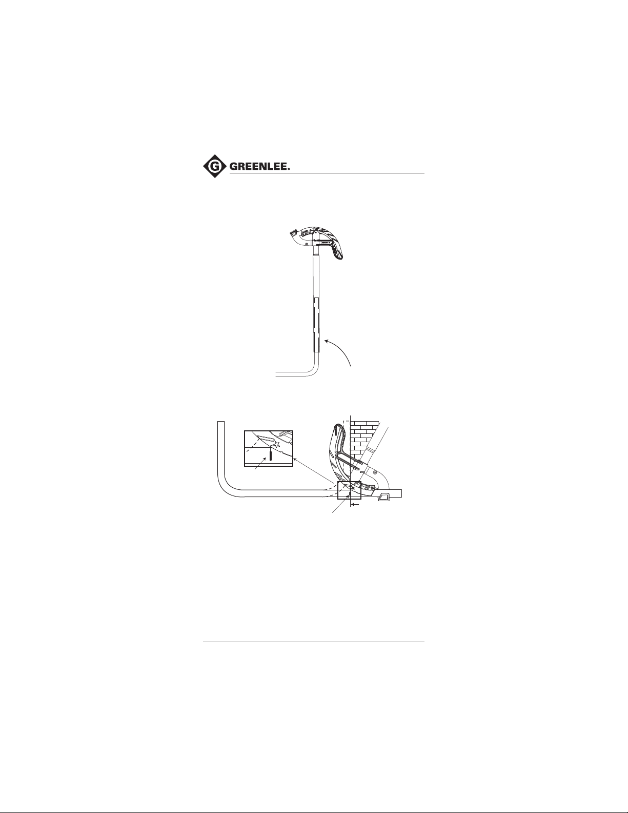
Correcting Overbends
If a stub-up is accidentally overbent, place the open end of the bender
handle over the conduit and manipulate to desired angle.
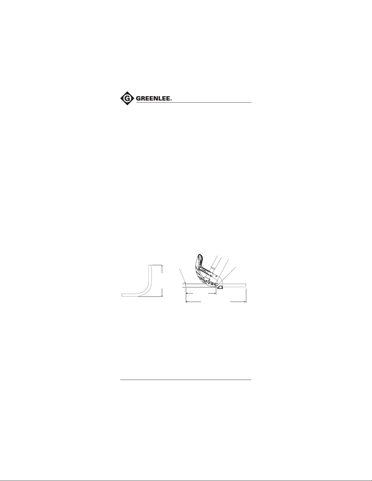
Back-to-Back 90° Stubs
MARK
FINISH LINE
MARK
1. Make the first 90° stub.
2. Fit the bent conduit into its final position and mark the Finish Line
on the conduit, as shown. The Finish Line on the conduit is the
bending mark.
3. Align the bending mark with the tip of the star and bend the conduit
to 90°.
5
Find Quality Products Online at: [email protected]
www.GlobalTestSupply.com
Page 6
SITE-RITE® Hand Benders
Offset Bends
An offset is used to re-route the conduit to avoid an obstruction.
An offset consists of two equal opposing bends.
Two factors must be considered when selecting the offset angle. First, a
steeper bend angle will require more pulling force. Second, a shallower
bend angle will require more space.
Greenlee Offset Table
(applies to any size conduit)
Offset Angle Multiplier
10° x 10° 6.0 1/16" per inch
22-1/2° x 22-1/2° 2.6 3/16" per inch
30° x 30° 2.0 1/4" per inch
45° x 45° 1.4 3/8" per inch
60° x 60° 1.2 1/2" per inch
Shrink Per Inch
of Offset Depth
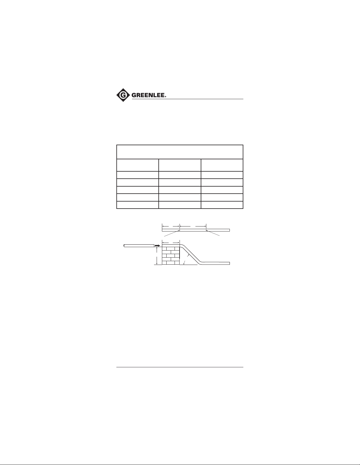
Working Past an Obstruction
14"8"
MARK A
8"
10" DEPTH
OBSTRUCTION
Example 1: Working Past an Obstruction
1. Determine the center-to-center distance. Use one of these two
• Find the appropriate multiplier in the Offset Table, Column 2.
•
2. Mark the conduit as shown.
3. See the bending instructions.
6
45° x 45°, 10 inches of offset
methods:
(For 45° x 45°, the multiplier is 1.4). Multiply the height of the
obstruction by the multiplier (10" x 1.4 = 14).
See the Greenlee Speed Guide for Offsets. In the Offset Depth Inches
column, find the row with the appropriate amount of offset. Find
the Center-to-Center column under the appropriate OFFSET ANGLE.
The distance shown at the intersection of the appropriate row and
column is the center-to-center distance. (Under Offset Depth Inches,
see the row labeled “10”. Read to the right to find the Center-toCenter distance under 45° x 45°. The number shown is 14".)
45°
Greenlee / A Textron Company
MARK B
Find Quality Products Online at: [email protected]
www.GlobalTestSupply.com
Page 7
SITE-RITE® Hand Benders
Working Toward an Obstruction
When working toward an obstruction, the conduit will appear to “shrink.”
To compensate for shrinkage, use the shrink per inch of offset as
shown in the Offset Table, Column 3 or the Shrink Amount shown in the
Greenlee Speed Guide for Offsets.
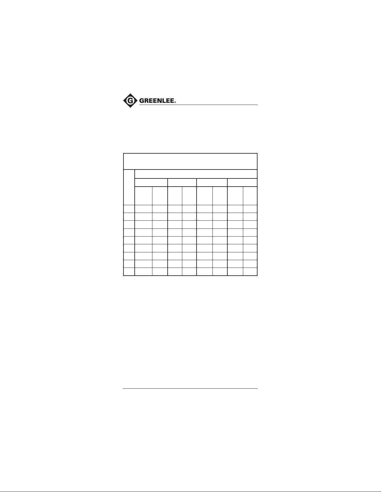
Greenlee Speed Guide for Offsets
(applies to any size conduit)
Offset Angle
22-1/2° x 22-1/2°
Offset
Center
-to-
Center
Shrink
Amount
1-5/16"
Depth
Inches
2 5-1/4" 3/8"
3 7-3/4" 9/16" 6" 3/4"
4 10-1/2" 3/4" 8" 1"
5 13" 15/16" 10" 1-1/4" 7" 1-7/8"
6 15-1/2" 1-1/8" 12" 1-1/2" 8-1/2" 2-1/4" 7-1/4" 3"
7 18-1/4"
8 20-3/4" 1-1/2" 16" 2" 11-1/4" 3" 9-5/8" 4"
9 23-1/2" 1-3/4" 18" 2-1/4" 12-1/2" 3-3/8"
10 26" 1-7/8" 20" 2-1/2" 14" 3-3/4 12" 5"
30° x 30° 45° x 45° 60° x 60°
Center
-to-
Center
14" 1-3/4" 9-3/4" 2-5/8" 8-3/8" 3-1/2"
Shrink
Amount
Center
-to-
Center
Shrink
Amount
Center
-to-
Center
10-7/8"
Shrink
Amount
4-1/2"
7
Find Quality Products Online at: [email protected]
www.GlobalTestSupply.com
Page 8
SITE-RITE® Hand Benders
Working Toward an Obstruction (cont’d)
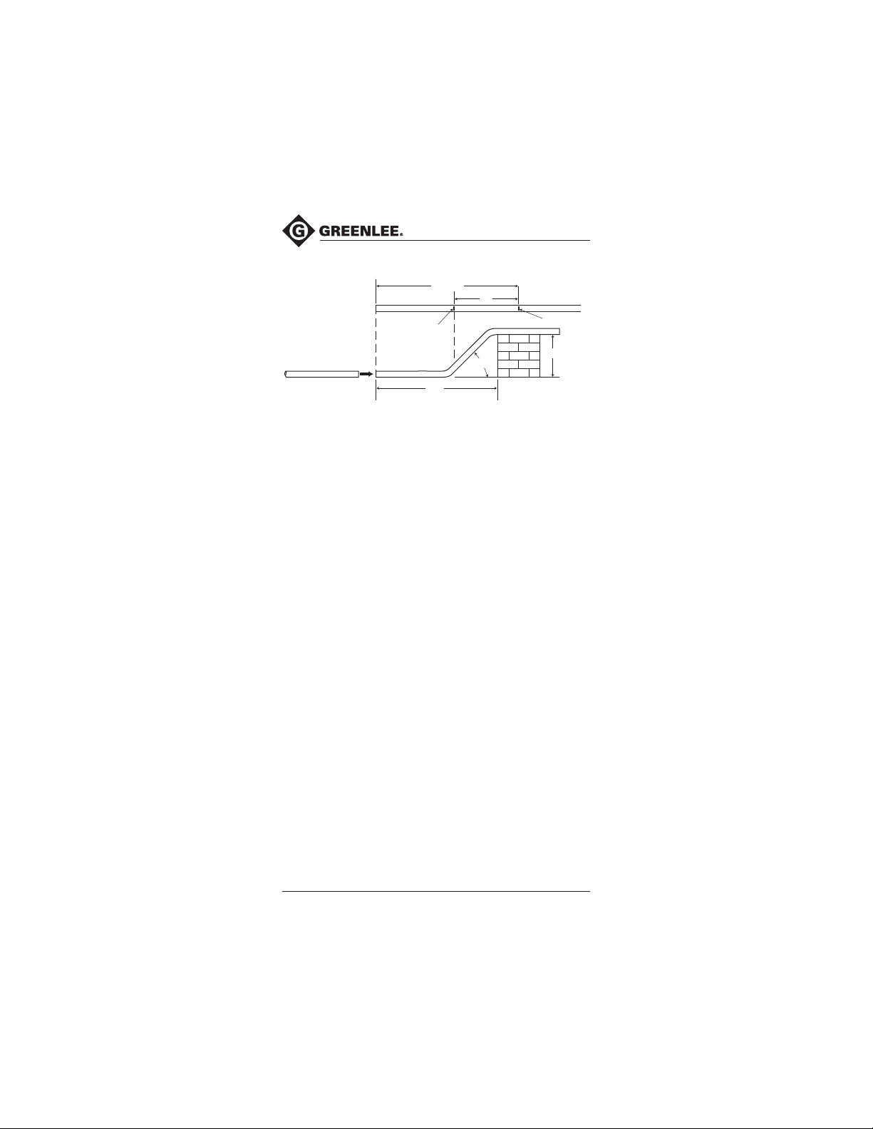
33-3/4"
14"
MARK B
MARK A
45°
30"
Example 2: 45° x 45°, Working Toward an Obstruction
10 inches of offset
1. Calculate the shrinkage. See the Offset Table, Column 3. (The
amount of shrink for 45° x 45° offsets is 3/8" per inch of offset
depth. 3/8 x 10 = 3-3/4")
2. Measure the distance to the obstruction. Add the shrinkage to this
distance. (See the illustration. The distance to the obstruction is 30".
30" + 3-3/4" = 33-3/4)
3. Determine the center-to-center distance. Use one of these two
methods:
• Find the appropriate multiplier in the Offset Table, Column 2.
(For 45° x 45°, the multiplier is 1.4). Multiply the height of the
obstruction by the multiplier (10" x 1.4 = 14).
• See the Greenlee Speed Guide for Offsets. In the Offset Depth
Inches column, find the row with the appropriate amount of offset.
Find the Center-to-Center column under the appropriate OFFSET
ANGLE. The distance shown at the intersection of the appropriate
row and column is the center-to-center distance. (Under Offset
Depth Inches, see the row labeled “10”. Read to the right to find
the Center-to-Center distance under 45° x 45°. The number
shown is 14".)
4. Mark the conduit as shown.
5. See the bending instructions.
OBSTRUCTION
10" DEPTH
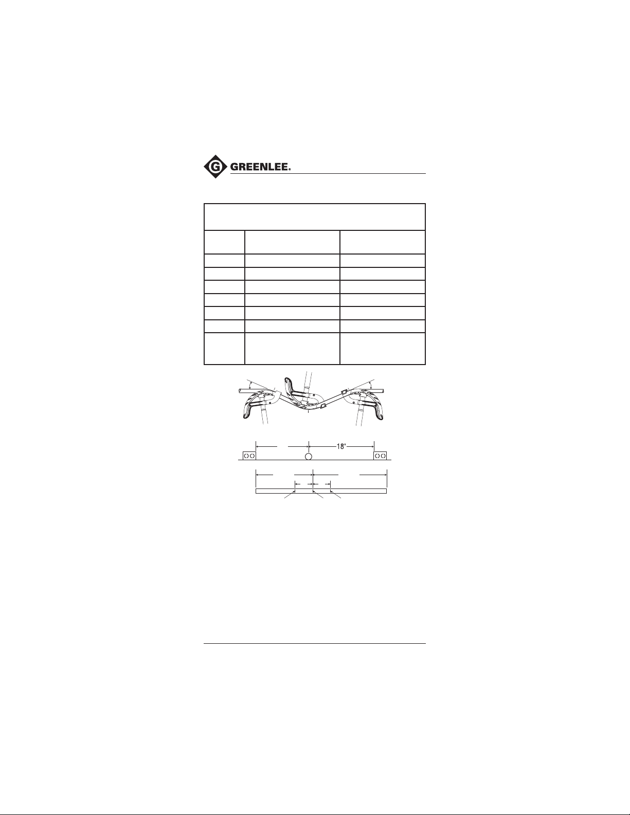
3-Bend Saddles
Like an offset, a saddle is used to avoid an obstruction. In this case,
three bends are used. The first and last bends are of the same degree;
the center bend is twice the number of degrees of the other two bends.
See the illustrations.
8
Find Quality Products Online at: [email protected]
www.GlobalTestSupply.com
Greenlee / A Textron Company
Page 9
SITE-RITE® Hand Benders
3-Bend Saddles (cont’d)
Table for 45° Saddles
(applies to any size conduit)
Saddle
Depth
1" 3/16" 2-1/2"
2" 3/8" 5"
3" 9/16" 7-1/2"
4" 3/4" 10"
5" 15/16" 12-1/2"
6" 1-1/8" 15"
For each
additional
inch add:
Place center Mark “A”
ahead of actual center by
3/16" 2-1/2"
Place Marks “B” & “C”
each way from center
22-1/2°
Example 3: 3-Bend Saddle 45° center bend, 2" obstacle
1. Calculate the shrinkage. See the Greenlee Offset Table, Column 3.
(The amount of shrink for a 22-1/2° bend is 3/16" per inch of
obstacle. 3/16" x 2 = 3/8").
2.
Measure the distance to the center of the obstruction. Mark with this
distance on the conduit – this is point “A”. Add the amount of shrink to
this distance. (Place the mark 15-3/8" from the end of the conduit.)
3. Refer to the Table for 45° Saddles for the locations of Mark B and
Mark C. (Place both marks, Mark B and Mark C, 5 inches from Mark A.)
4. Use the bending sequence as illustrated. Align Mark A with the
notch near the star. Align Marks B and C with the arrow.
B
A 45°
BENDING SEQUENCE
15"
MARK B MARK A MARK C
2" DIAMETER
C
18-3/8"15-3/8"
5"5"
22-1/2°
9
Find Quality Products Online at: [email protected]
www.GlobalTestSupply.com
Page 10

 Loading...