

Page 1
OPERATION, SERVICE AND PARTS
INSTRUCTION MANUAL
8012, 8018 & 8024
8,000 LB. CAPACITY
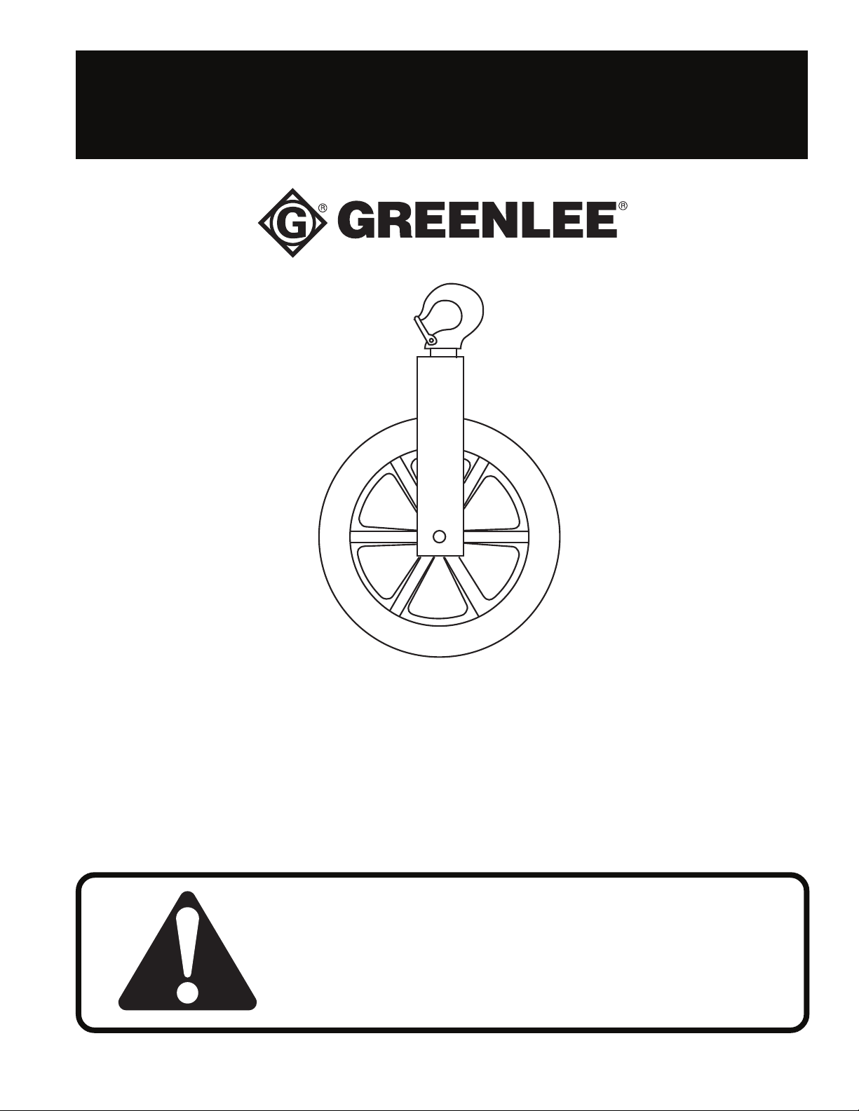
HOOK-TYPE CABLE SHEAVES
Read and understand this material before operating
or servicing this sheave. Failure to understand how
to safely operate this sheave could result in an
accident causing serious injury or death. This tool
should only be operated by qualified personnel.
999 2092.1
Find Quality Products Online at: [email protected]
www.GlobalTestSupply.com
©1996 Greenlee Textron Inc. IM 1260 REV 1 4/96
Page 2
8,000 lb. Capacity Hook-Type Cable Sheaves
Purpose of this Manual
Hook sheaves are used to change direction of the
pulling rope. This manual provides instructions of
rigging hook sheaves and calculating the load on the
sheave anchor point and supporting structures.
This manual should be kept available for operating and
maintenance personnel. For additional copies at no
charge, order IM-1260 (Part Number 999 2092.1).
DANGER
Immediate hazards which WILL result in severe
personal injury or death.
SAFETY ALERT SYMBOL
The symbol above is used to call your attention to
instructions concerning your personal safety. Watch
for this symbol. It points out important safety precautions. It means “ATTENTION! Become alert!
Your personal safety is involved!” Read the
message that follows and be alert to the possibility
of personal injury or death.
Read and understand all operating and safety instructions before using these sheaves.
Failure to properly set up and operate this system could result in an accident causing serious
injury or death. This product should only be used by personnel trained in its operation.
W ARNING
Hazards or unsafe practices which COULD result in
personal injury or death.
CAUTION
Hazards or unsafe practices which COULD result in
minor personal injury or property damage.
SA VE THESE INSTRUCTIONS
Additional copies of this manual and any decals on the product are available upon request at no charge.
Greenlee Textron Inc. / Subsidiary of Textron Inc.
Find Quality Products Online at: [email protected]
www.GlobalTestSupply.com
2
Page 3
8,000 lb. Capacity Hook-Type Cable Sheaves
SAFE OPERATING PRA CTICES
SA VE THESE INSTRUCTIONS
Calculating the Load on the Hook
• Use hook sheaves with a capacity rating
or greater than
developed by the puller. If you must use an
under-rated sheave
the pull force will not exceed the sheave rating,
or you must stop the pull if the force exceeds the
sheave rating.
• The load on the hook sheave may be twice
that on the rope. Know and understand how to
calculate each hook sheave load for each change
in rope direction.
• Make sure that all anchors, slings and
components of the supporting structure can
withstand the loads applied to them.
Failure to observe these warnings could result
in the hook sheave breaking its mounting and
striking nearby personnel, causing serious
injury or death.
that of the maximum force
, then you must know that
equal to
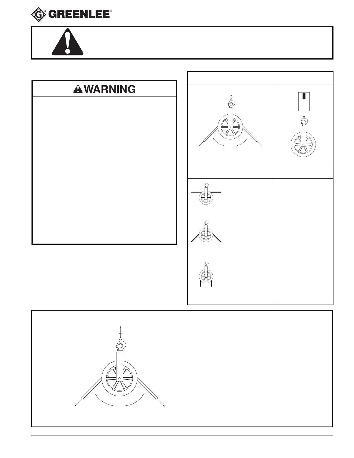
CHART #1
QUICK REFERENCE CHART
?
?
ADDED LOAD
ROPE ANGLE ON HOOK (R)
straight 0
150° .52 x T
135° .77 x T
120° 1 x T
90° 1.41 x T
60° 1.73 x T
FORMULA #1
45° 1.85 x T
30° 1.93 x T
full return 2 x T
T = Pulling Force
on Rope
LOAD ON HOOK
R
FORMULA FOR CALCULATING
HOOK AND STRUCTURE LOAD
(SINGLE HOOK SHEAVE)
θ = Degrees of change in rope direction
T = Rope Tension
R = Load on Hook and mounting
structure
Ø
T
DEGREES OF CHANGE IN ROPE
θ
DIRECTION
T
PULLING FORCE
ON ROPE
R = 2 x T x SIN ((180 - θ)/2)
Greenlee Textron Inc. / Subsidiary of Textron Inc.
Find Quality Products Online at: [email protected]
www.GlobalTestSupply.com
3
Page 4
8,000 lb. Capacity Hook-Type Cable Sheaves
SAFE OPERATING PRA CTICES
SA VE THESE INSTRUCTIONS
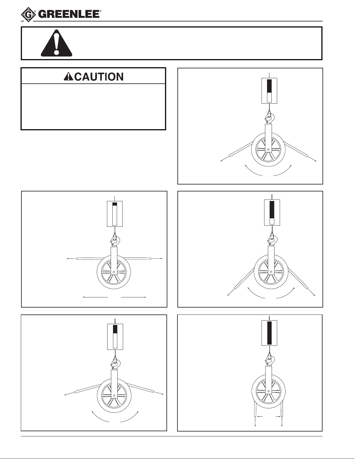
Check the angle the rope makes over
the sheave. Determine the load on the
hook and supporting structures, and be
sure they will withstand the load.
A rope making a 120°
bend over the sheave
adds the total pulling
force to the load on the
hook and structure.
120°
0
ADDS TOTAL
–
PULLING
1
–
FORCE
2
A straight rope will not
add any load to the
hook and structure.
A rope making a 150°
bend over the sheave
adds half the pulling
force to the load on the
hook and structure.
0°
0
–
1
–
2
0
–
1
–
2
NO LOAD
ADDED
ADDS 1/2
PULLING
FORCE
A rope making a 90°
bend over the sheave
adds nearly one and a
half times pulling force
to the load on the hook
and structure.
A rope making a full
return bend over the
sheave adds double
the total pulling force
to the load on the
hook and structure.
ADDS 1-1/2 x
0
–
PULLING
1
FORCE
–
2
90°
0
–
ADDS TWICE
1
–
PULLING
2
FORCE
180°
150°
Greenlee Textron Inc. / Subsidiary of Textron Inc.
Find Quality Products Online at: [email protected]
www.GlobalTestSupply.com
4
FULL
RETURN
Page 5
R1
ANGLE
C
ANGLE
A
8,000 lb. Capacity Hook-Type Cable Sheaves
SAFE OPERATING PRA CTICES
SA VE THESE INSTRUCTIONS
C
L
ANGLE
B
R2
ANGLE
D
T
CALCULATING THE LOAD ON
SINGLE HOOK SHEAVES
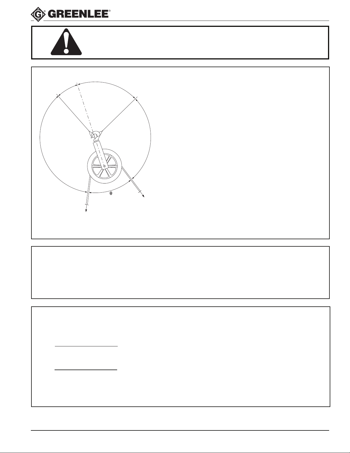
with two attachment points (Figure 2)
• Determine the load on the sheave from Chart #1
“Quick Reference Chart” or Formula #1 (page 3).
• Determine the angles “A” and “B” (Figure 2) by
extending an imaginary line beyond the yoke as
illustrated
OR
• Determine the angles “A” and “B” (Figure 2) by
measuring angles “C” and “D” and using Formula #2
below.
T
Figure 2 - Single Hook Sheave with two attachment points
FORMULA #2
FORMULA FOR CALCULATING ANGLES “A” AND “B”
Measure angles “C” and “D” (see Figure 2)
FORMULA #3
FORMULA FOR CALCULATING HOOKS AND STRUCTURES LOADS
(Twin Yoke Sheaves or Single Hook Sheaves with two attachment points)
WHERE:
R1 =
R
COS A + SIN A/TAN B
R = Added Load on Sheave (from page 3)
R1 = Load on left mounting
R2 = Load on right mounting
R2 =
COS B + SIN B/TAN A
R
θ = Degrees of change in rope direction
A = Degrees between left mounting line and centerline of rope legs
B = Degrees between right mounting line and centerline of rope legs
C
L = Centerline between rope legs
• Calculate the loads R1 and R2 using Formula #3 below
ANGLE A = 180° - 1/2
ANGLE B = 180° - 1/2
θ - C
θ - D
Greenlee Textron Inc. / Subsidiary of Textron Inc.
Find Quality Products Online at: [email protected]
www.GlobalTestSupply.com
5
Page 6
ANCHOR
#2
ANGLE B (45°)
8,000 lb. Capacity Hook-Type Cable Sheaves
8000 LBS.
ANGLE D (100°)
ANGLE θ (70°)
ANCHOR
#1
ANGLE A (35°)
ANGLE C (110°)
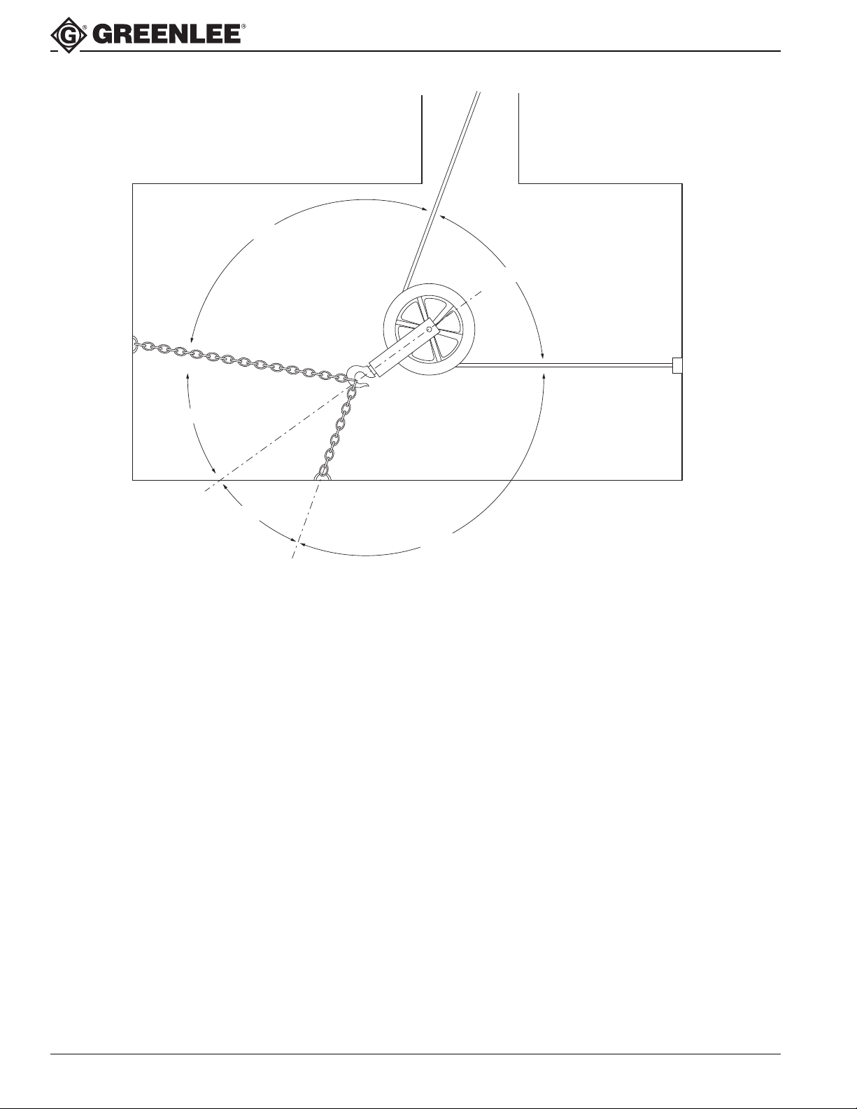
Example:
In this example we’ll pull up out of a manhole using the Ultra TuggerTM cable puller. The pull force is unknown so
we’ll assume the maximum rope tension will be 8000 pounds. First, we’ll need to measure some angles.
1. We measure angle θ between the rope legs as 70 degrees.
2. We measure angle A between the extended line of the frame and one anchor line either directly as 35 degrees
or by measuring angle C as 110 degrees and calculating angle A from Formula #2:
A = 180 - 1/2 x θ - C = 180 - 1/2 x 70 - 110 = 35 degrees
3. We measure angle B between the extended line of the frame and the second anchor line either directly as 45
degrees or by measuring angle D as 100 degrees and calculating angle B from Formula #2:
B - 180 - 1/2 x θ - D = 180 - 1/2 x 70 - 100 = 45 degrees
4. Calculate the hook load “R” from Formula #1:
R = 2 x T x sin((180-θ)/2) = 2 x 8000 x sin ((180-70)/20) = 16000 x sin(55) = 13106 pounds
5. Calculate the loads on anchor points 1 and 2 from Formula #3:
R1 = R/{cos(A) + sin(A) / tan(B)} = 13106 / {cos(35) + sin(35) / tan(45)} = 9410 pounds
R2 = R/{cos(B) + sin(B) / tan(A)} = 13106 / {cos(45) + sin(45) / tan(35)} = 7633 pounds
Summary:
Rope Tension: 8,000 lbs.
Load on Hook: 13,106 lbs.
Load on Chain 1 and Anchor 1: 9,410 lbs.
Load on Chain 2 and Anchor 2: 7,633 lbs.
Greenlee Textron Inc. / Subsidiary of Textron Inc.
Find Quality Products Online at: [email protected]
www.GlobalTestSupply.com
6
Page 7
8,000 lb. Capacity Hook-Type Cable Sheaves
REPRINTED WITH PERMISSION BY THE CROSBY GROUP
Crosby Hoist Hook
Warnings and Application Instructions
• Loads may disengage from hook if proper procedures are not followed.
• A falling load may cause serious injury or death.
• See OSHA Rule 1926.550(g) for personnel
hoisting by cranes or derricks. A Crosby 319, 320,
or 322 hook with a PL Latch attached (when
secured with the bolt, nut and pin) may be used
for lifting personnel.
• Threads may corrode and/or strip and drop the
load.
• Hook must always support the load. The load
must never be supported by the latch.
• Never apply more force than the hook’s assigned
Working Load Limit (WLL) rating.
• Read and understand these instructions before
using hook.
S-319
Important Safety Information - Read and Follow:
• Always visually inspect hook before using.
• Inspect hook and threads with magnetic particle
and/or dye penetrate annually, or more often in
severe operating conditions.
Note: Some Disassembly may be required.
• Never use a hook whose throat opening has been
increased, or whose tip has been bent more than 10
degrees out of plane from the hook body, or is in any
other way distorted or bent.
Note: A latch will not work properly on a hook with a
bent or worn tip.
S-320 S-322
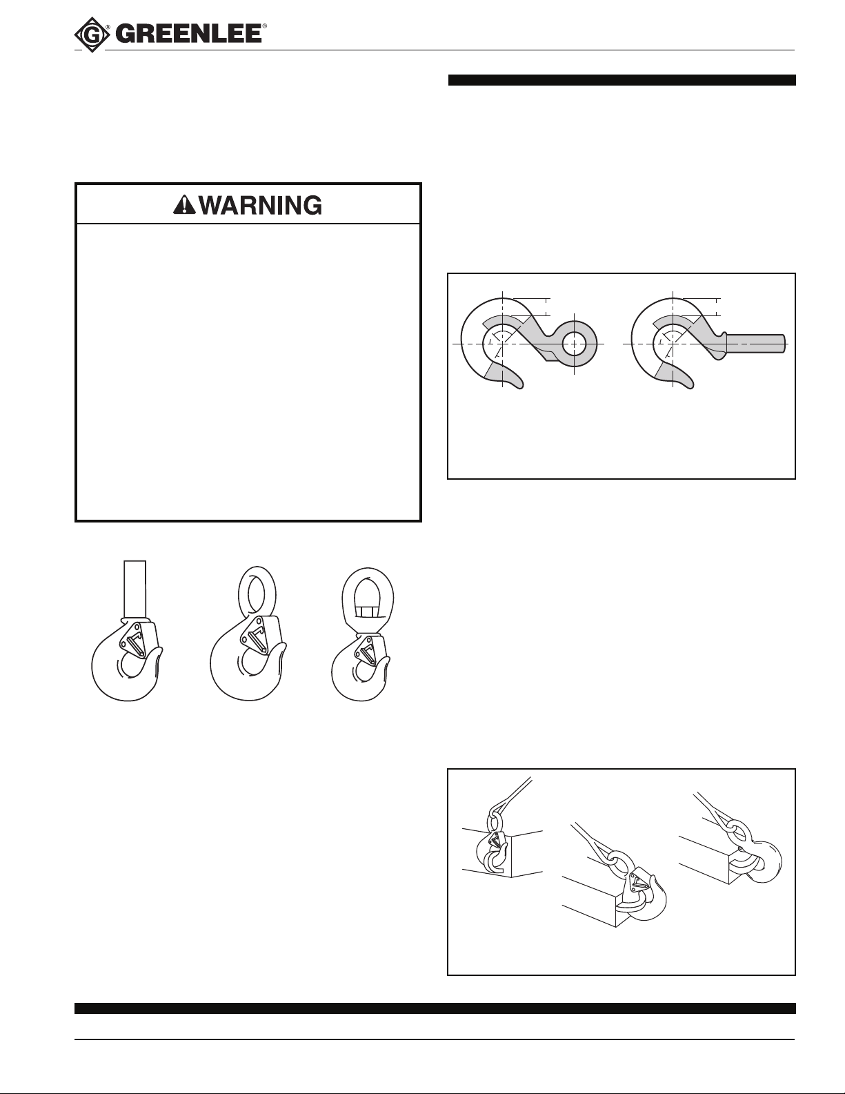
• Never use a hook that is worn beyond the limits
shown in Figure 1.
• Remove from service any hook with a crack, nick, or
gouge. Hooks with a crack, nick, or gouge shall be
repaired by grinding lengthwise, following the contour
of the hook, provided that the reduced dimension is
within the limits shown in Figure 1.
• Never repair, alter, rework, or reshape a hook by
welding, heating, burning, or bending.
2/3
45° 45°
ZONE B
60°
ZONE A
ZONE A: REPAIR NOT REQUIRED
ZONE B: 10% OF ORIGINAL DIMENSION
ZONE C: 5% OF ORIGINAL DIMENSION
ZONE D: SEE MINIMUM THREAD SIZE CHART
ZONE C
Figure 1
ZONE B
45° 45°
60°
ZONE A
ZONE C
2/3
ZONE D
• Never side load, back load, or tip load a hook.
(See Figure 2.)
• Eye hooks, shank hooks and swivel hooks are
designed to be used with wire rope or chain.
Efficiency of assembly may be reduced when used
with synthetic material.
• Do not swivel the S-322 swivel hook while it is
supporting a load.
• The use of a latch may be mandatory by regulations
or safety codes; e.g., OSHA, MSHA, ANSI/ASME
B30, Insurance, etc.
Note: When using latches, see instructions in
“Understanding: The Crosby Group Warnings”
for further information.
Side Load
Back Load
Wrong
Figure 2
Tip Load
Greenlee Textron Inc. / Subsidiary of Textron Inc.
Find Quality Products Online at: [email protected]
www.GlobalTestSupply.com
7
Page 8
8,000 lb. Capacity Hook-Type Cable Sheaves
LOAD
LOAD
REPRINTED WITH PERMISSION BY THE CROSBY GROUP
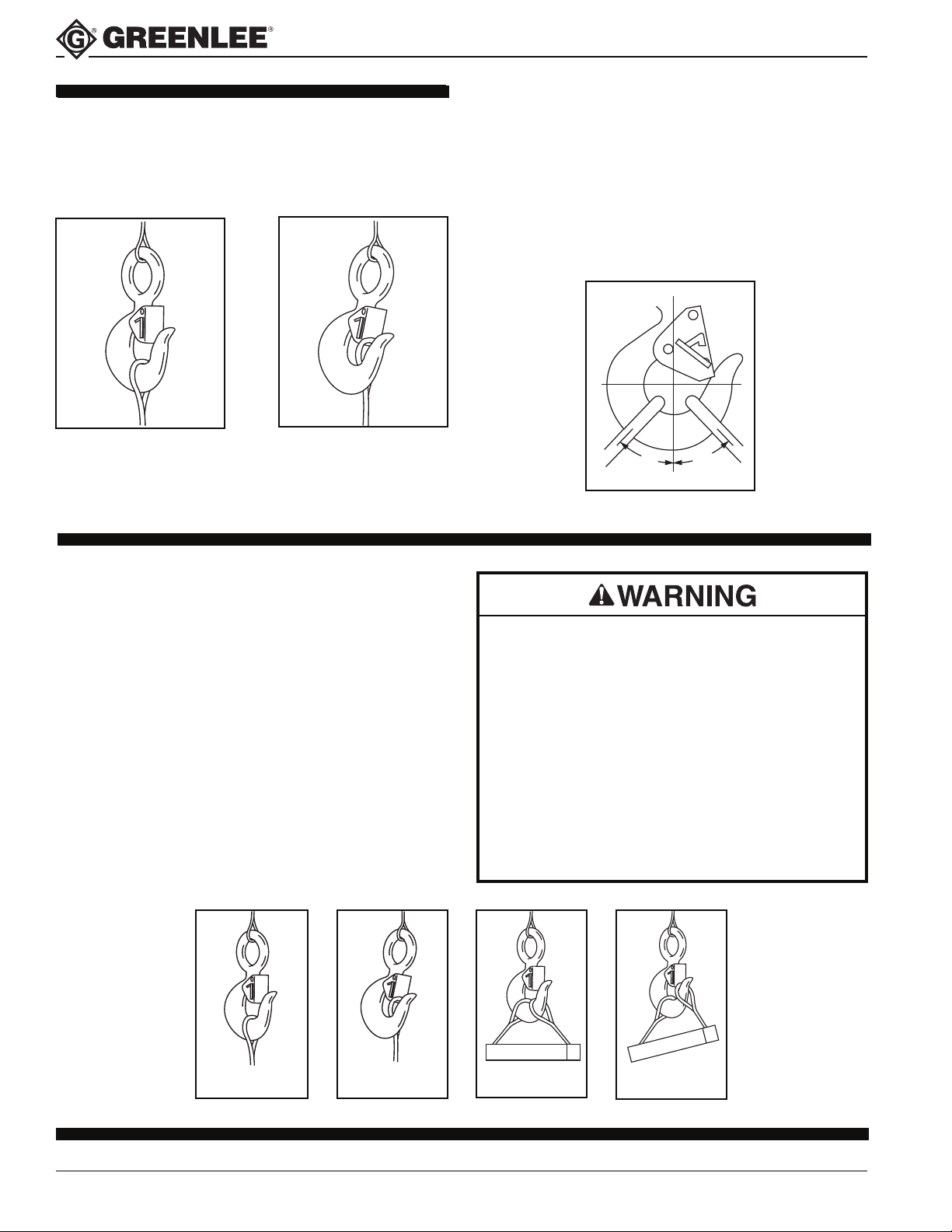
• Always make sure the hook supports the load.
(See Figure 3.) The latch must never support the load
(See Figure 4).
Right
Figure 3
Wrong
Figure 4
Warnings and Application Instructions
• When placing two (2) sling legs in hook, make sure
the angle from the vertical to the outermost leg is not
greater than 45°, and the included angle between the
legs does not exceed 90° (See Figure 5).
• See ANSI/ASME B30.1 0 “Hooks” for additional
information.
*For angles greater than 90°, or more than two (2) legs, a master link
or bolt-type anchor shackle should be used to attach the legs of the
sling to the hook.
45° 45°
Figure 5
Important Safety Information - Read and Follow:
• Always inspect hook and latch before using.
• Never use a latch that is distorted or bent.
• Always make sure spring will force the latch against
the tip of the hook.
• Always make sure hook supports the load. The latch
must never support the load. (See Figures 1 & 2.)
• When placing two (2) sling legs in hook, make sure
the angle between legs is small enough and the legs
are not tilted so that nothing bears against the bottom
of the latch. (See Figures 3 & 4.)
• Latches are intended to retain loose sling or devices
under slack conditions.
• Latches are not intended to be an anti-fouling device.
• Loads may disengage from hook if proper procedures are not followed.
• A falling load may cause serious injury or death.
• See OSHA Rule 1926.550(g) for personnel
hoisting by cranes or derricks. A Crosby or
McKissick hook and this latch (when secured with
the bolt, nut and pin) may be used for lifting
personnel.
• Hook must always support the load. The load
must never be supported by the latch.
• Read and understand these instructions before
using hook.
Right
Figure 1
Greenlee Textron Inc. / Subsidiary of Textron Inc.
Find Quality Products Online at: [email protected]
www.GlobalTestSupply.com
Wrong
Figure 2
8
Right
Figure 3
Wrong
Figure 4
Page 9
8,000 lb. Capacity Hook-Type Cable Sheaves
7
1
5
3
4
6
6
2
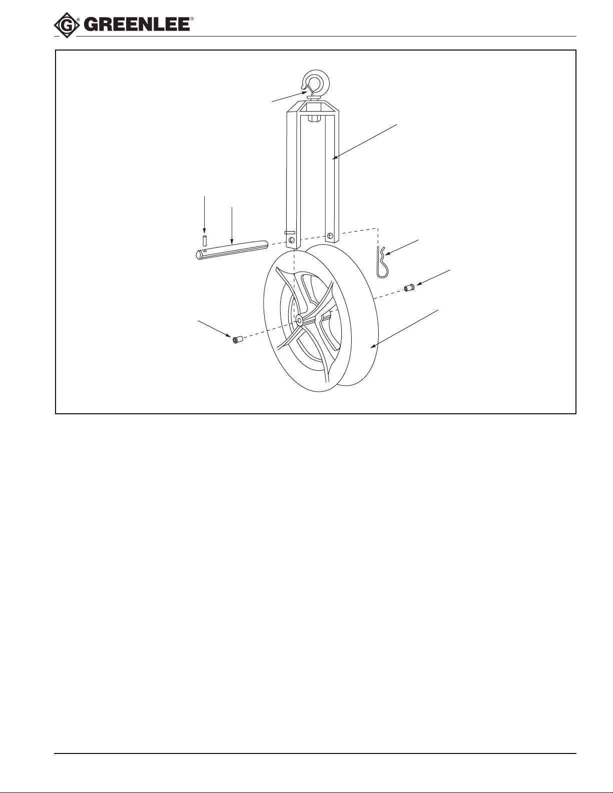
Parts List
KEY PART NO. PART NO. PART NO.
NO. DESCRIPTION QTY. FOR 8012 FOR 8018 FOR 8024
1 Frame Unit 1 500 0854.4 500 0855.2 500 0856.0
2 Sheave Unit (with #6) 1 500 0843.9 500 0844.7 500 0845.5
3 Sheave Pin 1 500 0838.2 500 0846.3 500 0850.1
4 #8 Hitch Pin Clip 1 905 0302.3 905 0302.3 905 0302.3
Decal 1 501 2121.9 501.2121.9 501 2121.9
5 Roll Pin, 3/16 x 1.50 1 905 0700.2 905 0700.2 905 0700.2
6 Bearing 2 905 4838.8 905 4838.8 905 4838.8
7 Latch Unit 1 905 4185.5 905 4185.5 905 4185.5
Greenlee Textron Inc. / Subsidiary of Textron Inc.
Find Quality Products Online at: [email protected]
www.GlobalTestSupply.com
9
 Loading...