

Page 1
INSTRUCTION MANUAL
773 and 774
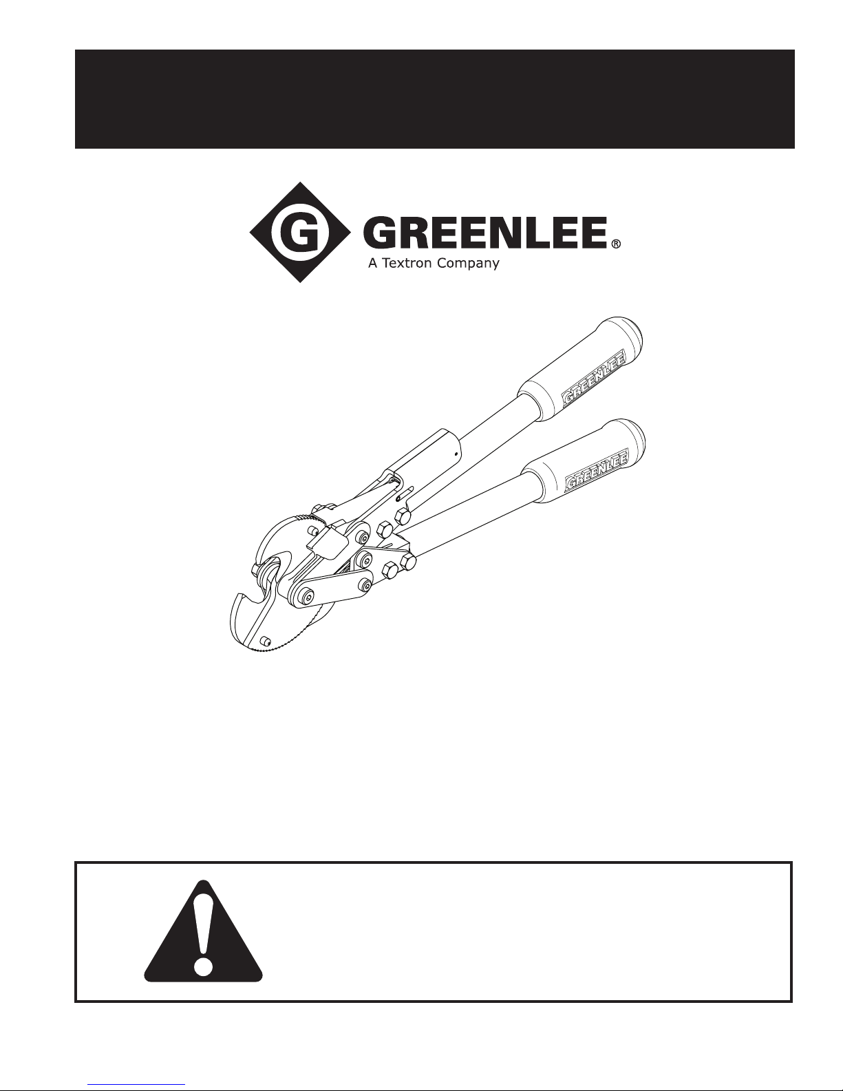
Ratchet Cable Cutters
99947285 REV 5 © 2007 Greenlee Textron Inc. 2/07
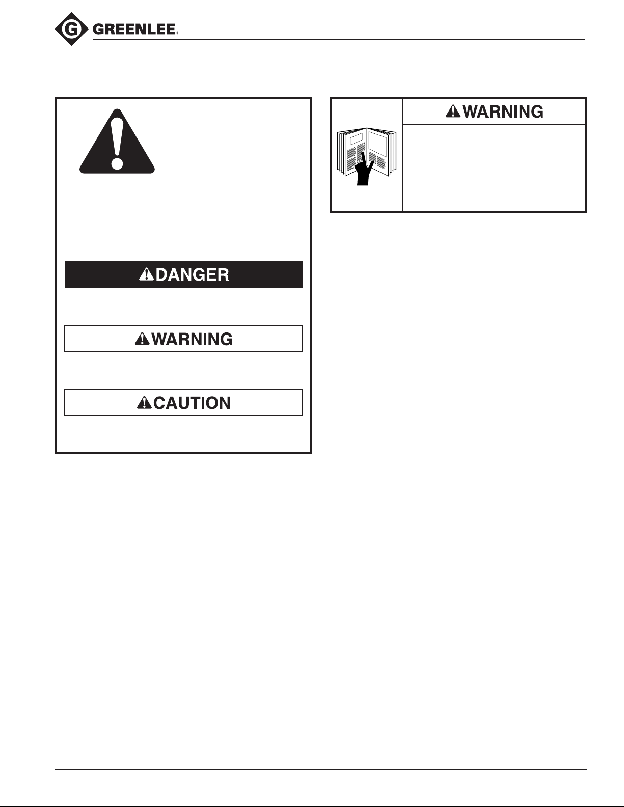
Read and understand all of the instructions and
safety information in this manual before operating
or servicing this tool.
Page 2

773 and 774 Ratchet Cable Cutters
Table of Contents
Description ..................................................................... 2
Purpose of this Manual .................................................. 2
Important Safety Instructions ......................................3-4
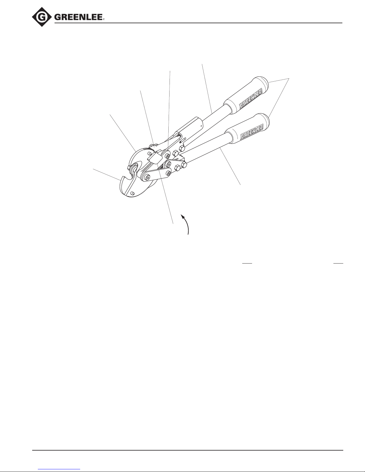
Identication ................................................................... 5
Specications ................................................................. 5
Operation ........................................................................ 6
Maintenance
General ..................................................................... 7
Cleaning the cutter ................................................... 7
Lubricating the cutter ............................................... 7
Disassembly ................................................................... 8
Assembly ...................................................................9-11
Illustration ..................................................................... 12
Parts List .................................................................13-14
Description
Greenlee 773 and 774 Ratchet Cable Cutters are
non-insulated cutting tools intended for use on copper
and standard aluminum electrical cable. The 773 will
accommodate up to 500 Kcmil copper or 795 Kcmil
aluminum cable. The 774 will cut up to 750 Kcmil
copper or 795 Kcmil aluminum cable.
Both cable cutters ratchet and are equipped with berglass handles and rubber grips to limit operator fatigue.
They are not intended for use on ACSR (aluminum
cable, steel-reinforced) cable.
The Greenlee 773 and 774 Ratchet Cable Cutters are
protected by U.S. Patent No. 6,766,581.
Safety
Safety is essential in the use and maintenance of
Greenlee tools and equipment. This instruction manual
and any markings on the tool provide information for
avoiding hazards and unsafe practices related to the
use of this tool. Observe all of the safety information
provided.
Purpose of this Manual
This instruction manual is intended to familiarize
personnel with the safe operation and maintenance
procedures for the Greenlee 773 and 774 Cable Cutters.
Keep this manual available to all personnel.
Replacement manuals are available upon request
at no charge at www.greenlee.com.
Greenlee / A Textron Company 2 4455 Boeing Dr. • Rockford, IL 61109-2988 USA • 815-397-7070
All specications are nominal and may change as design improvements occur. Greenlee Textron Inc. shall not be liable for damages
resulting from misapplication or misuse of its products.
Molykote is a registered trademark of Dow Corning Corporation.
Loctite is a registered trademark of Loctite Corporation.
KEEP THIS MANUAL
Page 3
IMPORTANT SAFETY INFORMATION
SAFETY
ALERT
SYMBOL
This symbol is used to call your attention to
hazards or unsafe practices which could result in
an injury or property damage. The signal word,
dened below, indicates the severity of the hazard.
The message after the signal word provides information for preventing or avoiding the hazard.
Immediate hazards which, if not avoided, WILL
result in severe injury or death.
773 and 774 Ratchet Cable Cutters
Read and understand all of the
instructions and safety information
in this manual before operating or
servicing this tool.
Failure to observe this warning could
result in severe injury or death.
Hazards which, if not avoided, COULD result in
severe injury or death.
Hazards or unsafe practices which, if not avoided,
MAY result in injury or property damage.
Greenlee / A Textron Company 3 4455 Boeing Dr. • Rockford, IL 61109-2988 USA • 815-397-7070
Page 4
773 and 774 Ratchet Cable Cutters
IMPORTANT SAFETY INFORMATION
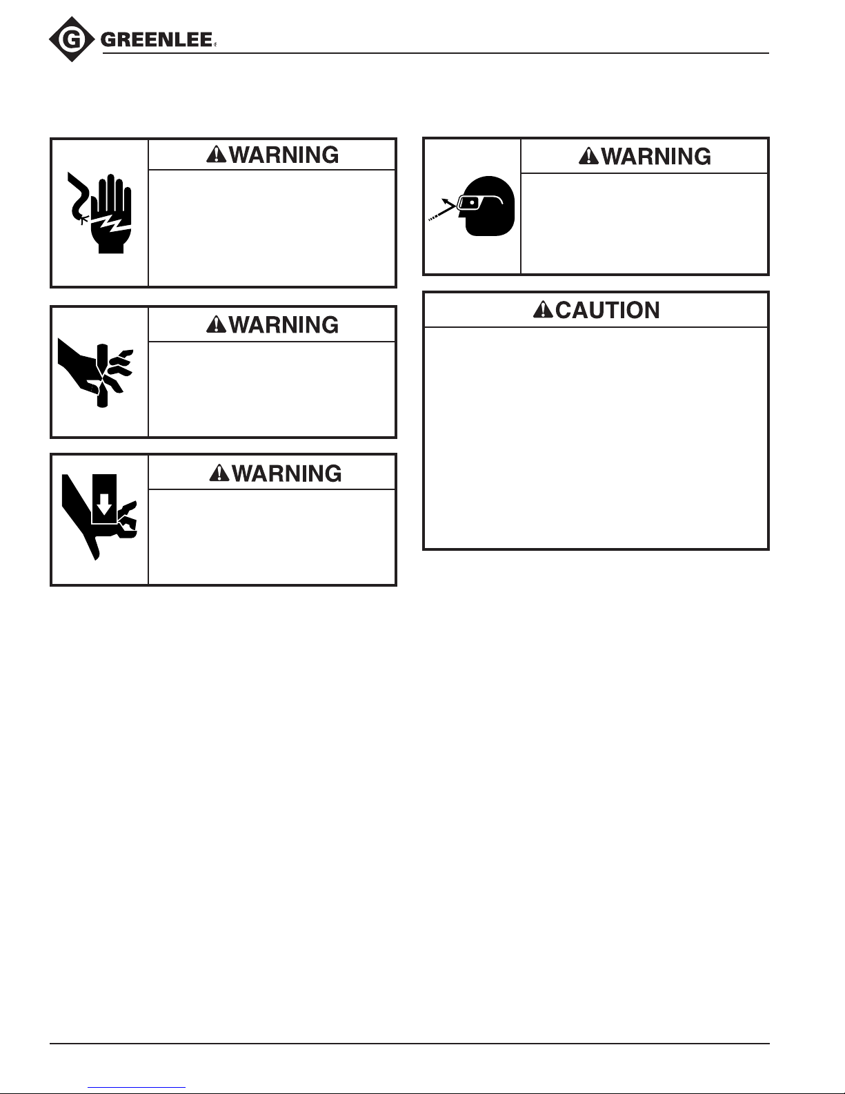
Electric shock hazard:
This tool is not insulated. Do not use
this tool near energized electrical
lines.
Failure to observe this warning could
result in severe injury or death.
Keep hands away from closing
blades.
Pinch points:
Keep hands away from moving
parts.
•
This tool is intended for two-handed operation.
Maintain a rm grip on both handles during
operation.
• Do not cut ACSR or steel.
• Do not exceed the rated capacity of this tool.
• Inspect before use. Replace any worn or
damaged parts.
• Do not perform any service or maintenance other
than as described in this manual.
Failure to observe these precautions may result in
injury or property damage.
Wear eye protection when using this
tool. Failure to wear eye protection
could result in serious eye injury
from ying debris.
Greenlee / A Textron Company 4 4455 Boeing Dr. • Rockford, IL 61109-2988 USA • 815-397-7070
Page 5
Identification
Stationary
blade
Movable
blade
Speed
Pawl
Link
Movable
handle
Grips
Stationary
handle
Release
knob
773 and 774 Ratchet Cable Cutters
Specifications
773 774
Mass/Weight ........................................................................................ 2.4 kg (5.3 lb) .............................. 2.6 kg (5.8 lb)
Length................................................................................................394 mm (15.5") ..........................486 mm (19.125")
Width
at blades ..................................................................................127 mm (5.0") ...............................127 mm (5.0")
at handles ..............................................................................132 mm (5.19") ..................................152 mm (6")
Thickness ............................................................................................68.5 mm (2.7") ...............................68.5 mm (2.7")
Jaw opening (minimum) .....................................................................30 mm (1.188") ..............................30 mm (1.188")
Handle force at Maximum Copper Capacity ...........................................289 N (65 lb) ..................................267 N (60 lb)
Maximum-Rated Capacity
Copper (600-Volt Building Wire) ................................................ 240 mm2 (500 Kcmil) ..................... 400 mm2 (750 Kcmil)
Aluminum (600-Volt Building Wire) ............................................400 mm2 (795 Kcmil) ..................... 400 mm2 (795 Kcmil)
Communications Cable ............................................................. 30 mm (1.188") O.D. ..................... 30 mm (1.188") O.D.
Frequent Use
Copper (600-Volt Building Wire) ................................................ 150 mm2 (350 Kcmil) ..................... 240 mm2 (500 Kcmil)
Aluminum (600-Volt Building Wire) ............................................400 mm2 (750 Kcmil) ..................... 400 mm2 (750 Kcmil)
Communications Cable ............................................................. 30 mm (1.188") O.D. ..................... 30 mm (1.188") O.D.
Greenlee / A Textron Company 5 4455 Boeing Dr. • Rockford, IL 61109-2988 USA • 815-397-7070
Page 6
Operation
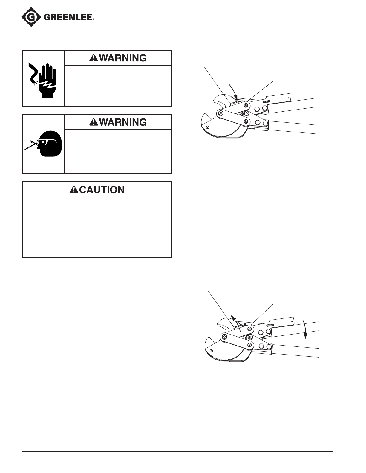
release knob
engage
link
release knob
disengage
link
773 and 774 Ratchet Cable Cutters
Electric shock hazard:
This is not an insulated tool.
Contact with live circuits could
result in severe injury or death.
Wear eye protection when using this
tool. Failure to wear eye protection
could result in serious eye injury
from ying debris.
• This tool is intended for two-handed operation.
Maintain a rm grip on both handles when using
this tool.
• Inspect before use. Replace any worn or
damaged parts.
Failure to observe these precautions may result in
injury or property damage.
1. Check to see that the release knob is against the link.
2. Place the cable to be cut between the cutting
blades.
3. Open and close the handles until the cable is cut.
Note: The automatic rapid advance mechanism will
advance the movable blade by 3 teeth each time
the handle is opened. The blade advances 1 tooth
for each closing of the handle. The rapid advance
mechanism is spring loaded to disengage when
maximum leverage is needed to cut the cable.
4. When the cut is complete, the automatic blade
mechanism automatically returns the blade to the
open position and resets the reverse lever to cut
cable.
Note: To open the blade before the cut is complete,
move the release knob away from the link and press
the handles together. The blade spring will return the
Greenlee / A Textron Company 6 4455 Boeing Dr. • Rockford, IL 61109-2988 USA • 815-397-7070
Page 7
Maintenance
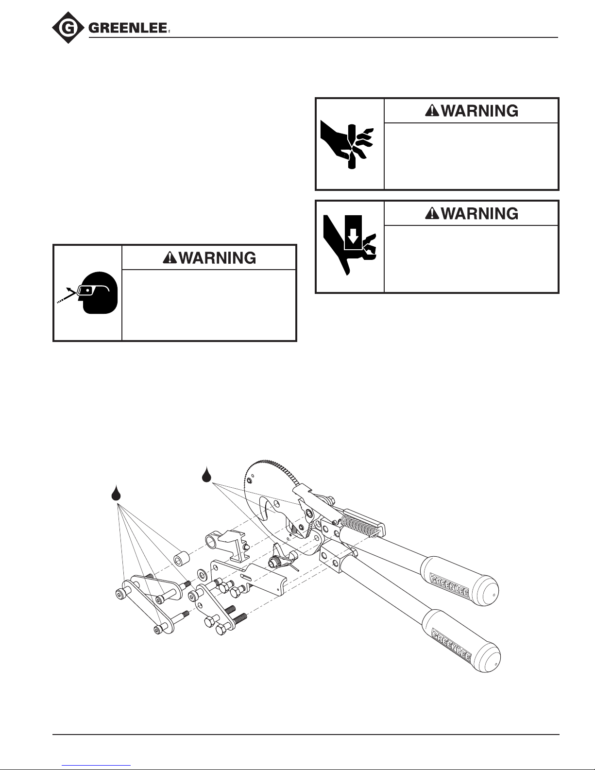
Lubrication points
—use Molykote
®
773 and 774 Ratchet Cable Cutters
General
Maintain the tool with care. Keep the blades sharp
and the tool clean for better and safer performance.
Follow instructions for lubricating the cutter; lubrication
prolongs the tool life and enables the tool to cut with
less force. Keep grips dry, clean and free from oil and
grease.
Note: The blade pivot lock nut (23) may require tightening after making several initial cuts on a new or repaired
unit. Always maintain proper adjustment on all pivot
screws. For adjustment procedures, see Assembly—
Tighten pivot screws.
Cleaning the cutter
Wear eye protection when using this
tool. Failure to wear eye protection
could result in serious eye injury
from ying debris.
Blow dirt and/or cable particles out of the ratchet
mechanism with compressed air.
Lubricating the cutter
Keep hands away from closing
blades.
Pinch points:
Keep hands away from moving
parts.
Close the blades and apply Molykote lubricant or
equivalent between the blades. Lubricate the teeth on
holding pawl (6) and drive pawl (7). Lubricate the four
pivot shoulder screws (13, 16 and 17) and area between
pivoting surfaces. Operate the cutter to spread the
lubricant.
Disassemble, clean, and lubricate the tool if it does not
operate smoothly.
Greenlee / A Textron Company 7 4455 Boeing Dr. • Rockford, IL 61109-2988 USA • 815-397-7070
Page 8
Disassembly
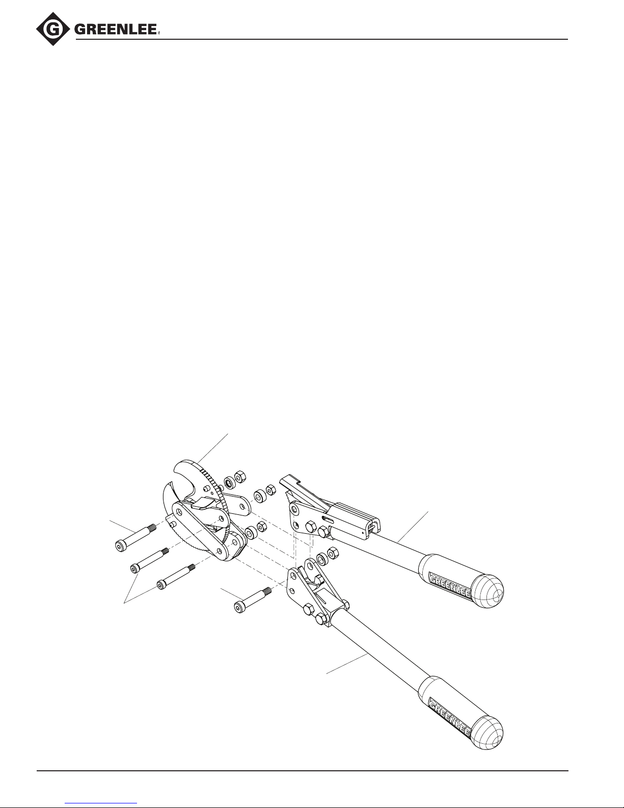
cutter head
assembly
movable handle
assembly
stationary handle
assembly
17
16
13
773 and 774 Ratchet Cable Cutters
This tool consists of three subassemblies: the cutter
head, stationary handle, and movable handle subassemblies (see gure).
1. Cutter head assembly: movable blade (1), stationary
blade (2), release lever (3), links (4), spring cover
(10), reverse lever pin (12), spring (37), bushing (29),
return spring (36), shoulder screw (17) and related
hardware.
2. Stationary handle assembly: handle unit (39), handle
plates (5), holding pawl (6), torsion spring (40),
shoulder screw (16) and related hardware.
3. Movable handle assembly: handle unit (38), handle
plates (8 and 9), speed pawl (11), spring (35), drive
pawl (7), shoulder screws (13 and 16) and related
hardware.
The disassembly procedure is divided into sections of
the tool. Disassemble only the section(s) necessary to
complete the repair.
Disassemble the tool on a at, clean surface. Take care
not to lose or damage any parts that may fall free during
disassembly.
Cutter head
1. Open the movable blade to release tension on the
blade return spring (36).
2. Remove two shoulder screws (16) and remove the
cutter head assembly from the handle assemblies.
Note: Holding pawl (6), torsion spring (40), drive
pawl unit (7), washer (22) and spacer (19) may fall
free during disassembly.
3. Remove shoulder screw (17), spacers (27 and 20),
links (4), release lever (3) and bushing (29).
4. Remove screw (15) and separate cover (10) from
stationary blade (2).
5. Remove screw (41) and spring (36).
Stationary handle
6. Remove shoulder screw (13) and movable handle
assembly.
7. Remove two screws (30) and stationary handle
plates (5).
Movable handle
8. Remove two screws (31), left handle plate (8), right
handle plate (9), speed pawl (11) and spring (35).
Greenlee / A Textron Company 8 4455 Boeing Dr. • Rockford, IL 61109-2988 USA • 815-397-7070
Page 9
Assembly
slot
chamfer
38
9
4
27
23
15
10
25
2
36
41
14
20
17
4
29
3
1
32
Apply Loctite 680
Apply Loctite 242
Apply Loctite 271
46
(optional)
13
16
30
5
39
11
33
31
8
35
34
38
9
.20"
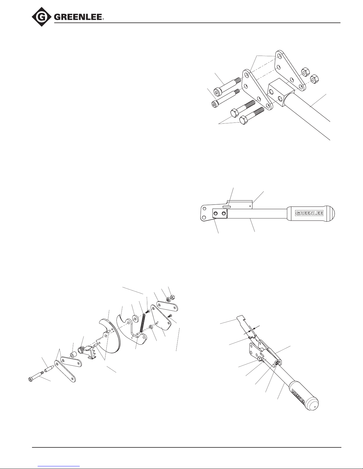
Refer to the Exploded View and Parts List for correct
orientation and placement of parts.
any worn or damaged parts. Wherever
results in metal-to-metal contact, coat the surfaces with
Molykote or equivalent lubricant.
Cutter head
1. Apply Loctite 680 retaining compound to two dowel
pins (32) and install into movable blade, if necessary.
The dowel pins should be ush with the at side of
the blade. Remove excess Loctite.
2. Apply Loctite 271 thread adhesive to screw (41)
and install screw through end of spring (36) and into
movable blade. Adjust until end of screw is ush
with the angled side of the blade. Allow Loctite to
cure for 10 minutes and remove excess adhesive.
3. Install roll pin (14) into stationary blade (2), if
necessary.
4. Install end of spring (36) over roll pin (14) and
assemble spacer (25), and cover (10). Apply Loctite
242 thread adhesive to screw (15) and assemble
to stationary blade (2). Roll pin (14) should be ush
with top of cover (10).
5.
Install optional screw guide (46) onto shoulder screw
(17) to help guide the screw through components.
6. Lubricate components and assemble shoulder
screw (17), two links (4), bushing (29), reverse lever
(3), movable blade (1), stationary blade (2), spacer
(20), cover (10), link (4), spacer (27)—with counterbore toward link. Remove optional guide (46) if used
and install lock nut (23). Tighten lock nut so gap
between blades does not exceed .004 inches.
Inspect and replace
the assembly
773 and 774 Ratchet Cable Cutters
Movable handle
9. Assemble right and left handle plates (8 and 9) to
handle unit (38), but do not tighten hex screws (31).
Orient handle plates so slotted hole is opposite the
chamfer in the handle adapter.
10. Install roll pin (34) into right and left handle plates.
11. Install roll pin (33) into speed pawl (11), if necessary.
The roll pin should protrude .20 inches from each
side of the speed pawl.
12. Install spring (35) between handle plates.
13. Spread the right and left handle plates and install
speed pawl so the roll pin ts into the slot in the
handle
plates. Use the speed pawl to compress
spring (35).
Stationary handle
7. Assemble handle plates (5) to handle unit (39),
but do not tighten hex screws (30).
8. Insert shoulder screws (13 and 16) to align handle
plates (5) and tighten hex screws (30) to 170-190
in-lb. Remove shoulder screws.
Greenlee / A Textron Company 9 4455 Boeing Dr. • Rockford, IL 61109-2988 USA • 815-397-7070
14. Insert shoulder screws (13 and 16) to align handle
plates and tighten hex screws (31) to 170-190 in-lb.
Remove shoulder screws.
Page 10
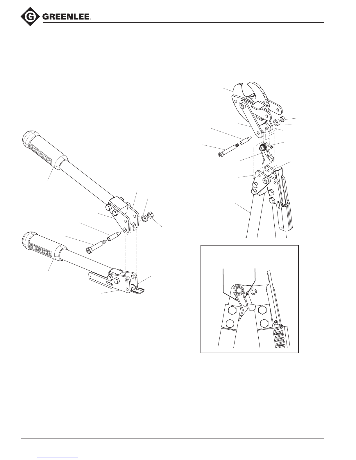
Assembly (cont’d)
2
4
40
5
39
5
6
10
19
24
47
(optional)
16
Note:
Ends of torsion spring should be
against handle and pawl as shown.
5
26
23
5
stationary handle
assembly
9
movable handle
assembly
8
46
(optional)
13
773 and 774 Ratchet Cable Cutters
Movable handle to stationary handle
15. Install movable handle assembly between the
stationary handle plates and align the 3/8" pivot
holes.
16.
Install optional screw guide (46) onto shoulder screw
(13) to help guide the screw through components.
17. Lubricate shoulder screw (13) and install it through
the handle plates (5 and 8), handle plates (9 and
5) and spacer (26). Remove guide (46) if used and
install lock nut (23).
Cutter head to stationary handle
18. Install torsion spring (40) onto holding pawl (6)
and locate them between the handle plates on the
stationary handle (39) as shown.
Greenlee / A Textron Company 10 4455 Boeing Dr. • Rockford, IL 61109-2988 USA • 815-397-7070
19. Install head assembly between handle plates on the
stationary handle and around the holding pawl (6).
20. Install optional screw guide (47) onto shoulder screw
(16) to help guide the screw through components.
21. Lubricate shoulder screw (16) and install it through
link (4), handle plate (5), torsion spring (40), holding
pawl (6), stationary blade (2), second handle plate (5),
cover (10) and spacer (19). Remove guide (47)
if used and thread on lock nut (24), but do not
tighten.
Page 11
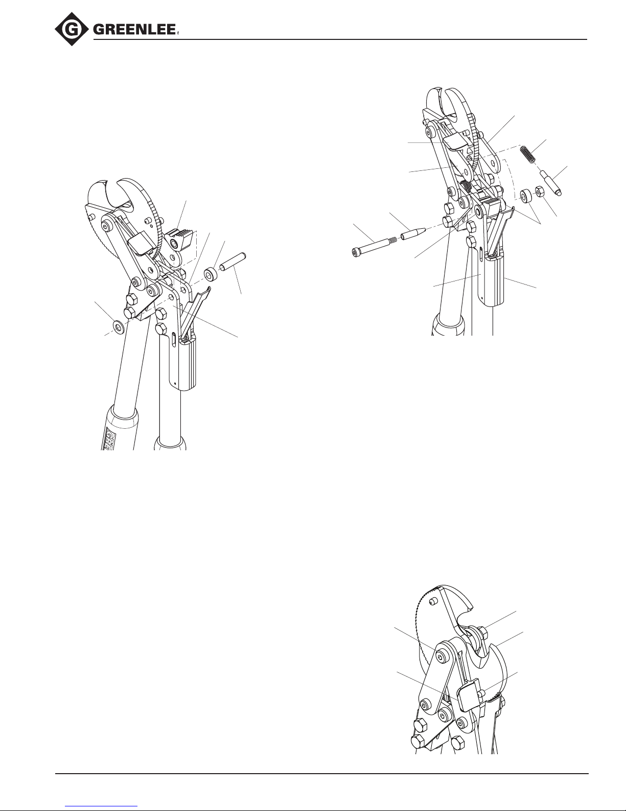
Assembly (cont’d)
8
7
9
19
5/16 x 1-1/4 pin
22
3
4
22
8
4
37
12
24
19
9
16
47
(optional)
17
3
23
1
32
Cutter head to movable handle
22. Lubricate the ID and teeth on drive pawl unit (7).
Install drive pawl unit between right and left handle
plate (8 and 9) with teeth toward speed pawl. Install
a 5/16 x 1-1/4" pin through the handle plates, pawl
unit, washer (22) and spacer (19) to keep it in place.
773 and 774 Ratchet Cable Cutters
23. Lubricate release lever pin (12) OD and spherical
end. Install spring (37) and release lever pin (12) into
release lever (3).
24. Rotate cutter head to align 5/16" diameter holes in
links (4) with handle plates (8 and 9).
Note: Spherical end of release lever pin should nest
into one of the two pockets in drive pawl unit.
25.
Install optional screw guide (47) onto shoulder screw
(16) to help guide the screw through components.
26.
Lubricate components and install shoulder screw (16)
through link (4), washer (22), right handle plate (8),
drive pawl unit (7), left handle plate (9), spacer (19),
link (4) and spacer (19). Remove guide (47) if used
and thread on lock nut (24), but do not tighten.
Tighten pivot screws
27. Tighten lock nut (23) on shoulder screw (17) so
gap between blades does not exceed .004 inches.
Spring (36) must open movable blade freely.
28.
Tighten lock nuts on three shoulder screws (13 and 16)
and adjust until components pivot freely.
29. Operate the cutter without cutting cable (see
Operation) and check for proper function. At the
end of the cutting cycle, the spring (36) should
automatically return the movable blade (1) to the
fully open position. Pin (32) should hit and reset
reverse lever (3) into the cutting position. Pin (32)
should remain against the reverse lever as shown.
Note: Tighten the lock nut (23) on screw (17) if there
is a gap between the pin and reverse lever. Loosen
the lock nut (23) if the movable blade returns slowly
or the reverse lever does not reset to the cutting
position.
Greenlee / A Textron Company 11 4455 Boeing Dr. • Rockford, IL 61109-2988 USA • 815-397-7070
Page 12
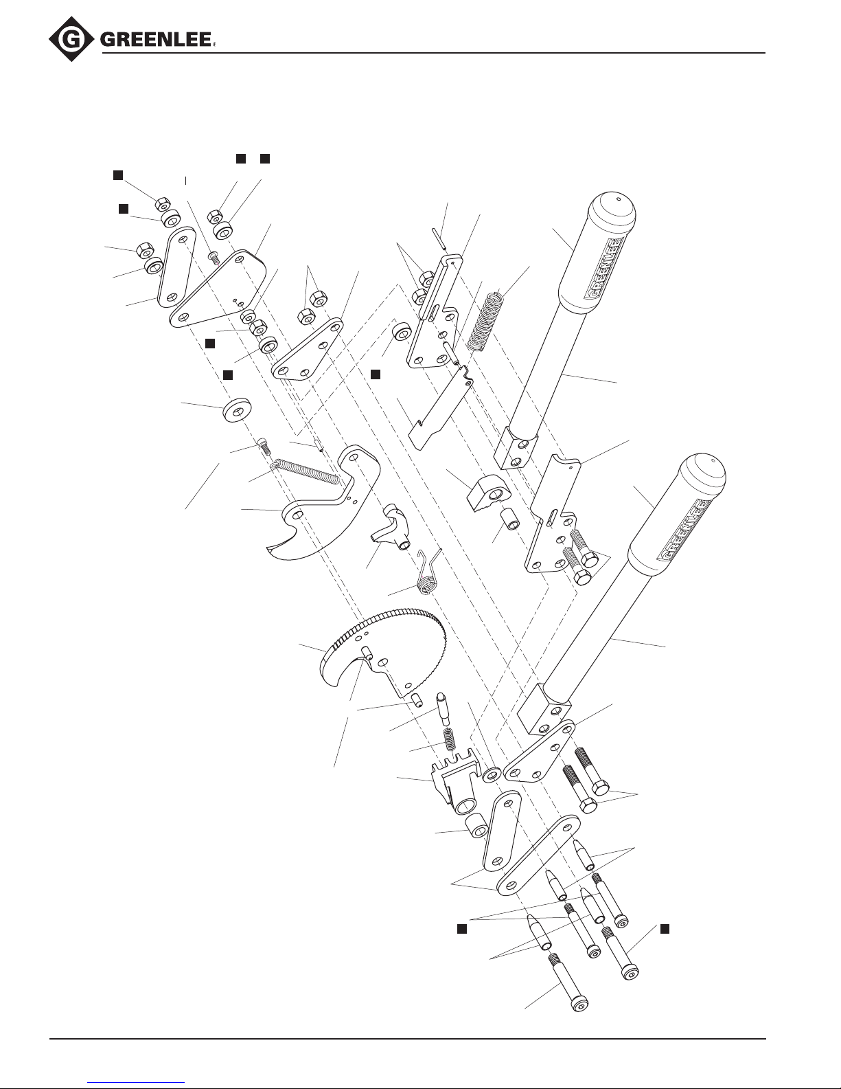
Illustration
34
32
Apply Loctite 680
Retaining Compound
Apply
Loctite 271
Apply
Loctite 242
21
42
7
14
19
24
15
1
2
3
4
4
5
6
8
9
11
12
19
20
22
23
25
26
29
30
31
35
36
37
21
40
41
10
24
19
27
23
23
23
5
39
38
33
17
13
46
(optional)
16
47
(optional)
773 and 774 Ratchet Cable Cutters
Greenlee / A Textron Company 12 4455 Boeing Dr. • Rockford, IL 61109-2988 USA • 815-397-7070
Page 13

Parts List
773 and 774 Ratchet Cable Cutters
773 774
Key Part No. Part No. Description Qty
1 Blade assembly, movable (includes key 32) ........... 1
2 Blade, stationary .................................................... 1
3 50105213 50105213 Lever, release ......................................................... 1
4 50105248 50105248 Link ......................................................................... 3
5 50105264 50105264 Plate, stationary handle .......................................... 2
6 50105280 50105280 Pawl, holding .......................................................... 1
7 50106317 50106317 Pawl unit, drive (includes key 42) ........................... 1
8 50105310 50105310 Plate, right handle .................................................. 1
9 50105337 50105337 Plate, left handle ..................................................... 1
10 50106775 50106350 Cover, spring .......................................................... 1
11 50105370 50105370 Pawl, speed ............................................................ 1
12 50106252 50106252 Pin, reverse lever .................................................... 1
13 90553764 90553764 Screw, shoulder, 3/8" x 1.50" x 5/16-18 ................ 1
14 90513479 90513479 Rollpin, .125" x .50" ............................................... 1
15 90501110 90501110 Screw, cap, #10-24 x .50" button head ................. 1
16 F023194 F023194 Screw, shoulder, 5/16" x 1.75 x 1/4-20 .................. 2
17 90552229 90552229 Screw, shoulder, 3/8" x 1.75 x 5/16-18 .................. 1
19 50106279 50106279 Spacer, .315" x .62" x .286" ................................... 3
20 50106287 50106287 Spacer, main pivot.................................................. 1
21 50223003 50223003 Grip, rubber 0.995" x 1.50" x 5.09" ........................ 2
22 90516567 90516567 Washer, 5/16 at..................................................... 1
23 F009550 F009550 Nut, locking, 5/16-18.............................................. 6
24 90541200 90541200 Nut, locking, 1/4-20................................................ 2
25 50018671 50018671 Spacer, .203" x .50" x .179" ................................... 1
26 50018663 50018663 Spacer, .377" x .62" x .230" ................................... 1
27 50109901 50109901 Spacer, .377" x .62" x .187" ................................... 1
29 50106295 50106295 Bushing .................................................................. 1
30 90553853 90553853 Screw, cap, 5/16-18 x 1.75" hex head ................... 2
31 90552652 90552652 Screw, cap, 5/16-18 x 1.25" hex head ................... 2
32 Pin, dowel, .2503" x .50" ........................................ 2
33 90506995 90506995 Rollpin, .187" x 1" .................................................. 1
34 90517822 90517822 Rollpin, .094" x 1" .................................................. 1
35 90553780 90553780 Spring, compression .............................................. 1
36 90539850 90539850 Spring, extension ................................................... 1
37 90553802 90553802 Spring, compression .............................................. 1
38 50106651 50106716 Handle kit—one handle and hardware
(includes keys 21, 31, 23) ....................................... 1
39 50106660 50106724 Handle kit—one handle and hardware
(includes keys 21, 30, 23) ....................................... 1
40 50106309 50106309 Spring, torsion ........................................................ 1
41 F017344 F017344 Screw, cap, #10-24 x 1/2, socket head ................. 1
42 90553799 90553799 Bearing, bronze, .312" x .437" x .625" ................... 1
Repair Parts (next page)
Greenlee / A Textron Company 13 4455 Boeing Dr. • Rockford, IL 61109-2988 USA • 815-397-7070
Page 14

Repair Parts List
USA 800-435-0786 Fax: 800-451-2632
815-397-7070 Fax: 815-397-1865
Canada 800-435-0786 Fax: 800-524-2853
International +1-815-397-7070 Fax: +1-815-397-9247
4455 Boeing Drive • Rockford, IL 61109-2988 • USA • 815-397-7070
An ISO 9001 Company
•
Greenlee Textron Inc. is a subsidiary of Textron Inc.
www.greenlee.com
Printed in USA
773 774
Key Part No. Part No. Description Qty
50108093 50108093 Blade assembly
50106260 50106260 Bolt kit (includes keys 13, 16, 19, 23, 24, 26) ........ 1
Optional Repair Parts
773 and 774 Ratchet Cable Cutters
(includes keys 1, 2, 32)
............................................ 1
50114603 50114603
46 Guide, 3/8 screw .................................................... 1
47 Guide, 5/16 screw .................................................. 1
Service kit, screw guides (includes items 46 & 47)
... 1
Greenlee / A Textron Company 14 4455 Boeing Dr. • Rockford, IL 61109-2988 USA • 815-397-7070
 Loading...