

Page 1
INSTRUCTION MANUAL
Hydraulic Punch Driver
38456, 38520, 7306/7306SB,
7310/7310SB, 7506, 7606SB, 7610SB,
7625/7625Pg/7625PgSB,
7646/7646Pg/7646PgSB
Read and understand all of the instructions and
safety information in this manual before operating
or servicing this tool.
99996065 © 2013 Greenlee Textron Inc. IM 1066 REV 9 12/13
Find Quality Products Online at: [email protected]
www.GlobalTestSupply.com
Page 2

Hydraulic Punch Driver
Table of Contents
Description .................................................................... 2
Safety ............................................................................ 2
Purpose of this Manual ................................................. 2
Important Safety Information .....................................3–4
Setup and Operation Instructions ................................. 5
Illustrations and Parts Lists ........................................6–9
Maintenance ................................................................ 10
Repair .......................................................................... 10
Description
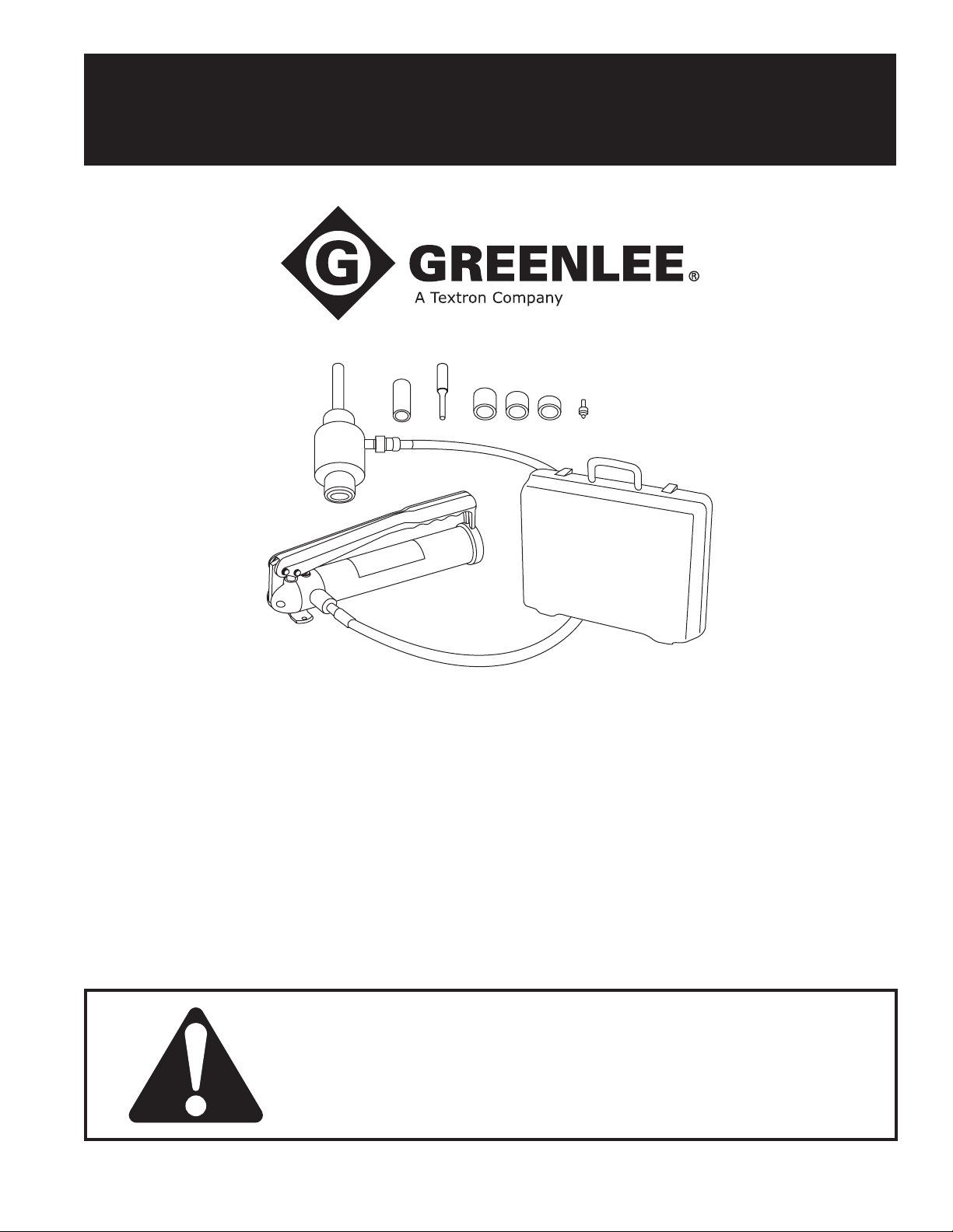
The Greenlee hydraulic punch driver sets combine
the 746 Hydraulic Ram with the 767 Hand Pump or
the 1725Foot Pump. These hydraulic driver sets
are intended to be used with either standard or
Slug-Buster® punches and dies to punch holes through
plastic, berglass, aluminum, and steel. Greenlee
Slug-Splitter® punches, dies, and draw studs are
capable of punching through all of these materials and
stainless steel.
Round punches are available for punching holes from
12.7 mm through 144 mm (1/2" through 5-5/8") in
diameter, including 1/2" through 5" conduit and pipe
sizes. Other shapes are available — square, special
square, rectangular, “D”, double “D”, electronic connector, oiltight with notches, and key.
The maximum thickness of material that the punch can
penetrate depends on the size and shape of the punch.
Refer to the instruction manual supplied with the punch
for individual punch capacities.
Safety
Safety is essential in the use and maintenance of
Greenlee tools and equipment. This instruction manual
and any markings on the tool provide information for
avoiding hazards and unsafe practices related to the
use of this tool. Observe all of the safety information
provided.
Purpose of this Manual
This manual is intended to familiarize all personnel with
the safe operation and maintenance procedures for the
following Greenlee hydraulic punch driver kits:
• 38456
• 38520
• 7306/7306SB
• 7310/7310SB
• 7506
• 7606SB
• 7610SB
• 7625/7625Pg/7625PgSB
• 7646/7646Pg/7646PgSB
Keep this manual available to all personnel.
All specications are nominal and may change as design
improvements occur. Greenlee Textron Inc. shall not be liable for
damages resulting from misapplication or misuse of its products.
Kwik-Stepper, Slug-Buster, and Slug-Splitter are registered
trademarks of GreenleeTextron Inc.
KEEP THIS MANUAL
Greenlee / A Textron Company 4455 Boeing Dr. • Rockford, IL 61109-2988 USA • 815-397-7070
Find Quality Products Online at: [email protected]
www.GlobalTestSupply.com
2
Page 3
IMPORTANT SAFETY INFORMATION
SAFETY
ALERT
SYMBOL
This symbol is used to call your attention to hazards
or unsafe practices which could result in an injury or
property damage. The signal word, dened below,
indicates the severity of the hazard. The message
after the signal word provides information for preventing or avoiding the hazard.
Immediate hazards which, if not avoided, WILL result
in severe injury or death.
Hazards which, if not avoided, COULD result in
severe injury or death.
Hazards or unsafe practices which, if not avoided,
MAY result in injury or property damage.
Read and understand all of the
instructions and safety information
in this manual before operating or
servicing this tool.
Failure to observe this warning could
result in severe injury or death.
Hydraulic Punch Driver
Electric shock hazard:
Do not use this tool near live circuits.
This includes, but is not limited to, the
following:
• near circuit breaker panels or fuse
boxes with energized circuits
• near junction boxes with energized
circuits
Failure to observe this warning could
result in severe injury or death.
Skin injection hazard:
• Hand-tighten all couplers completely before operating the pump.
Do not use tools to tighten the
couplers.
• Do not use hands to check for
leaks.
• Do not hold hose or couplers while
the hydraulic system is pressurized.
• Release the hydraulic pressure
before disconnecting the hoses or
couplers, and before servicing the
pump or accessory.
Oil under pressure easily punctures
skin causing serious injury, gangrene or death. If you are injured by
escaping oil, seek medical attention
immediately.
Wear eye protection when operating
or servicing this tool.
Failure to wear eye protection could
result in serious eye injury from ying
debris or hydraulic oil.
Greenlee / A Textron Company 4455 Boeing Dr. • Rockford, IL 61109-2988 USA • 815-397-7070
Find Quality Products Online at: [email protected]
www.GlobalTestSupply.com
3
Page 4
Hydraulic Punch Driver
IMPORTANT SAFETY INFORMATION
A component failure could throw
broken parts.
• Do not allow anyone to stand in
front of the punch or behind the
hydraulic ram.
• Close access doors or covers on
any equipment that is in line with
the punch or ram.
Failure to observe this warning could
result in severe injury or death.
Do not attempt to punch a hole
through two or more layers of material. This will bend or break the draw
stud, and could throw parts with great
force.
Failure to observe this warning could
result in severe injury or death.
Set up the tool properly. An improper setup could
cause a component to fail and strike nearby personnel with great force.
• Thread the punch completely onto the draw stud.
All of the punch threads must be engaged by the
draw stud threads. Incomplete assembly could
cause a component failure.
• Use only Greenlee punches, dies, and draw studs.
Other manufacturers’ components might not withstand the forces generated by this punch driver.
Failure to observe these warnings could result in
severe injury or death.
Replace worn, damaged or missing components
with Greenlee replacement parts. Worn or damaged
components can fail, resulting in injury or property
damage.
• Inspect the pump, hoses, couplers, and ttings for
wear or damage.
• Inspect all punch components (punch, die, draw
stud, etc.) for wear or damage.
Failure to observe these warnings could result in
severe injury or death.
Do not exceed the rated capacity of this tool.
Exceeding the rated capacity could cause a component failure, which could throw broken parts with
great force.
Failure to observe this warning could result in severe
injury or death.
The punch driver will fall free when the punch is
complete.
• Support the weight of the tool when punching.
• Do not allow anyone to stand beneath an overhead
punch.
Failure to observe this warning may result in injury or
property damage.
Use this tool for the manufacturer’s intended purpose
only. Any other use may result in injury or property
damage.
This punch system was designed for a maximum
operating pressure of 450 bar (6500 psi).
• Use this punch system with the Greenlee 767 Hand
Pump or 1725 Foot Pump only.
• Connect the pump to the ram with Greenlee hoses
and couplers only.
Use of any other hoses or couplers could result in
injury from a component failure.
Greenlee / A Textron Company 4455 Boeing Dr. • Rockford, IL 61109-2988 USA • 815-397-7070
Find Quality Products Online at: [email protected]
www.GlobalTestSupply.com
4
Page 5
Setup and Operation Instructions
Hydraulic Punch Driver
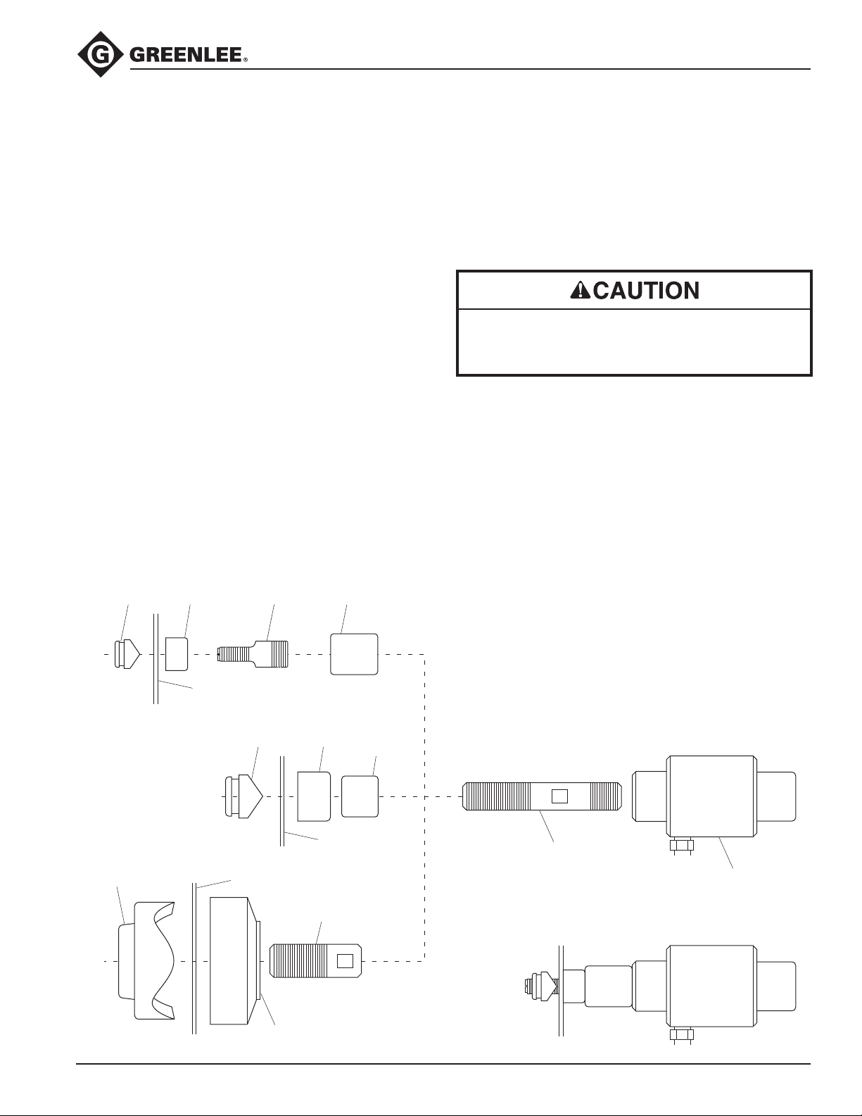
1. Remove the dust caps from the couplers; attach the
hose to the ram and to the pump. Thread the dust
caps together.
Note: Hand-tighten the couplers completely until all
threads are engaged. Do not use tools.
2. Select the punch, die, and draw stud that will make
the appropriate size hole.
3. Determine and mark the exact location for the hole.
Using a drill bit that is slightly larger than the draw
stud, drill a hole. This is the pilot hole.
4. Thread the 3/4" piston shaft (B) completely into the
ram (A). Refer to the illustration.
Note: For a punch and die with a 3/8" center hole,
thread the 3/8" adapter draw stud (F) into the end of
the piston shaft. For a punch and die with a 1-1/8"
center hole, thread the screw sleeve (E) onto the
piston shaft.
5. Install spacers as necessary. Refer to the illustrations on this page.
6. Slide the die over the draw stud with the open end
of the die facing away from the ram.
7. Insert the draw stud through the pilot hole.
3/8" Adapter
Punch
Die
Draw Stud
Spacer
8. Thread the punch onto the draw stud with the
cutting surfaces of the punch facing the material.
Tighten the punch by hand until the spacers, die,
material, and punch are snug.
Note: All of the punch threads must be engaged by
the draw stud threads. If any of the punch threads
are not engaged, dis-assemble the setup, remove
one of the spacers, and reassemble the setup.
Do not operate the pump after ram motion stops.
Continuing to operate the pump lever after the ram
stops will damage the ram.
Note: If the ram stops before the hole is complete,
stop pumping. Check that the setup is correct
and that you have not exceeded the tool’s capacity. Refer to the setup instructions. If necessary,
disassemble the setup and add a spacer.
9. Activate the pump. For specic instructions, refer to
the operating manual supplied with the pump.
Note: Support the weight of the ram when operating the pump. This will prevent the ram from falling
when the punch is complete.
10. Release the pressure at the pump.
Material
Punch Die Spacer
as needed
Material
Punch
Greenlee / A Textron Company 4455 Boeing Dr. • Rockford, IL 61109-2988 USA • 815-397-7070
Material
1-1/8" Sleeve
Die
5
3/4" Draw Stud
Ram
Completed Assembly
Find Quality Products Online at: [email protected]
www.GlobalTestSupply.com
Page 6
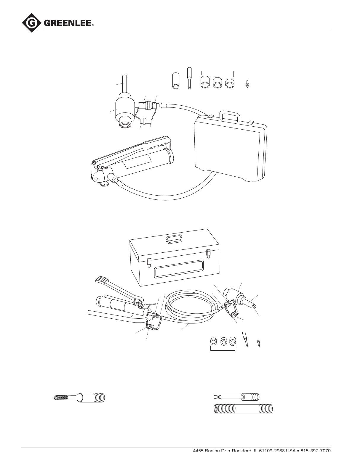
Illustration —Punch Driver
7646 Hydraulic Punch Driver with 767 Hand Pump
B
C
N
A
D
O
L
M
E F
Hydraulic Punch Driver
G
I K
HJ
R
7625 Hydraulic Punch Driver with 1725 Foot Pump
P
C
D
O
For punching mild steel, 3/8" drive:
S
C
N
Q
For punching stainless steel:
N
H I J
A
E
B
O
D
FGK
52042828
Greenlee / A Textron Company 4455 Boeing Dr. • Rockford, IL 61109-2988 USA • 815-397-7070
Find Quality Products Online at: [email protected]
www.GlobalTestSupply.com
50294512
50294520
(for use with Slug-Splitter punches and dies)
6
Page 7
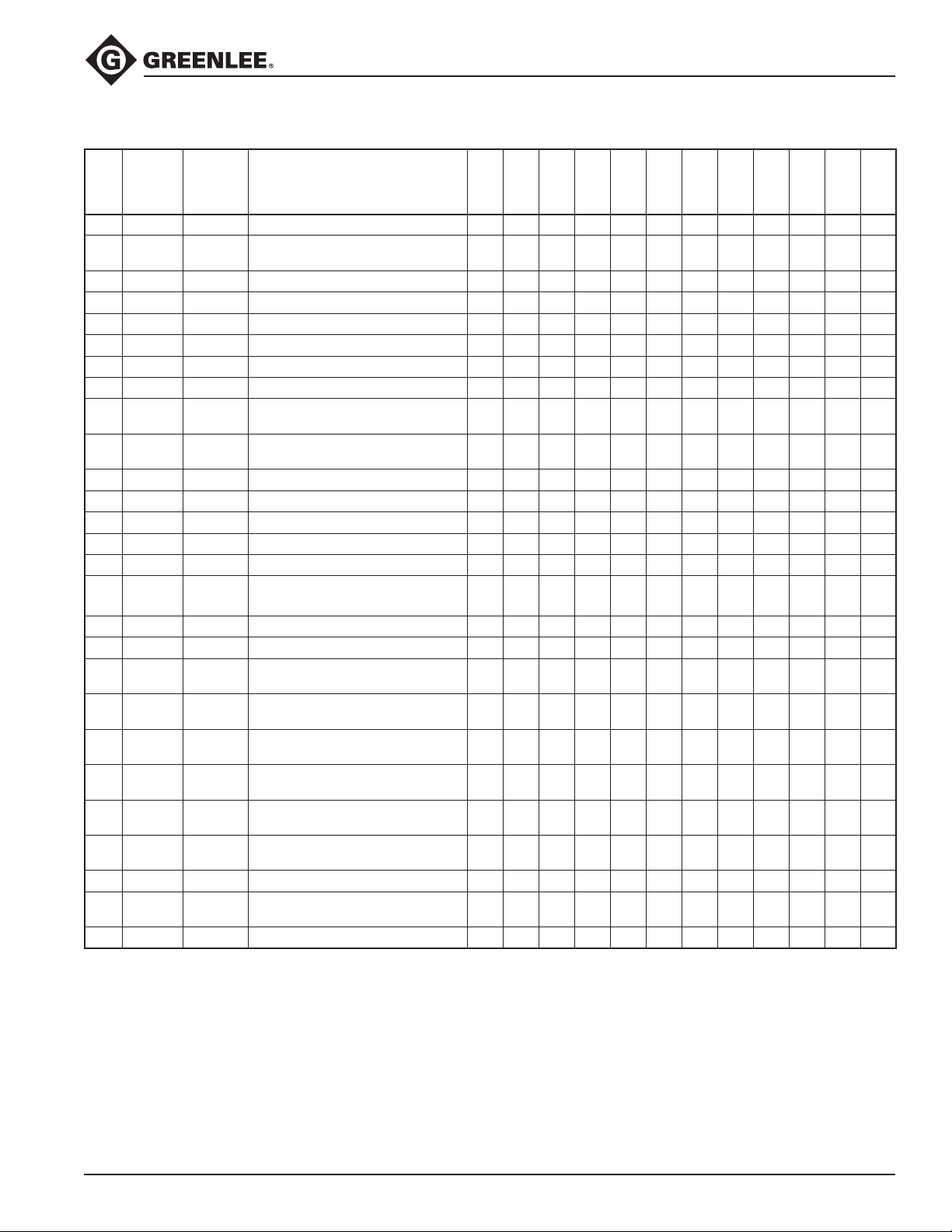
Parts List—Punch Driver
Hydraulic Punch Driver
Key Cat. No.
A 746 17091 Ram (includes keys B, C, D) 1 1 1 1 1 1 1 1 1 1
746SS 30387
29451 29451 7/16" Stainless Steel Draw Stud 1
29452 29452 3/4" Stainless Steel Draw Stud 1
B 2113B 10109 3/4" Piston Shaft 1 1 1 1 1 1 1 1 1 1
C 54167 54167 1/4" Coupler Unit 1 1 1 1 1 1 1 2 2 2 1
D 54168 54168 Dust Plug 1 1 1 1 1 1 1 2 2 2 1
E 1557AA 03170 Screw Sleeve 1 1 1 1 1 1 1 1 1 1
F 20963 20963
G 15908 15908
H 1924AA 03248 Short Spacer 1 1 1 1 1 1 1 1 1 1 1
I 1925AA 03249 Medium Spacer 1 1 1 1 1 1 1 1 1 1 1
J 1926AA 06904 Long Spacer 1 1 1 1 1 1 1 1 1 1 1
K 34410 34410 Kwik-Stepper
L 767 13284 Hydraulic Hand Pump 1 1 1 1 1 1 1 1
M 38316 38316
N 54169 54169 1/4" Coupler Unit 1 1 1 1 1 1 1 2 2 2 1
O 54170 54170 Dust Cap 1 1 1 1 1 1 1 2 2 2 1
06302 06302
P 1725 31353
Q 37729 37729
52515 52515
R 30206 30206
R 05387 05387
S 23955 23955 Metal Carrying Case 1 1 1
30236 30236
31068 31068 Metal Carrying Case 1
UPC No.
78-3310-
Description
Ram (includes keys C, D
and 29452)
3/8" Adapter Draw Stud
(3/4–16 x 3/8–24)
Spacer Group
(includes keys H, I, J)
®
Pilot Bit 1 1 1 1 1 1 1 1 1 1 1
1/4" x 3' High-Pressure Hose Unit
(includes keys N, O)
1/4" x 3' High-Pressure Hose
with Swivel (without couplers)
Hydraulic Foot Pump
(includes keys C, D)
1/4" x 10' High Pressure Hose Unit
(includes two each of keys N, O)
1/4" x 10' High Pressure Hose
Replacement (without couplers)
Plastic Carrying Case,
1/2"–2" Conduit
Plastic Carrying Case,
1/2"–4" Conduit
Plastic Carrying Case,
2-1/2"–4" Conduit
7646
1 1 1 1 1 1 1 1 1 1
1 1 1 1 1 1 1 1 1 1 1
1 1 1 1 1 1 1 1
1 1 1 1 1 1 1 1
1 1 1
7306SB
7306
38520
7310SB
1 1 1 1
7310
7625
38456
1 1 1
1 1 1
7606SB
7610SB
1
7304
7506
1
Greenlee / A Textron Company 4455 Boeing Dr. • Rockford, IL 61109-2988 USA • 815-397-7070
Find Quality Products Online at: [email protected]
www.GlobalTestSupply.com
7
Page 8
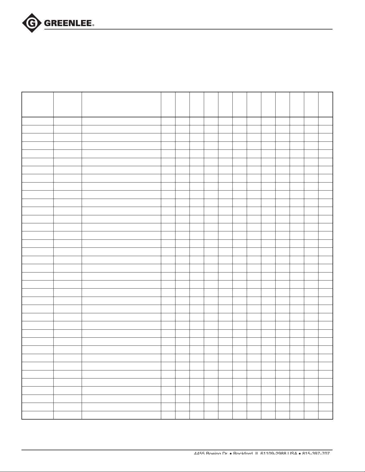
Hydraulic Punch Driver
Parts List—Punches
• Standard and Slug-Buster punches, dies, and draw studs listed in the following table
are capable of punching a maximum of 10 (0.1344", 3 mm) gauge mild steel.
• Slug-Splitter punches, dies, and draw studs listed in the following table
are capable of punching a maximum of 10 (0.1344", 3 mm) gauge stainless steel.
Cat. No.
721–1/2 31756 1/2" Slug-Buster Punch 1 1 1 1 1 1 1 1
14722 14722 1/2" Die 1 1 1 1 1 1 1 1
721–3/4 31757 3/4" Slug-Buster Punch 1 1 1 1 1
123AV 04008 3/4" Standard Punch 1 1 1
124AV 06972 3/4" Die 1 1 1 1 1 1 1 1
721–1 31758 1" Slug-Buster Punch 1 1 1 1 1
125AV 04010 1" Standard Punch 1 1 1
126AV 04011 1" Die 1 1 1 1 1 1 1 1
721–1-1/4 31759 1-1/4" Slug-Buster Punch 1 1 1 1 1
127AV 06974 1-1/4" Standard Punch 1 1 1
128AV 04013 1-1/4" Die 1 1 1 1 1 1 1 1
721–1-1/2 31760 1-1/2" Slug-Buster Punch 1 1 1 1 1
439AV 06978 1-1/2" Standard Punch 1 1 1
440AV 04061 1-1/2" Die 1 1 1 1 1 1 1 1
721–2 31761 2" Slug-Buster Punch 1 1 1 1 1
441AV 04062 2" Standard Punch 1 1 1
442AV 04063 2" Die 1 1 1 1 1 1 1 1
1429AV 04175 2-1/2" Punch 1 1 1 1 1 1
1430AV 04177 2-1/2" Die 1 1 1 1 1 1
1431AV 04180 3" Punch 1 1 1 1 1 1
1432AV 04183 3" Die 1 1 1 1 1 1
2982AV 04653 3-1/2" Punch 1 1 1 1
2981AV 04652 3-1/2" Die 1 1 1 1
2984AV 04655 4" Punch 1 1 1 1 1 1
2983AV 04654 4" Die 1 1 1 1 1 1
28154 28154 1/2" Slug-Splitter Punch 1
28155 28155 1/2" Slug-Splitter Die 1
28156 28156 3/4" Slug-Splitter Punch 1
28157 28157 3/4" Slug-Splitter Die 1
28158 28158 1" Slug-Splitter Punch 1
28159 28159 1" Slug-Splitter Die 1
28160 28160 1-1/4" Slug-Splitter Punch 1
28161 28161 1-1/4" Slug-Splitter Die 1
28162 28162 1-1/2" Slug-Splitter Punch 1
28163 28163 1-1/2" Slug-Splitter Die 1
28165 28165 2" Slug-Splitter Punch 1
28166 28166 2" Slug-Splitter Die 1
UPC No.
78-3310-
Description
7646
7306SB
7306
7310SB
38456
7310
38520
7625
7606SB
7610SB
7304
7506
Greenlee / A Textron Company 4455 Boeing Dr. • Rockford, IL 61109-2988 USA • 815-397-7070
Find Quality Products Online at: [email protected]
www.GlobalTestSupply.com
8
Page 9
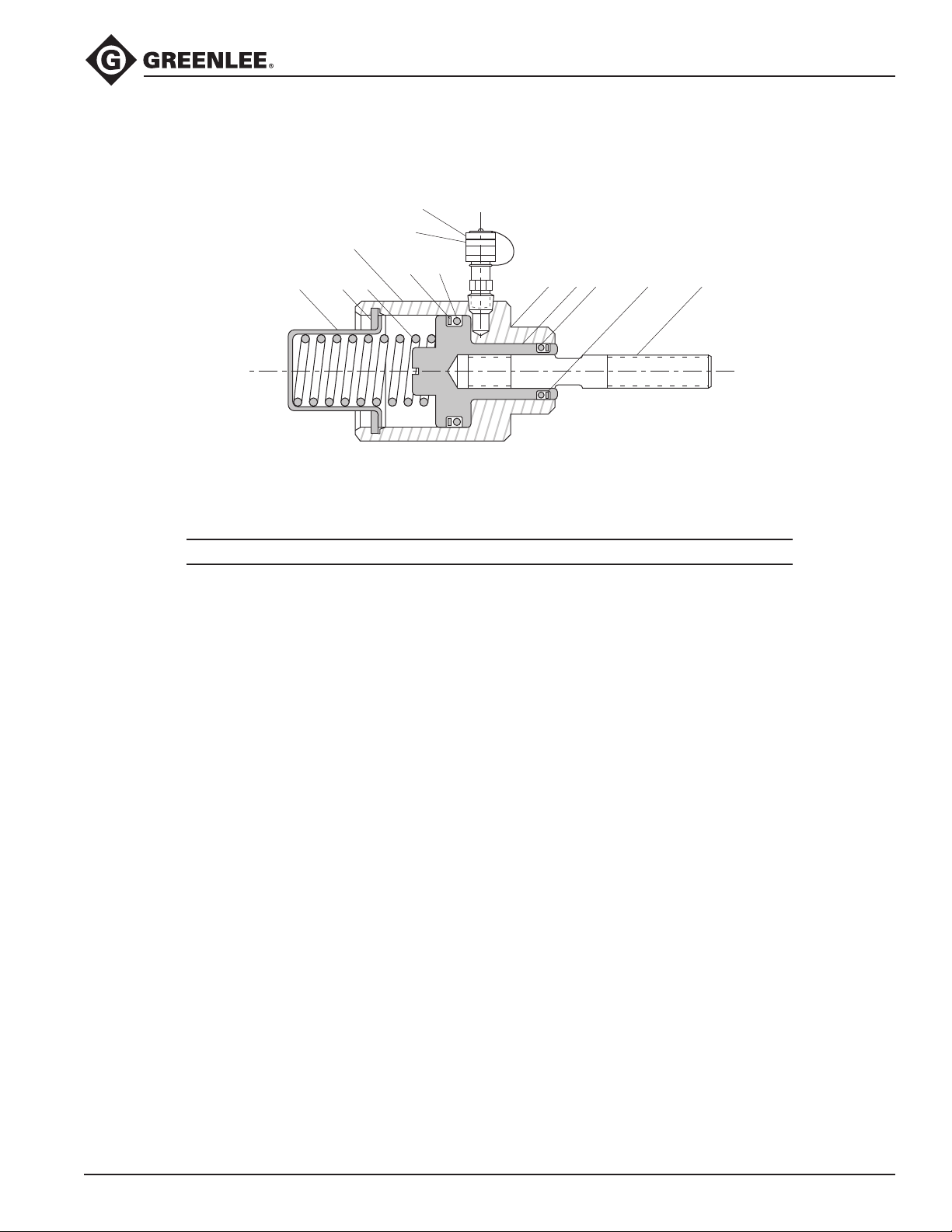
Illustration and Parts List—Ram
Hydraulic Punch Driver
Serial No.
Location
10
Key Part No. Description Qty
1* 52045040 Shaft (746 M-3) ......................................................................................... 1
50294520 Shaft (746 SS) ........................................................................................... 1
2** 50170937 Piston ........................................................................................................ 1
3 50170953 Cylinder ..................................................................................................... 1
4 50112511 Spring, Compression ................................................................................ 1
5 50112538 Retainer ..................................................................................................... 1
6 90541677 Coupler, 1/4" Quick Disconnect ................................................................ 1
7 90541685 Plug, Protective ......................................................................................... 1
8 90503384 O-ring, 7/8" x 1-1/8" x 1/8" ....................................................................... 1
9 90503899 O-ring, 2" x 2-3/8" x 3/16" ........................................................................ 1
10 90503902 Ring, Retainer ........................................................................................... 2
11 90508327 Ring, 2" x 2-3/8" x 3/16" Spiral Backup ................................................... 1
12 90513398 Ring, 7/8" x 1-1/8" x 1/8" Spiral Backup .................................................. 1
50145525 Packing Repair Kit (includes items 8, 9, 11, and 12) ................................ 1
50121219 Decal, Safety (not shown) ......................................................................... 1
6
9
11
45
3 2 8 12 1
7
* 52045041 Supplied with the 746 and used with standard punches
and Slug-Buster punches
** 50294520 Supplied with the 746 SS and used with Slug-Splitter
punches and dies
Greenlee / A Textron Company 4455 Boeing Dr. • Rockford, IL 61109-2988 USA • 815-397-7070
Find Quality Products Online at: [email protected]
www.GlobalTestSupply.com
9
Page 10

Maintenance
The pump and ram require little maintenance. Use the
tool with care to keep dirt and grit out of the hydraulic
system. All internal working parts are lubricated by the
hydraulic oil, so that no other lubrication is necessary.
Hydraulic Punch Driver
Find Quality Products Online at: [email protected]
www.GlobalTestSupply.com
 Loading...