

Page 1
INSTRUCTION MANUAL
763 & 764M4
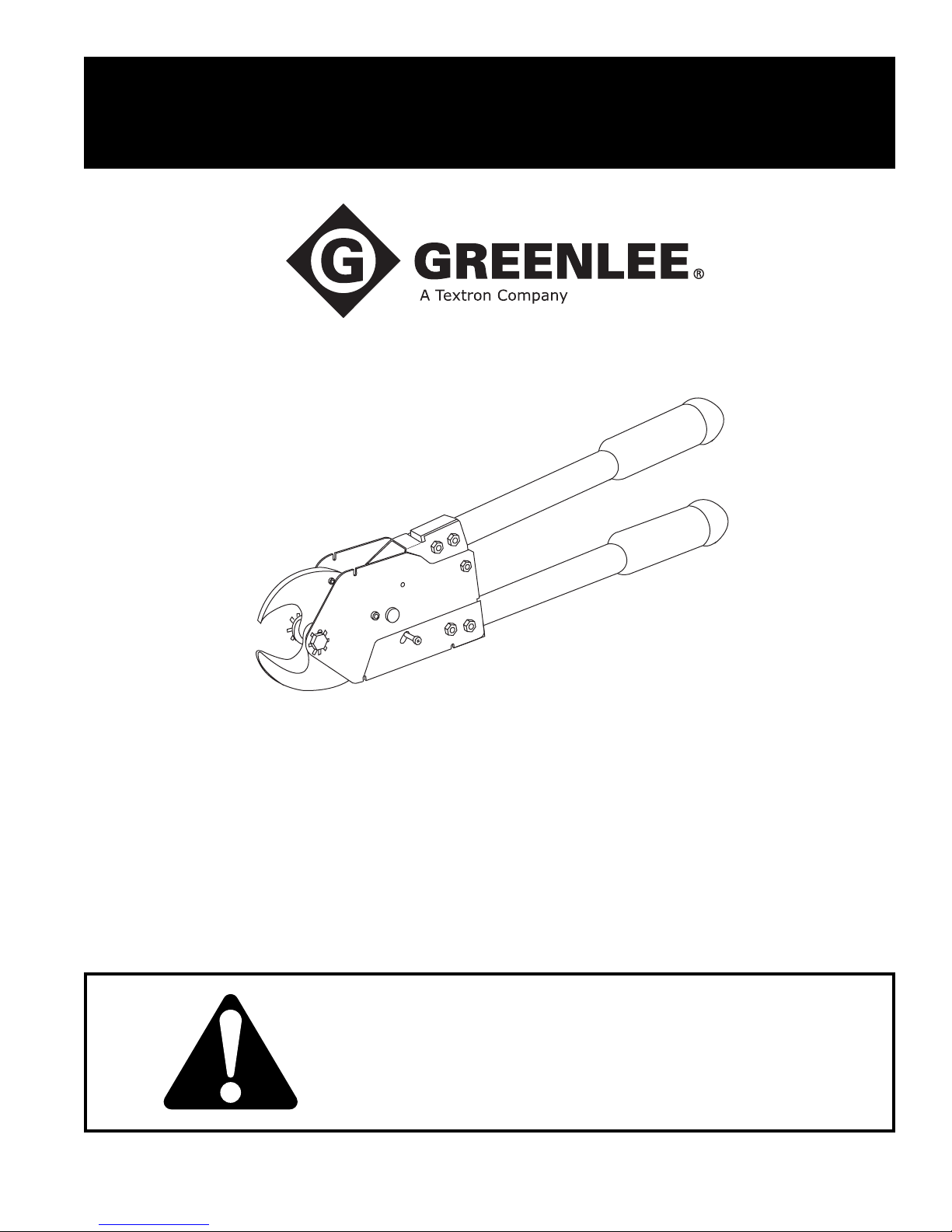
Ratchet Cable Cutters
99928752 © 2006 Greenlee Textron Inc. IM 1360 REV 2 5/06
Read and understand all of the instructions and
safety information in this manual before operating
or servicing this tool.
Page 2

763 and 764M4 Ratchet Cable Cutter
Table of Contents
Description ..................................................................... 2
Purpose of this Manual .................................................. 2
Important Safety Instructions ...................................... 3-4
Identification ...................................................................5
Specifications .................................................................5
Operation ....................................................................... 6
Maintenance
General ...................................................................... 7
Cleaning the cutter.....................................................7
Lubricating the cutter ................................................. 7
Disassembly .............................................................. 8
Assembly .............................................................. 9-11
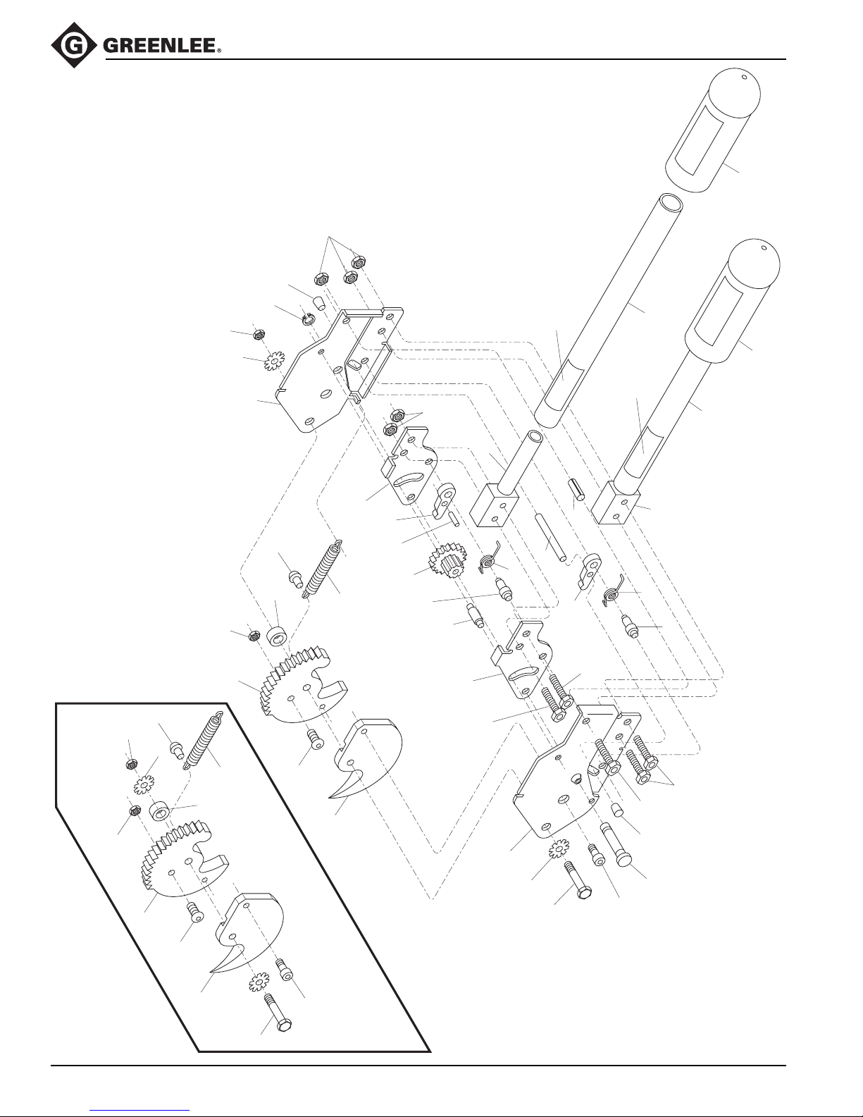
Exploded View ............................................................. 12
Parts List ...................................................................... 13
Description
Safety
Safety is essential in the use and maintenance of
Greenlee tools and equipment. This instruction manual
and any markings on the tool provide information for
avoiding hazards and unsafe practices related to the
use of this tool. Observe all of the safety information
provided.
Purpose
This instruction manual is intended to familiarize personnel with the safe operation and maintenance procedures
for the following Greenlee 763 and 764M4 Cable Cutter.
Keep this manual available to all personnel.
Replacement manuals are available upon request
at no charge.
Greenlee 763 and 764M4 Ratchet Cable Cutters are
non-insulated cutting tools intended for use on copper
and standard aluminum electrical cable. The 763 will
accommodate up to 500 MCM copper or 795 MCM
aluminum cable. The 764M4 will cut up to 750 MCM
copper or 795 MCM aluminum cable.
Both cable cutters ratchet and are equipped with fiberglass handles and rubber grips to limit operator fatigue.
They are not intended for use on ACSR (aluminum
cable, steel-reinforced) cable.
All specifications are nominal and may change as design improvements occur. Greenlee Textron Inc. shall not be liable for damages
resulting from misapplication or misuse of its products.
Loctite is a registered trademark of Loctite Corporation.
416 Super Bonder is a registered trademark of Loctite Corporation.
Molykote is a registered trademark of Dow Corning Corporation.
Greenlee / A Textron Company 2 4455 Boeing Dr. • Rockford, IL 61109-2988 USA • 815-397-7070
KEEP THIS MANUAL
Page 3
IMPORTANT SAFETY INFORMATION
SAFETY
ALERT
SYMBOL
This symbol is used to call your attention to hazards
or unsafe practices which could result in an injury
or property damage. The signal word, defined below,
indicates the severity of the hazard. The message
after the signal word provides information for preventing or avoiding the hazard.
Immediate hazards which, if not avoided, WILL result
in severe injury or death.
763 and 764M4 Ratchet Cable Cutter
Read and understand all of the
instructions and safety information
in this manual before operating or
servicing this tool.
Failure to observe this warning could
result in severe injury or death.
Hazards which, if not avoided, COULD result in
severe injury or death.
Hazards or unsafe practices which, if not avoided,
MAY result in injury or property damage.
Greenlee / A Textron Company 3 4455 Boeing Dr. • Rockford, IL 61109-2988 USA • 815-397-7070
Page 4
763 and 764M4 Ratchet Cable Cutter
IMPORTANT SAFETY INFORMATION
Electric shock hazard:
This is not an insulated tool.
Contact with live circuits could result
in severe injury or death.
Keep hands away from closing
blades.
Pinch points:
Keep hands away from moving
parts.
Wear eye protection when using this
tool. Failure to wear eye protection
could result in serious eye injury
from flying debris.
• This tool is intended for two-handed operation.
Maintain a firm grip on both handles during
operation.
• Do not cut ACSR or steel.
• Do not exceed the rated capacity of this tool.
• Inspect before use. Replace any worn or damaged
parts.
• Do not perform any service or maintenance other
than as described in this manual.
Failure to observe these precautions may result in
injury or property damage.
Greenlee / A Textron Company 4 4455 Boeing Dr. • Rockford, IL 61109-2988 USA • 815-397-7070
Page 5
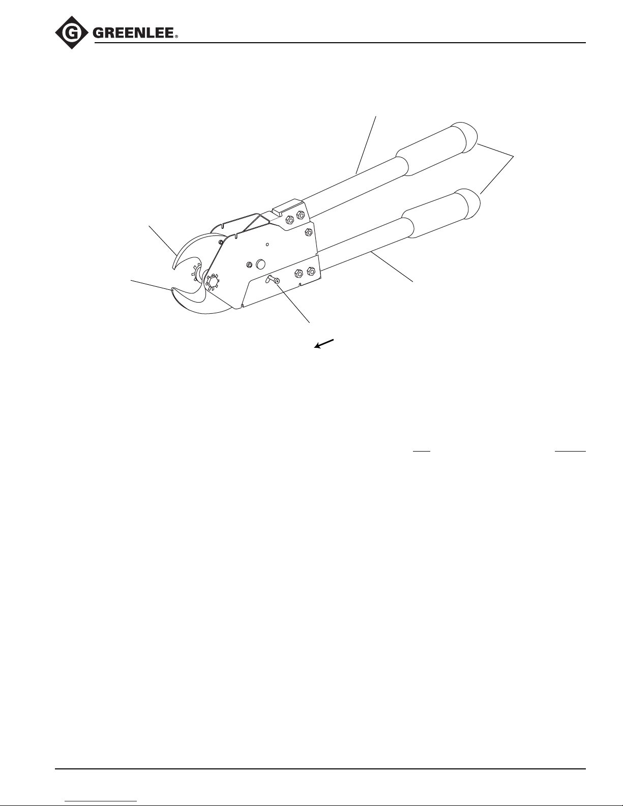
Identification
Movable
Stationary
Jaw
Jaw
763 and 764M4 Ratchet Cable Cutter
Movable
handle
Grips
Stationary
Release
knob
handle
Release
Specifications
763 764M4
Mass/Weight ...................................................................................2.15 kg (4.75 lb) ............................ 2.4 kg (5.25 lb)
Length ............................................................................................ 349 mm (13.75") ........................ 486 mm (19.125")
Width
at blades .............................................................................. 102 mm (4.03") ............................ 102 mm (4.03")
at handles ............................................................................ 132 mm (5.19") ................................. 152 mm (6")
Thickness ........................................................................................... 63.5 mm (2.5") ............................. 63.5 mm (2.5")
Jaw opening (minimum).................................................................... 30 mm (1.188") ............................ 30 mm (1.188")
Handle force at Maximum Copper Capacity......................................... 334 N (75 lb) ................................ 267 N (60 lb)
Maximum Rated Capacity
Copper (600-Volt Building Wire) .............................................. 240 mm2 (500 Kcmil) ................... 400 mm2 (750 Kcmil)
Aluminum (600-Volt Building Wire).......................................... 400 mm2 (795 Kcmil) ................... 400 mm2 (795 Kcmil)
Communications Cable.............................................................30 mm (1.188") O.D. .................... 30 mm (1.188") O.D.
Frequent Use
Copper (600-Volt Building Wire) ............................................... 170 mm2 (350 MCM) .................... 240 mm2 (500 MCM)
Aluminum (600-Volt Building Wire)...........................................240 mm2 (500 MCM) .................... 400 mm2 (750 MCM)
Greenlee / A Textron Company 5 4455 Boeing Dr. • Rockford, IL 61109-2988 USA • 815-397-7070
Page 6
Operation
Electric shock hazard:
This is not an insulated tool.
Contact with live circuits could result
in severe injury or death.
Wear eye protection when using this
tool. Failure to wear eye protection
could result in serious eye injury
from flying debris.
763 and 764M4 Ratchet Cable Cutter
1. Place the cable to be cut between the jaws.
2. Press the handles together until the ratchet clicks
once.
3. Open the handles until the ratchet clicks again.
4. Repeat steps 2 and 3 until cable is completely cut.
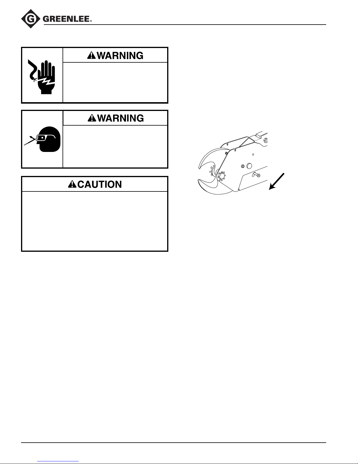
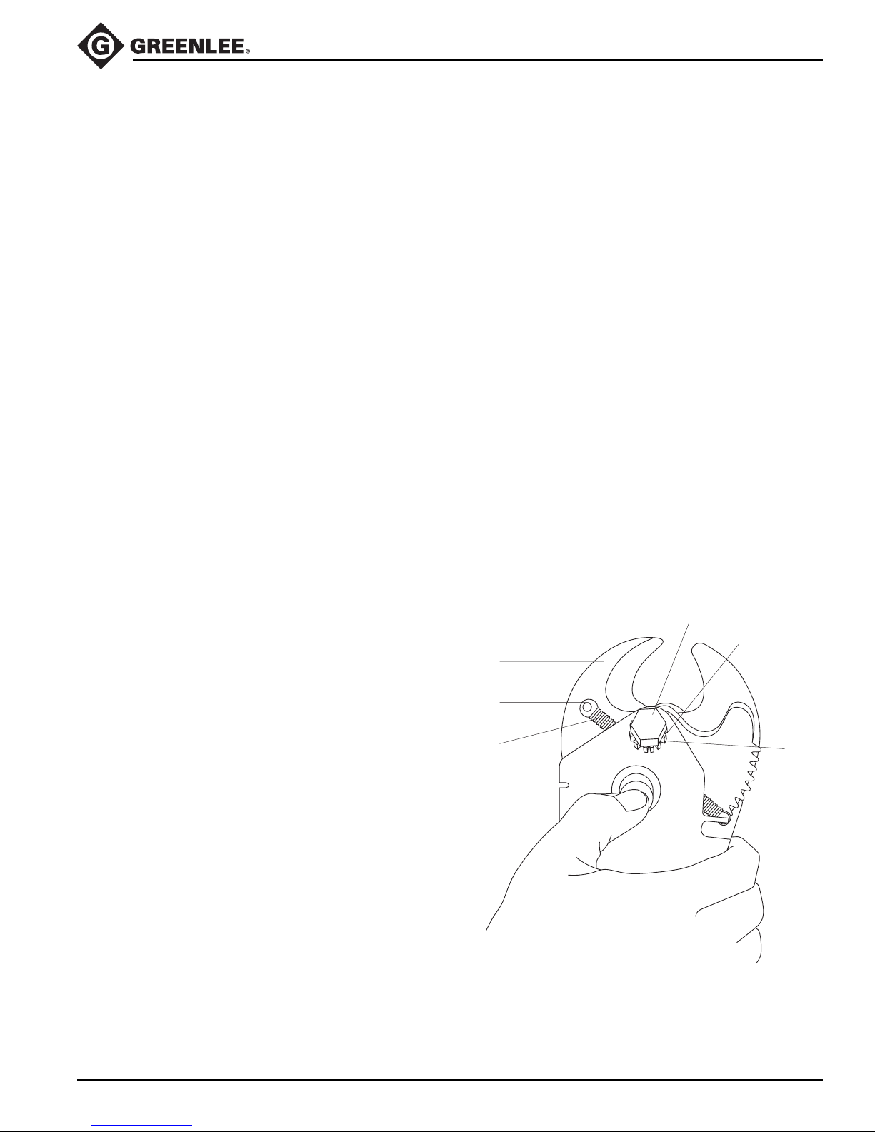
5. To open the blades, lift the movable handle until it
stops. Press the release knob outward as shown.
Release
• This tool is intended for two-handed operation.
Maintain a firm grip on both handles when using
this tool.
• Inspect before use. Replace any worn or damaged
parts.
Failure to observe these precautions may result in
injury or property damage.
Greenlee / A Textron Company 6 4455 Boeing Dr. • Rockford, IL 61109-2988 USA • 815-397-7070
Page 7
Maintenance
763 and 764M4 Ratchet Cable Cutter
General
Maintain the tool with care. Keep the blades sharp
and the tool clean for better and safer performance.
Follow instructions for lubricating the cutter; lubrication
prolongs the tool life and enables the tool to cut with less
force. Keep grips dry, clean and free from oil
and grease.
Cleaning the cutter
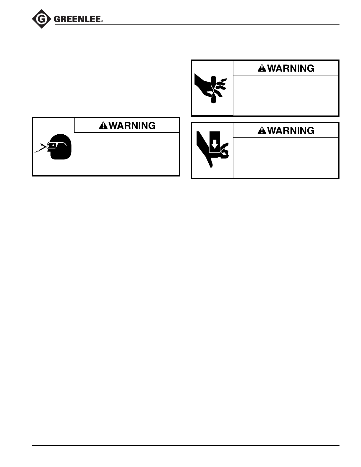
Wear eye protection when using this
tool. Failure to wear eye protection
could result in serious eye injury
from flying debris.
Blow dirt and/or cable particles out of the drive
mechanism with compressed air.
Lubricating the cutter
Keep hands away from closing
blades.
Pinch points:
Keep hands away from moving
parts.
Close jaws and place 3-in-1 oil or equivalent on the
blades. Oil the jaw bolt (25), spacer (4), and jaw areas
around them. Also oil the master gear (16) and pawls (15)
at their respective shafts (19) and contact surfaces. Oil
the inside of the housing plates (13, 23) where contacted
by the lever handle plates (14, 22). Open and close the
cutter to spread the oil.
Disassemble, clean, and lubricate the tool if it does not
operate smoothly.
Greenlee / A Textron Company 7 4455 Boeing Dr. • Rockford, IL 61109-2988 USA • 815-397-7070
Page 8

Maintenance (cont’d)
763 and 764M4 Ratchet Cable Cutter
Disassembly
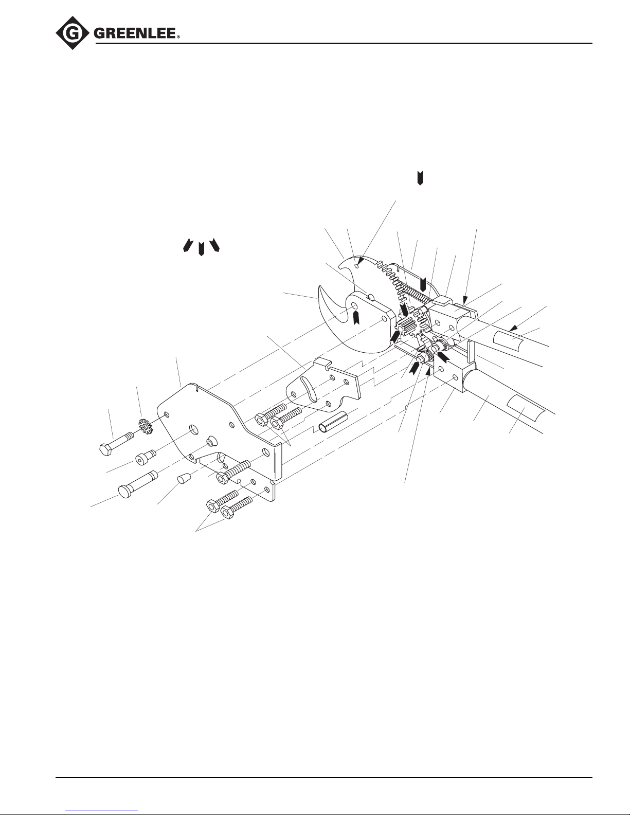
This tool consists of three basic operating mechanisms
(see Figure 1).
1. Cutter jaw mechanism: stationary jaw (1), movable
jaw (3), jaw bolt (25), jaw spacer (4), return spring (5),
and related hardware.
2. Jaw drive mechanism: master drive gear (16),
master gear shaft (26), drive pawl (15), pawl spring
(12), pawl shaft (19), top and bottom handle plates
(14, 22) and operating lever.
3. Jaw holding mechanism: holding pawl (15), pawl
spring (17), pawl shaft (19) and pawl release pin
(27).
Both the jaw mechanism and drive mechanism can
be removed and serviced without disassembly of the
housing.
1. Remove cap screw (21). Release tension on extension spring (5) by opening the operating lever and
rotating release pin (27) outward.
2. Remove nut (6).
3. Remove bolt (25) and spacer (4).
4. Disconnect spring (5) from housing (13).
5. Remove retaining ring (9) from gear shaft (26).
Also remove two screws (8) from stop pin (20).
6. Remove shaft (26) and gear (16).
7. Remove the operating lever assembly.
8. Remove rubber bumpers (10) from release pin (27).
9. Remove two housing screws (11). Lift housing from
tool.
10. Remove two screws (11) to disassemble operating
lever assembly and remove pawl (15), pawl spring
(12) and pawl shaft (19).
Greenlee / A Textron Company 8 4455 Boeing Dr. • Rockford, IL 61109-2988 USA • 815-397-7070
Page 9
Maintenance (cont’d)
Assembly
LUBRICATION
POINTS -
USE MOLYKOTE
®
22
1
763 and 764M4 Ratchet Cable Cutter
Figure 1
SPRING
ANCHOR PIN
JAW DRIVE
MECHANISM
20
14
28
19
12
OPERATING
LEVER
31
2,8
5,7
3
16
13
9,26
6,25
21
21
10
23
11*
11
JAW HOLDING
MECHANISM
*Note: Tighten to 19.2 - 21.4 Nm
(170-190 in-lb)
15
13
27
28
29
30
Greenlee / A Textron Company 9 4455 Boeing Dr. • Rockford, IL 61109-2988 USA • 815-397-7070
Page 10
Maintenance (cont’d)
Assembly (cont’d)
Note: Use Loctite® 262 Threadlocker on all screws
and tighten all 5/16" diameter screws to 190/170 in-lb.
Use Loctite 416 Super Bonder
release pin bumpers (10). Lubricate moving parts with
Molykote
1.
®
grease (see Figure 1).
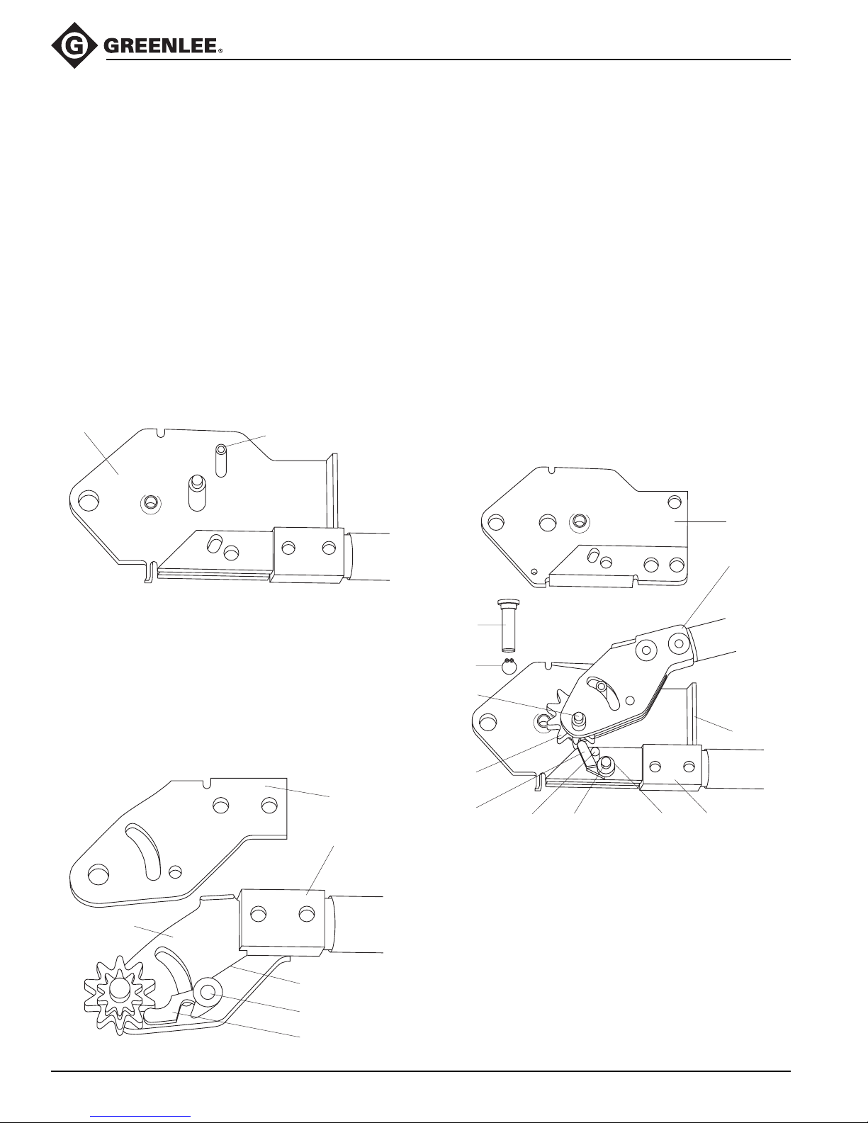
Assemble handle assembly (39) to bottom of housing
plate (13) using two screws (11).
2. Install stop pin (20). Place a spare 3/8" x 1.500"
screw through the master gear hole in bottom
housing plate (13) and place assembly on bench
with screws up (see Figure 2).
®
Figure 2
(cyanoacrylate) to attach
763 and 764M4 Ratchet Cable Cutter
4. Insert master gear (16) between top and bottom
handle plates against drive pawl (15) and assemble
over spare screw in bottom housing plate (see
Figure 4).
5. Place holding pawl (15) with release pin (27) and
spring (17) over hole in bottom housing plate and
insert lubricated pawl shaft (19). The pawl will
engage the master gear. The long leg of the spring
goes against the handle adapter (28) where it
touches the bottom housing plate and the short leg
goes under the pawl (see Figure 4).
6. Thread housing cover (35) between handle plates
above the master gear—between spring (17) and
handle adapter (28) (see Figure 4).
13
20
3. Lubricate pawl shaft (19) and assemble pawl shaft,
pawl (15) with pin (33) projecting from pawl surface,
spring (12), bottom handle plate (14) and top handle
plate (22) to handle assembly using two screws (11).
The long leg of the spring goes against the bottom
handle adapter (28) and the short leg goes under the
pawl (see Figure 3).
Figure 3
22
28
Figure 4
23
28
26
9
26
13
16
15
27 19 17 28
14
Greenlee / A Textron Company 10 4455 Boeing Dr. • Rockford, IL 61109-2988 USA • 815-397-7070
12
19
15
Page 11
Maintenance (cont’d)
Assembly (cont’d)
7. Place top housing plate (23) over tool assembly,
using spare 3/8" screw and release pin (27) for
alignment. Assemble nuts (18) loosely to hold
housing in place.
8. Lubricate gear shaft (26) and assemble in place of
3/8" spare screw.
9. Assemble retaining ring (9) to gear shaft (26).
10. Assemble bumpers (10) to pin (27).
763 and 764M4 Ratchet Cable Cutter
Note: To replace jaws, see steps 11-18; also see
Figure 5 and exploded view. To replace entire cutter head
(38), skip steps 11, 12, and 15.
11.
Assemble spring (5) to movable jaw (3) using stud (7).
12. Assemble screw (2) and nut (8) into movable jaw (3).
13. Reconnect spring (5) to housing (13).
14. Assemble fixed jaw (1), movable jaw (3) and spacer
(4) into housing assembly using lubricated bolt (25),
nut (6) and two nut retainers (24).
15. Assemble jaw anchor screw (21).
16. Tighten nut (6) to a maximum jaw clearance of
.2 mm (0.007"). To achieve .2 mm (0.007") clearance,
tighten nut (6) snugly so that jaws are against each
other. Then back off nut to the first open slot aligned
with the drive pin hole. There should be not more
than .2 mm (0.007") gap between blades. Operate
the cutter to ensure that the jaws move freely.
17. Bend tab (5) on nut retainer (24) to secure nut (6).
18. Apply adhesive Loctite 416 Super Bonder sparingly
to assemble two bumpers (10) (see Figure 1).
Figure 5
25
24
3
7
5
6
Greenlee / A Textron Company 11 4455 Boeing Dr. • Rockford, IL 61109-2988 USA • 815-397-7070
Page 12
Illustration
763 and 764M4 Ratchet Cable Cutter
32
18
10
9
6
31
29
6
Key 38
Cutterhead
8
24
13
14
7
4
8
3
7
24
5
4
2
5
1
18
28
15
33
16
19
20
22
12
11
23
35
27
15
11
30
29
28
17
19
11
34
10
32
3
2
1
25
Greenlee / A Textron Company 12 4455 Boeing Dr. • Rockford, IL 61109-2988 USA • 815-397-7070
24
25
21
26
21
Page 13

763 and 764M4 Ratchet Cable Cutter
Parts List
763 764 M4
Key Part No. Part No. Description Qty
1 50386255 50386255 Jaw, stationary cutter.........................................................................1
2 90505794 90505794 Screw, 1/4–20 x .500" socket head ................................................... 1
3 50384759 50384759 Jaw, movable cutter...........................................................................1
4 50355325 50355325 Spacer, 0.380" x .750" x .376"...........................................................1
5 90539850 90539850 Spring, extension 0.202" x .300" x 2.75" ...........................................1
6 90541197 90541197 Nut, hex, 3/8–24 ................................................................................1
7 90535995 90535995 Stud, 0.161" x .500" ........................................................................... 1
8 90541200 90541200 Nut, 1/4–20 lock.................................................................................1
9 90504534 90504534 Ring, retaining, Truarc® #5100-37 .....................................................1
10 90539427 90539427 Bumper, 0.187" x .375" x .500" rubber .............................................. 2
11* 90552652 90552652 Screw, cap, 5/16–24 x 1.25"..............................................................4
12 50381407 50381407 Spring, torsion ................................................................................... 1
13 50055690 50055690 Plate, housing bottom........................................................................1
14 50355260 50355260 Plate, bottom handle..........................................................................1
15 50356488 50356488 Pawl ...................................................................................................2
16 50356461 50356461 Gear, master 12T .............................................................................. 1
17 50356216 50356216 Spring, torsion, 0.380" x .450" x .140"...............................................1
18* F009550 F009550 Nut, 5/16–24 lock...............................................................................5
19 50355384 50355384 Shaft, pawl 0.312" x 1.00" .................................................................2
20 50384783 50384783 Pin, stop ............................................................................................. 1
21 90539877 90539877 Screw, cap, 5/16–18 x .312" socket head .........................................1
22 50355252 50355252 Plate, top handle................................................................................1
23 50399110 50055674 Plate, housing top .............................................................................. 1
24 50384813 50384813 Retainer, nut ......................................................................................2
25 90542690 90542690 Bolt, blade, 3/8–24 x 1.75" ................................................................1
26 50055402 50055402 Shaft, master gear .............................................................................1
27 90539419 90539419 Pin, roll, 0.187" x 2.00" ......................................................................1
28* 50384937 50384937 Adapter, handle .................................................................................2
29* 50055550 50355406 Handle ...............................................................................................2
30* 50034669 50034669 Decal, warning...................................................................................1
31* 50351907 50351907 Decal, small Greenlee safety ............................................................1
32* 50223003 50223003 Grip, rubber, 0.995" x 1.50" x 5.09"...................................................2
33 90540077 90540077 Pin, roll, 0.187" x .375" ......................................................................1
34 90505247 90505247 Screw, cap, 5/16–18 x 1.500"............................................................1
35 50057219 50057219 Spacer ............................................................................................... 1
Repair Parts List
Key Part No. Description Qty
38 50360370 Cutter head
* 50358855 Handle assembly - one handle and hardware for 764M4
* 50059521 Handle assembly - one handle and hardware for 763
Greenlee / A Textron Company 13 4455 Boeing Dr. • Rockford, IL 61109-2988 USA • 815-397-7070
(includes keys 1–8, 21, 24, 25, 33) ............................................... 1
(includes keys 11, 18, 28-32) ........................................................ 1
(includes keys 11, 18, 28-32) ........................................................ 1
Page 14

USA 800-435-0786 Fax: 800-451-2632
815-397-7070 Fax: 815-397-1865
Canada 800-435-0786 Fax: 800-524-2853
International +1-815-397-7070 Fax: +1-815-397-9247
4455 Boeing Drive • Rockford, IL 61109-2988 • USA • 815-397-7070
An ISO 9001 Company
www.greenlee.com
•
Greenlee Textron Inc. is a subsidiary of Textron Inc.
Printed in USA
 Loading...