

Page 1
INSTRUCTION MANUAL
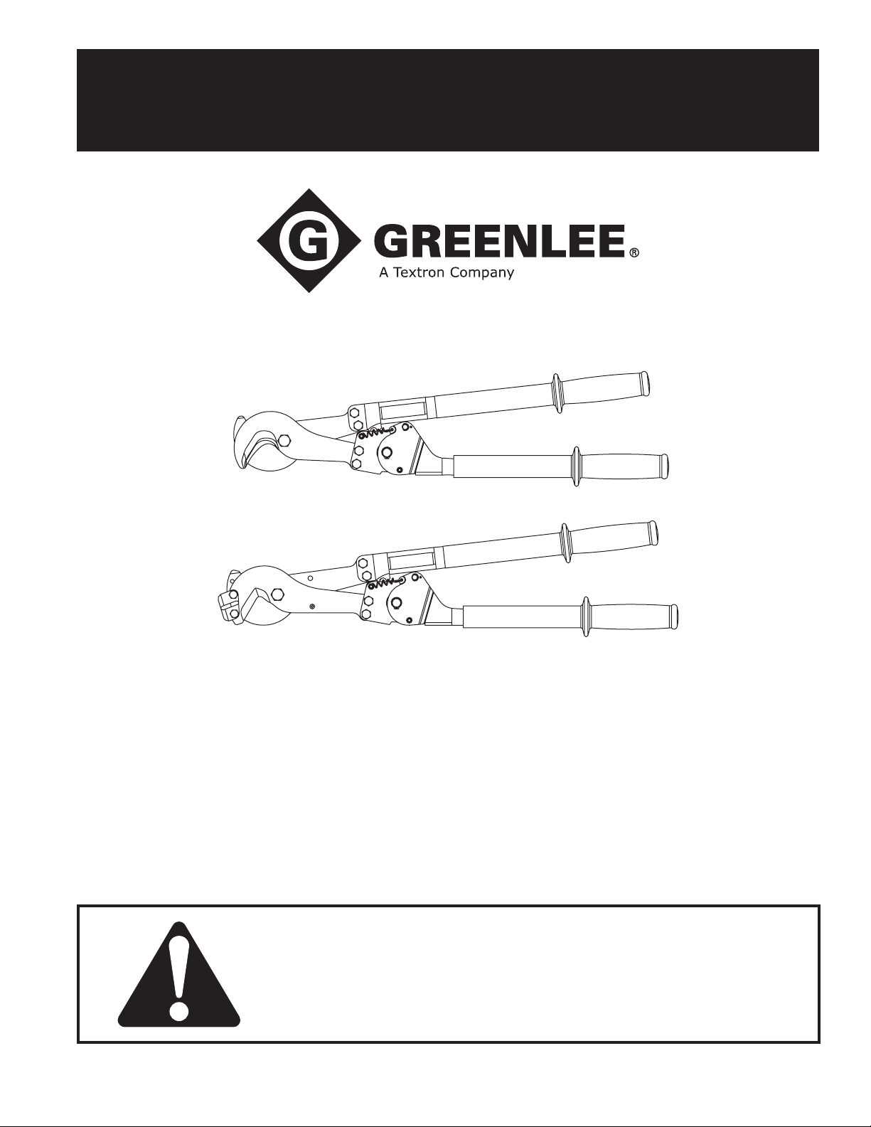
756 and 757
Ratchet Cable Cutters
Read and understand all of the instructions and
safety information in this manual before operating
or servicing this tool.
Register this product at www.greenlee.com
99990016 © 2012 Greenlee Textron Inc. IM 1032 REV 20 1/12
Page 2

756 and 757 Ratchet Cable Cutters
Table of Contents
Description .................................................................... 2
Safety ............................................................................ 2
Purpose of this Manual ................................................. 2
Important Safety Instructions ........................................ 3
Specications ................................................................ 4
Operation ....................................................................... 4
Maintenance ............................................................... 5-7
Illustration ...................................................................... 8
Parts List
756 ........................................................................ 9-10
757 ...................................................................... 11-12
Description
The Greenlee 756 and 757 Ratchet Cable Cutters are
non-insulated tools.
• The 756 is intended to cut copper and aluminum
cable up to 1500 kcmil.
• The 757 is intended to cut ACSR up to 954 kcmil and
1/2" soft steel rod.
Safety
Safety is essential in the use and maintenance of
Greenlee tools and equipment. This instruction manual
and any markings on the tool provide information for
avoiding hazards and unsafe practices related to the
use
of this tool. Observe all of the safety information
provided.
Purpose of this Manual
This instruction manual is intended to familiarize personnel with the safe operation and maintenance procedures
for the Greenlee 756 and 757 Ratchet Cable Cutters.
Keep this manual available to all personnel.
Replacement manuals are available upon request
at no charge at www.greenlee.com.
All specications are nominal and may change as design
improvements occur. Greenlee Textron Inc. shall not be liable for
damages resulting from misapplication or misuse of its products.
KEEP THIS MANUAL
Greenlee / A Textron Company 4455 Boeing Dr. • Rockford, IL 61109-2988 USA • 815-397-7070
2
Page 3
IMPORTANT SAFETY INFORMATION
SAFETY
ALERT
SYMBOL
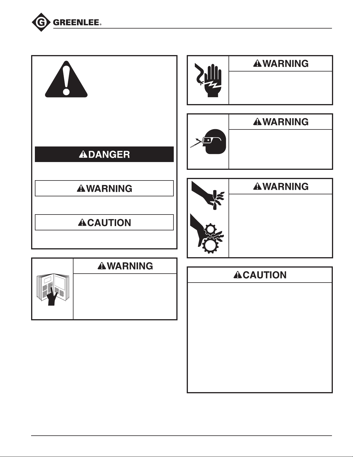
This symbol is used to call your attention to hazards
or unsafe practices which could result in an injury or
property damage. The signal word, dened below,
indicates the severity of the hazard. The message
after the signal word provides information for preventing or avoiding the hazard.
Immediate hazards which, if not avoided, WILL result
in severe injury or death.
756 and 757 Ratchet Cable Cutters
Electric shock hazard:
This is not an insulated tool. Contact
with live circuits could result in
severe injury or death.
Wear eye protection when using or
servicing this tool.
Failure to wear eye protection could
result in serious eye injury from
ying debris.
Hazards which, if not avoided, COULD result in
severe injury or death.
Hazards or unsafe practices which, if not avoided,
MAY result in injury or property damage.
Read and understand all of the
instructions and safety information
in this manual before operating or
servicing this tool.
Failure to observe this warning
could result in severe injury or death.
Keep hands away from the blades
• This tool is intended for two-handed operation.
Maintain a rm grip on both handles when using
this tool. Using this tool in any other manner can
result in injury or property damage.
• Inspect before use. Replace any worn or damaged
parts. A damaged or improperly assembled tool
can break and strike nearby personnel.
• Do not perform any service or maintenance other
than as described in this manual. Injury or damage
to the tool may result.
• Do not exceed the rated cutting capacity of this
tool. The tool may break and cause injury or
property damage.
Failure to observe these precautions may result in
injury or property damage.
and sprocket.
The spring-loaded mechanism could
close unexpectedly, resulting in
personal injury. Disengage the
spring before servicing this tool.
Greenlee / A Textron Company 4455 Boeing Dr. • Rockford, IL 61109-2988 USA • 815-397-7070
3
Page 4
Specifications
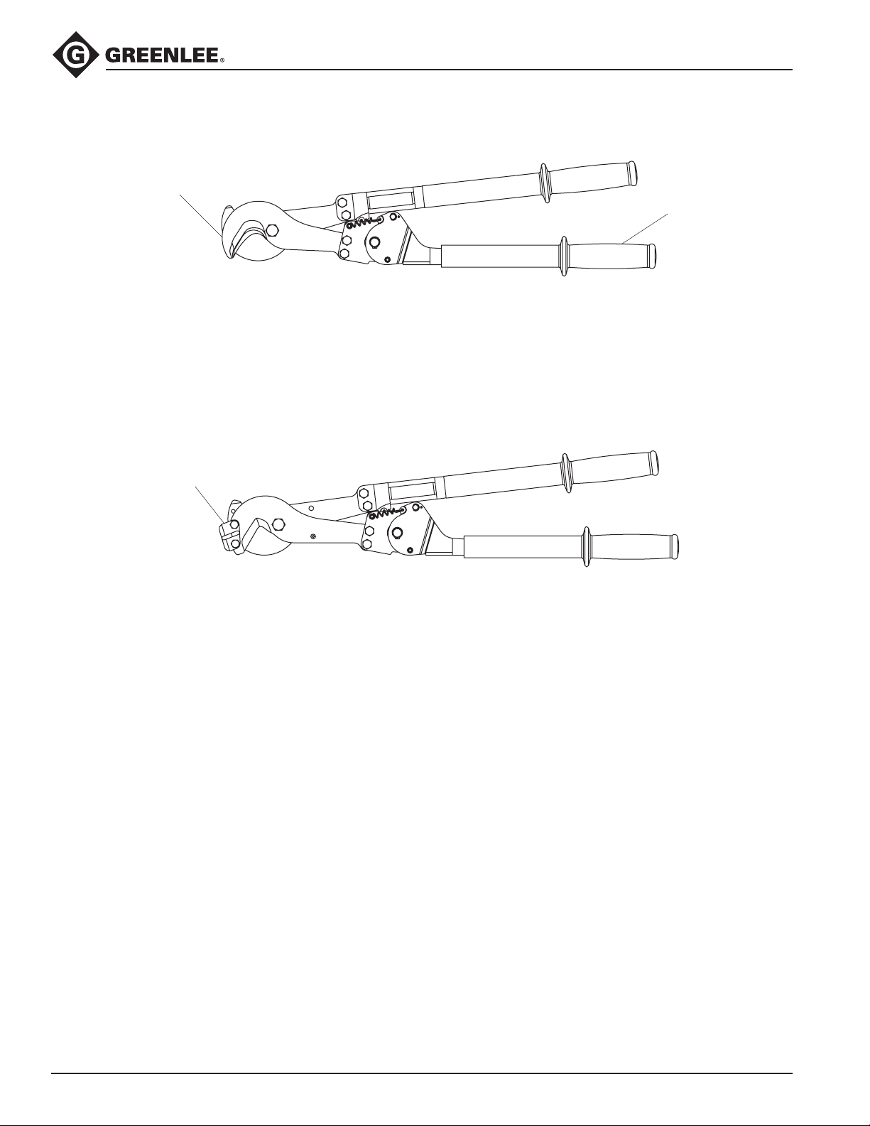
756 Ratchet Cable Cutter
Cutterhead
Weight ........................................................................................................4.5 kg (10 lb)
Length.................................................................................................. 69.85 cm (27.5")
Jaw Opening .............................................................................................. 5.08 cm (2")
Maximum Capacity....................................... 1500 kcmil (630 mm2) Copper/Aluminum
757 Ratchet Cable Cutter
756 and 757 Ratchet Cable Cutters
Grip
Keeper Unit
Weight .....................................................................................................5.2 kg (11.5 lb)
Length.................................................................................................. 74.3 cm (29.25")
Jaw Opening ...........................................................................................30 mm (1.18")
Maximum Capacity............................................................................. 954 kcmil ACSR,
Operation
1. Grip both handles rmly.
2. Pull the handles apart to open the blades.
3. Place the wire between the blades.
4. Allow the chain spring to close the blades while
keeping a rm grip on the handles.
• Standard cutting: To cut smaller wire, press the
handles together.
• Ratchet cutting: To cut larger wire, use the ratchet
by opening the shorter handle until it clicks once.
Close the handle until it clicks once. Repeat this
ratcheting process until the cut is complete.
5. Open the handles completely to release.
1/2" (12.7 mm) soft steel rod
Greenlee / A Textron Company 4455 Boeing Dr. • Rockford, IL 61109-2988 USA • 815-397-7070
4
Page 5
Maintenance
Keep hands away from the blades
General
• Keep grips clean and dry.
• Keep the blades sharp. If the cutting surfaces are
chipped or nicked, sharpen or replace the blades.
Lubricate the blades
1. Clamp the long handle into a vise.
2. Grip the short handle and open the cutter.
3. Apply a light lm of B-2 Moly grease or an equiva-
lent over the blades with a small brush.
4. Close and open the cutter several times to spread
the lubricant.
Clean and lubricate the internal parts
1. Disassemble the cutter (refer to the disassembly
instructions in this manual).
2. Clean the parts with solvent.
3. Apply Mobilgrease
lent to each moving part.
4. Reassemble the tool.
Clean the cutter mechanism
Use compressed air to blow dirt and foreign particles
out of the ratchet mechanism.
and sprocket.
The spring-loaded mechanism could
close unexpectedly, resulting in
personal injury. Disengage the
spring before servicing this tool.
®
Special 53030-3 or an equiva-
Wear eye protection when using or
servicing this tool.
Failure to wear eye protection could
result in serious eye injury from
ying debris.
756 and 757 Ratchet Cable Cutters
Disengage the Spring
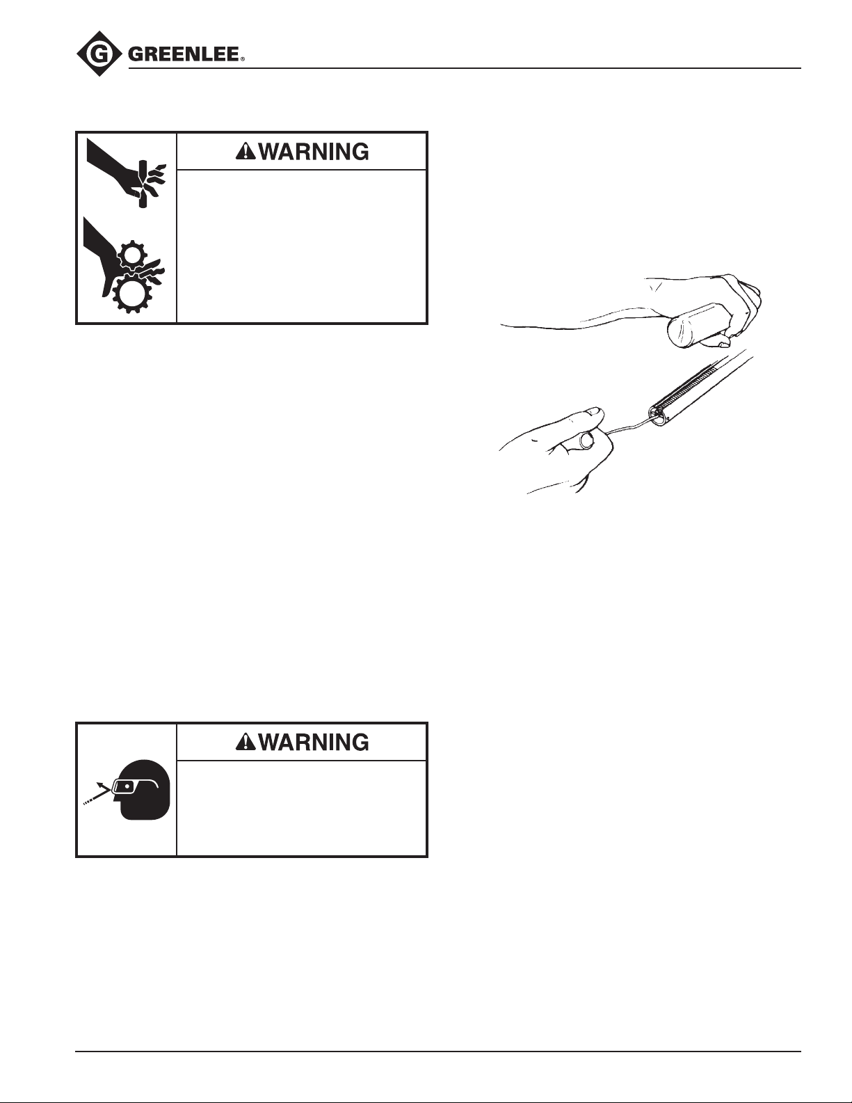
1. Clamp the long handle (31) into a vise with the short
handle (53) parallel to the oor and with the head
pointing away from you.
2. Remove the rubber grip (43).
3. Unhook the spring (39) from the pin (40) in the short
handle (53) (see Figure 1).
Figure 1
Disassembly
1. Clamp the long handle (31) into a vise with the short
handle (53) parallel to the oor and with the head
pointing away from you.
2. Remove the rubber grip (43).
3. Unhook the spring (39) from the pin (40) in the short
handle (53) (see Figure 1).
4. Loosen nut (20) from bolt (19) using 7/16" wrenches.
5. Remove bolt and snubber (16).
6. Remove tool from vise.
7. Unhook two closing springs (15).
8. Remove bolt (19) and nut (20) and snubber (16).
9. Remove cutterhead from handles using 9/16"
wrenches.
10. Remove right handle assembly, with the chain and
spring still attached, from the left handle.
11. Remove retaining ring (54) from sprocket pin (51).
12. Remove sprocket pin (51).
13. Remove 2 side plates (55), sprocket (56), washer
(57), pin (23), detent pawl (28), and spring (36).
14. Clean all parts thoroughly with solvent.
Greenlee / A Textron Company 4455 Boeing Dr. • Rockford, IL 61109-2988 USA • 815-397-7070
5
Page 6
Maintenance (cont’d)
Assembly
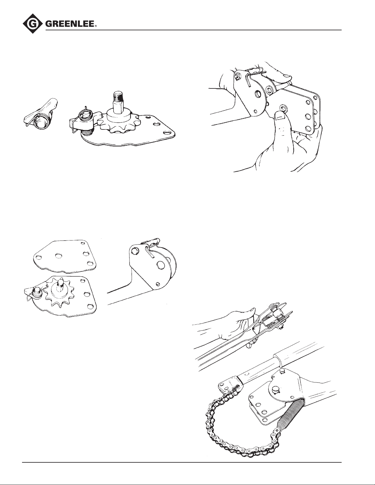
1. Assemble sprocket pin (51) to one side plate (55).
Lay this assembly on the bench with the notched
edge of the plate nearest you (see Figure 3).
Figure 3
Figure 2
2. Apply a light lm of grease to the shank of the pin.
3. Slide sprocket (56) onto pin.
4. Apply grease to the detent pin (23) and slide into
the detent pawl. Place the detent spring (36) onto
the pin making sure the spring ends have not been
bent out of shape. The cross arm of the spring goes
under the at side of the arrow shaped point of the
detent pawl (see Figure 2).
5. Assemble one end of detent pin (23) into the hole on
side plate (55) and engage the rounded end of the
sprocket (56) (see Figure 3).
Figure 4
Figure 5
756 and 757 Ratchet Cable Cutters
Figure 6
10. Secure sprocket pin with retaining rings (54).
(This assembly must be free to pivot freely.)
11. With a small hook tool, reach up from the bottom
of the assembly, between the plates and hook the
ends of the detent spring into their respective holes
(see Figure 7). Check to be sure spring loops are not
caught between the pin and the side plate.
12. Remove the 1/8" pin from under the pawl and
engage the drive pawl with sprocket (56).
13. Remove the handle from the vise.
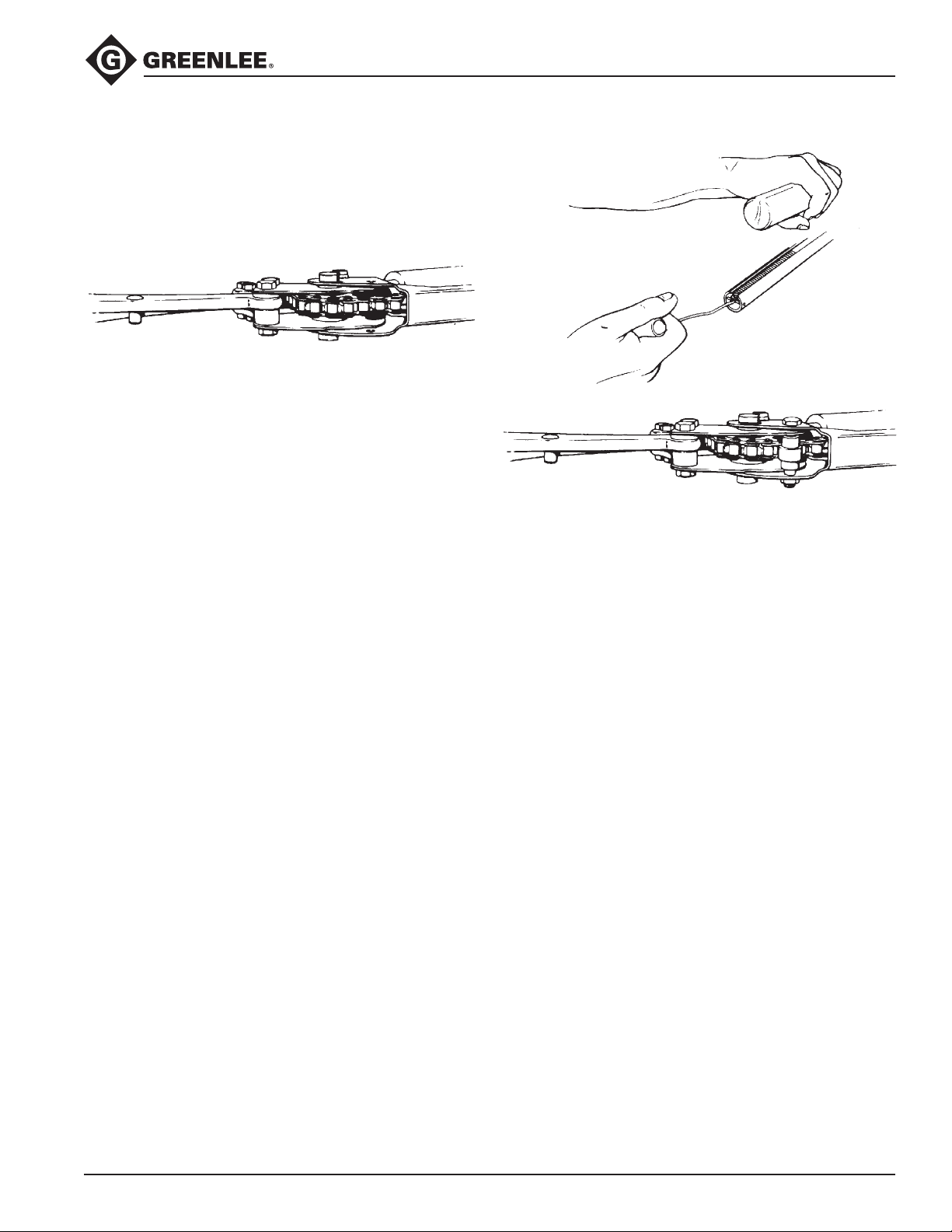
14. Hook the longer loop on the chain spring (39) onto
the free end of the chain (38). Lay the left and right
handles on the bench. The drive pawl is located
in the left handle. The chain is attached to the
right handle. Feed the spring on the chain over the
sprocket and into the left handle (see Figure 9).
Figure 7
6. Match up the second plate (55) with the rst, and
place over the detent pin and pivot bolt. Do not
insert spring ends into plates at this point (see
Figure 4).
7. Hold the left handle (53) in vise with the drive pawl
facing up and the handle pointing to your left (see
Figure 5). Pull the drive pawl up, moving counterclockwise, and insert a 1/8" pin (rod or nail) through
the small holes in the plates near the drive pawl to
hold it in a horizontal position (see Figure 5).
8. Grasp the side plate assembly rmly with the
notched edges of the plate facing down. While
holding tightly between ngers, remove the sprocket
pin (see Figure 6).
9. Carefully insert the plate assembly into the left
handle between the washers (57). Align the holes
and slide the sprocket pin into position.
Greenlee / A Textron Company 4455 Boeing Dr. • Rockford, IL 61109-2988 USA • 815-397-7070
6
Figure 8
Page 7
Maintenance (cont’d)
15. With handles remaining in this position, assemble
the cutting head to the left handle. The thick spacer
(25) goes between the blade holders (see Figure 9).
Use the longer bolt (12) and nut (26) and tighten
securely.
Figure 9
16. Assemble the other side of the head to the right
handle using bolts (12), nuts (26) and washer (7).
Tighten securely.
17. Hook open end of closing spring (15) into holes in
handle (53) so that closed loops will be against side
plates (55).
18. Insert bolt (19) through closed loop on one of the
springs (15) and insert through 1/4 inch hole in side
plate (55). At the same time assemble snubber (16)
and slide bolt through snubber.
19. Assemble other spring (15) onto bolt and assemble
nut onto bolt.
20. Tighten nut approximately one thread beyond end
of bolt.
21. Hook the chain spring (39) over pin at end of the left
handle (see Figure 10).
22. Assemble snubber (16) and bolt (19) to handle.
Assemble nut and tighten so as not to bind assembly (see Figure 11).
756 and 757 Ratchet Cable Cutters
Figure 10
Figure 11
23. Check operation of the tool by opening and closing.
If operation is satisfactory, proceed to next step.
24. Assemble grip to left handle (53). There is a “key”
in the interior of the grip. Align this key with the
slot in the left (or ratcheting) handle, and push the
grip over the handle. No lubrication or adhesive is
needed. Assemble clamp to grip and tighten.
If sliding a replacement grip over a replacement
right handle (31), spread a small amount of soapy
water over the handle to ease assembly. It will
eventually dry out and allow a solid adhesion to the
handle. The grip requires pounding to t over the
handle.
Greenlee / A Textron Company 4455 Boeing Dr. • Rockford, IL 61109-2988 USA • 815-397-7070
7
Page 8
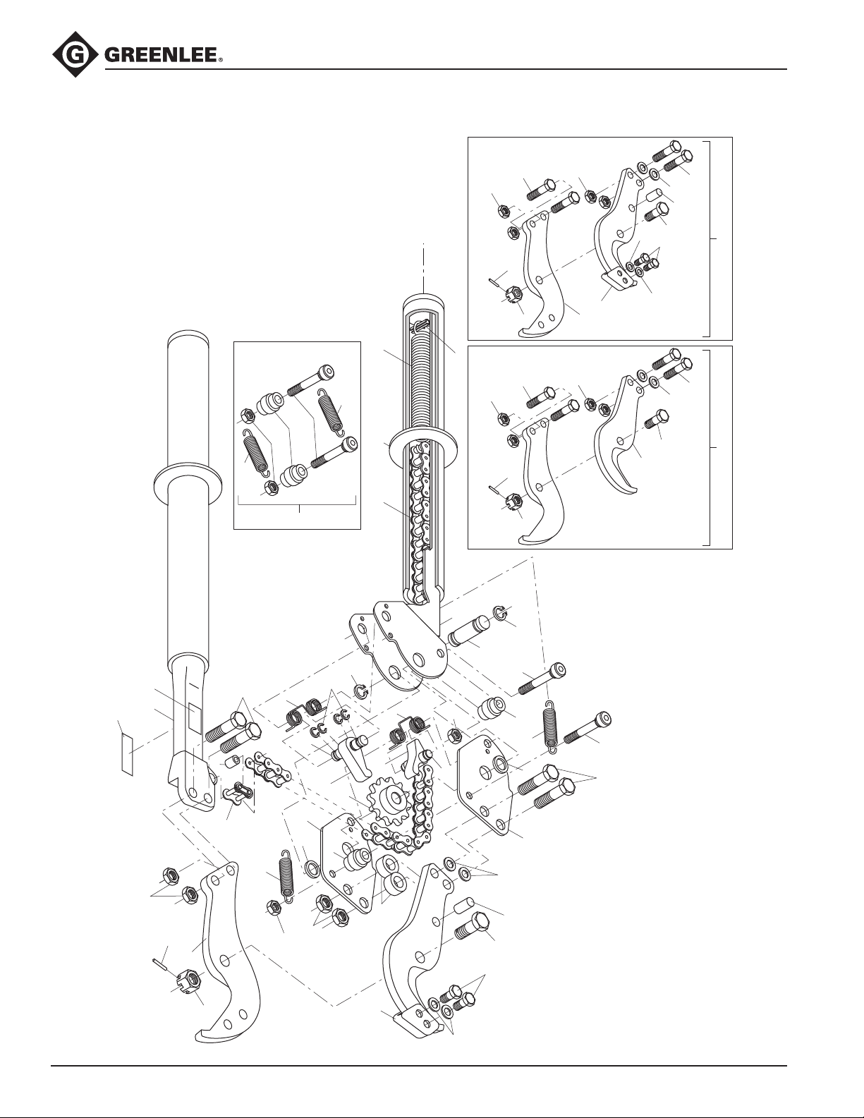
Illustration
756 and 757 Ratchet Cable Cutters
Repair Kit
15
12
26
6
757 Cutter Head
5
40
12
15
19
16
20
13
43
38 39
26
6
756 Cutter Head
5
26
46
10
8
26
2
12
24
59
4
11
46
24
4
7
12
1
31B
26
31A
31
53
54
51
54
12
30
29
6
8
5
33
15
20
37
36
52
28
34
56
55
57
16
25
26
10
20
23
19
16
15
57
55
24
59
4
11
19
12
46
Greenlee / A Textron Company 4455 Boeing Dr. • Rockford, IL 61109-2988 USA • 815-397-7070
8
Page 9

756 and 757 Ratchet Cable Cutters
Parts List
756 (for serial codes after ZDHA)
Key Part No. Description Qty
2 Blade (included in 50341880 kit) .............................................................. 2
4 Bolt, 1/2-20 x 1-1/4 pivot .......................................................................... 1
5 Nut, 1/2-20 hex slotted ............................................................................. 1
6 Pin, ø3/32 x 3/4 drive ................................................................................ 1
12 Screw, 3/8-24 x 1-1/2 hex head cap ........................................................ 4
15 Spring, extension ...................................................................................... 2
16 Snubber, chain .......................................................................................... 2
19 Screw, 1/4-20 x 1-3/4 socket head cap (order with item 20) .................... 2
20 Nut, 1/4-20 hex lock (order with item 19) ................................................. 2
23 50341677 Pin, detent ................................................................................................. 1
24 Spacer, thin ............................................................................................... 2
25 50341693 Spacer ....................................................................................................... 2
26 Nut, 3/8-24 hex lock ................................................................................. 4
28 50341650 Pawl, detent .............................................................................................. 1
29 90527879 Link, chain connector (included with item 38)
30 50341596 Bushing ..................................................................................................... 1
31 50362119 Right handle unit (includes items 31A, 31B, 43) ....................................... 1
31A 50021621 Decal, identication, Model 756 ............................................................... 1
31B 50021630 Decal, warning .......................................................................................... 1
33 50341758 Spring, drive pawl ..................................................................................... 1
34 50341642 Pawl, drive ................................................................................................. 1
36 50341766 Spring, torsion ........................................................................................... 1
37 Ring, retainer ............................................................................................. 4
38 50341723 Chain (includes item 24) ............................................................................ 1
39 50341774 Spring, chain ............................................................................................. 1
40 Rollpin, ø1/8 x 1-1/8 ................................................................................. 1
43 50340832 Grip, handle............................................................................................... 2
51 Pin, sprocket ............................................................................................. 1
52 Pin, pawl drive ........................................................................................... 1
53 Handle, left ................................................................................................ 1
54 Ring, retaining ........................................................................................... 2
55 Side plate .................................................................................................. 2
56 Sprocket .................................................................................................... 1
57 Washer, 5/8 at ......................................................................................... 2
Greenlee / A Textron Company 4455 Boeing Dr. • Rockford, IL 61109-2988 USA • 815-397-7070
9
Page 10

756 and 757 Ratchet Cable Cutters
Repair Parts List
756 (for serial codes after ZDHA)
Key Part No. Description
1 50341880 756 cutterhead
(includes items 2, 4, 5, 6, 12, 24, 26)
Recommend replacing pivot bolt and nut whenever blades are replaced
13 50341898 756 and 757 repair kit
(includes items 15, 16, 19, 20)
47* Nut, 7/16-20 hex slotted
48* Bolt, 7/16-20 x 1-1/8 hex head
50 50356410 756 pivot bolt assembly
(includes items 4, 5, 6, 47, 48)
*Use 7/16" bolt and nut only with 5/16" thick blades (earlier model)
Ratchet Mechanism Upgrade Kit
756 (upgrades ratchet mechanism on cutters with no serial code)
Key Part No. Description
58 50372327 Ratchet mechanism
(includes items 37, 51, 52, 53, 54, 55, 56, 57)
Greenlee / A Textron Company 4455 Boeing Dr. • Rockford, IL 61109-2988 USA • 815-397-7070
10
Page 11

756 and 757 Ratchet Cable Cutters
Parts List
757 (for serial codes after ZDHA)
Key Part No. Description Qty
4 Bolt, 1/2-20 x 1-1/4 pivot .......................................................................... 1
5 Nut, 1/2-20 hex slotted ............................................................................. 1
6 Pin, ø3/32 x 3/4 drive ................................................................................ 1
8 Blade unit (included in 50341871 kit) ........................................................ 2
10 Keeper unit ................................................................................................ 1
11 Screw, 5/16-18 x 1/2 hex cap ................................................................... 2
12 Screw, 3/8-24 x 1-1/2 hex head cap ........................................................ 4
15 Spring, extension ...................................................................................... 2
16 Snubber, chain .......................................................................................... 2
19 Screw, 1/4-20 x 1-3/4 socket head cap (order with item 20) .................... 2
20 Nut, 1/4-20 hex lock (order with item 19) ................................................. 2
23 50341677 Pin, detent ................................................................................................. 1
24 Spacer, thin ............................................................................................... 2
25 50341693 Spacer ....................................................................................................... 2
26 Nut, 3/8-24 hex lock ................................................................................. 4
28 50341650 Pawl, detent .............................................................................................. 1
29 90527879 Link, chain connector (included with item 38)
30 50341596 Bushing ..................................................................................................... 1
31 50362119 Right handle unit (includes items 31A, 31B, 43) ....................................... 1
31A 50021648 Decal, identication, Model 757 ............................................................... 1
31B 50021630 Decal, warning .......................................................................................... 1
33 50341758 Spring, drive pawl ..................................................................................... 1
34 50341642 Pawl, drive ................................................................................................. 1
36 50341766 Spring, torsion ........................................................................................... 1
37 Ring, retainer ............................................................................................. 4
38 50341723 Chain (includes item 29) ............................................................................ 1
39 50341774 Spring, chain ............................................................................................. 1
40 Rollpin, ø1/8 x 1-1/8 ................................................................................. 1
43 50340832 Grip, handle............................................................................................... 2
46 Washer, 5/16 int. tooth lock ...................................................................... 2
51 Pin, sprocket ............................................................................................. 1
52 Pin, pawl drive ........................................................................................... 1
53 Handle, left ................................................................................................ 1
54 Ring, retaining ........................................................................................... 2
55 Side plate .................................................................................................. 2
56 Sprocket .................................................................................................... 1
57 Washer, 5/8 at ......................................................................................... 2
59 Pin, ø5/16 x 3/4 stop ................................................................................. 1
Greenlee / A Textron Company 4455 Boeing Dr. • Rockford, IL 61109-2988 USA • 815-397-7070
11
Page 12
756 and 757 Ratchet Cable Cutters
Repair Parts List
757 (for serial codes after ZDHA)
Key Part No. Description
7 50341871 757 cutterhead
(includes items 4, 5, 6, 8, 10, 11, 12, 24, 46, 59)
13 50341898 756 and 757 repair kit
(includes items 15, 16, 19, 20)
49* Washer, 1/2 at
50 50356410 757 pivot bolt assembly
(includes items 4, 5, 6, 49)
*Use washer with 5/16" thick blades (earlier model)
Ratchet Mechanism Upgrade Kit
757 (upgrades ratchet mechanism on cutters with no serial code)
Key Part No. Description
58 50372327 Ratchet mechanism
(includes items 37, 51, 52, 53, 54, 55, 56, 57)
4455 Boeing Drive • Rockford, IL 61109-2988 • USA • 815-397-7070
An ISO 9001 Company • Greenlee Textron Inc. is a subsidiary of Textron Inc.
www.greenlee.com
USA Tel: 800-435-0786
Fax: 800-451-2632
Canada Tel: 800-435-0786
Fax: 800-524-2853
International Tel: +1-815-397-7070
Fax: +1-815-397-9247
 Loading...