

Page 1
INSTRUCTION MANUAL
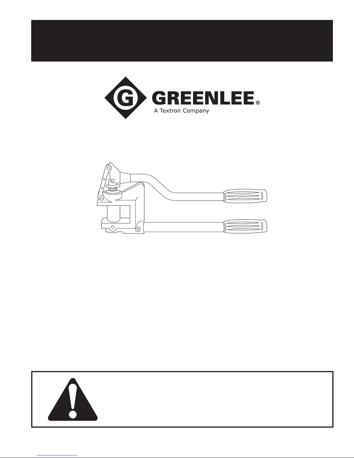
709 and 710
Stud Punches
Read and understand all of the instructions and
safety information in this manual before operating
of servicing this tool.
99975106 © 2007 Greenlee Textron Inc. IM 888 REV 21 3/07
Page 2
709 and 710 Stud Punches
IMPORTANT SAFETY INFORMATION
SAFETY
ALERT
SYMBOL
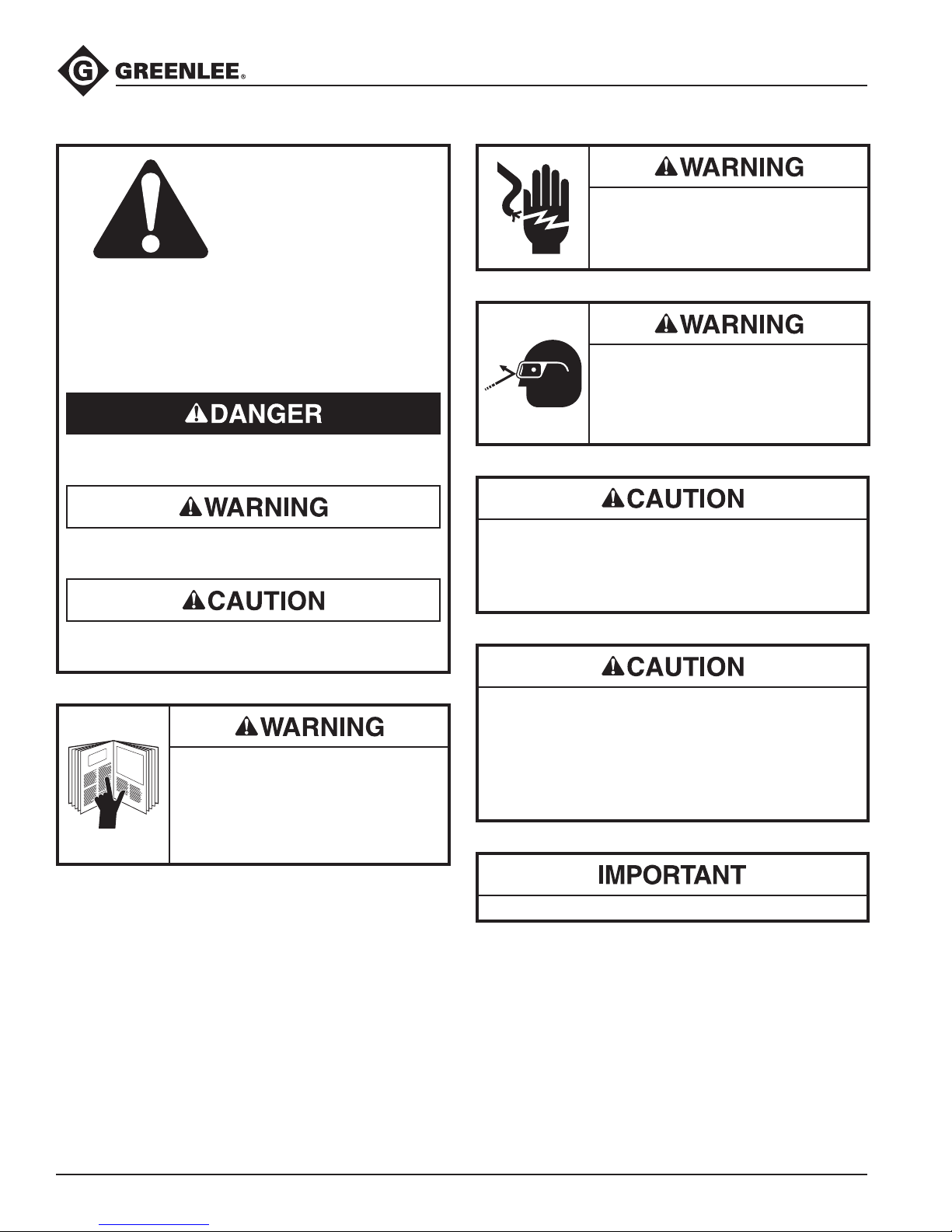
This symbol is used to call your attention to hazards
or unsafe practices which could result in an injury or
property damage. The signal word, dened below,
indicates the severity of the hazard. The message
after the signal word provides information for
preventing or avoiding the hazard.
Immediate hazards which, if not avoided, WILL result
in severe injury or death.
Hazards which, if not avoided, COULD result in
severe injury or death.
Electric shock hazard:
This is not an insulated tool. Contact
with live circuits could result in severe
injury or death.
Wear eye protection when using
this tool.
Failure to wear eye protection could
result in serious eye injury from ying
debris.
Do not add extensions (cheaters) to the handles.
Using excessive force may result in injury or damage
to the tool. If excessive force is required to complete
a punch, verify that the type and thickness of material
do not exceed the capacity of the tool.
Hazards or unsafe practices which, if not avoided,
MAY result in injury or property damage.
Read and understand all of the
instructions and safety information
in this manual before operating or
servicing this tool.
Failure to observe this warning could
result in severe injury or death.
Inspect the tool prior to use. Replace worn,
•
damaged or missing components with Greenlee
replacement parts. A damaged or improperly
assembled tool may break.
Use this tool for manufacturer’s intended use only.
•
Use other than that which is described in this
manual may result in injury or damage to the tool.
Do not use on heavier than 20 gauge mild steel.
All specications are nominal and may change as design
improvements occur. Greenlee Textron Inc. shall not be liable for
damages resulting from misapplication or misuse of its products.
Greenlee / A Textron Company 4455 Boeing Dr. • Rockford, IL 61109-2988 USA • 815-397-7070
KEEP THIS MANUAL
2
Page 3

709 and 710 Stud Punches
Description
Greenlee Stud Punches are intended to punch round
holes in 20 gauge steel studs. The 709 tool punches
a 22.5 mm (7/8") diameter hole; the 710 tool punches a
34.1 mm (1-11/32") hole.
Safety
Safety is essential in the use and maintenance of
Greenlee tools and equipment. This manual and any
markings on the tool provide information for avoiding
hazards and unsafe practices related to the use of this
tool. Observe all of the safety information provided.
Purpose of this Manual
This manual is intended to familiarize all personnel with
the safe operation and maintenance procedures for the
following Greenlee tools:
709 Stud Punch
710 Stud Punch
Keep this manual available to all personnel.
Replacement manuals are available upon request at no
charge at www.greenlee.com.
Operation
Position the punch on the metal stud. Squeeze the
handles together. The slug will fall free when the hole is
complete.
Note: This tool will punch to its rated capacity with
approximately 56 pounds of handle force. If excessive
force is required, stop and inspect the tool and the
material.
Bushings
Bushings are available for the holes punched by the
Stud Punches. Bushings protect wire insulation from the
sharp edges of the metal stud.
Use Greenlee 711 Bushings for 22.5 mm (7/8") holes
•
made by the 709 Stud Punch.
Use 712 Bushings for 34.1 mm (1-11/32") holes made
•
by the 710.
Maintenance
Lubricate all moving parts with a lightweight oil.
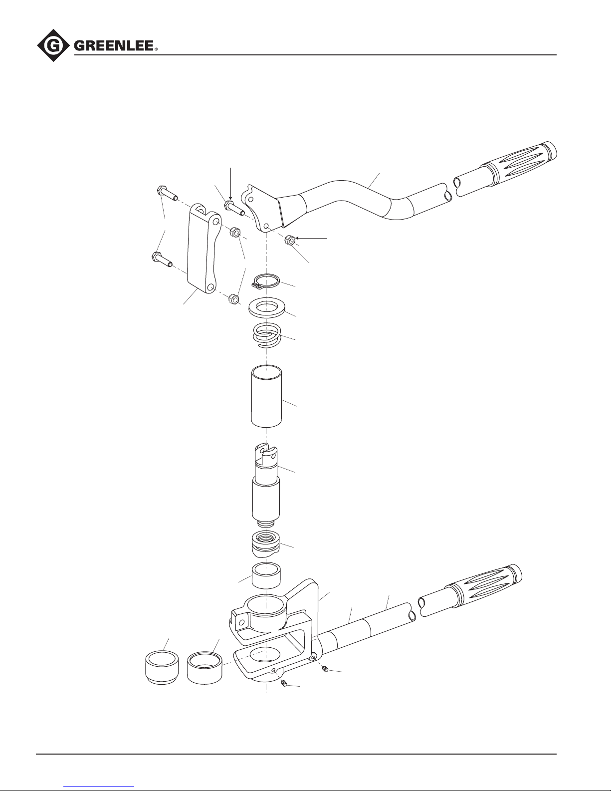
To replace the punch, refer to the illustration on the next
page, and follow this procedure:
Remove the locknut (A) from the pivot bolt (B),
1.
and then remove the pivot bolt from the punch
holder (8).
Remove the entire punch holder shaft and sleeve
2.
from the C-frame.
Depress the sleeve and unscrew the punch from the
3.
punch holder.
Greenlee / A Textron Company 4455 Boeing Dr. • Rockford, IL 61109-2988 USA • 815-397-7070
3
Page 4
Illustration
1
5
6
9
7
8
12
15
14
21
17
18
13
2
20
20
4
4
A
B
25
24
709 and 710 Stud Punches
Greenlee / A Textron Company 4455 Boeing Dr. • Rockford, IL 61109-2988 USA • 815-397-7070
4
Page 5

Parts List
709 and 710 Stud Punches
Key Part No. Part No. Description Qty.
709 710
50222805 50212850 Stud punch complete
1 52027489 52027489 Lever unit ...................................................................................... 1
2 Link (see below for service parts) ................................................. 1
4 Locknuts ....................................................................................... 3
5 50213032 50213032 Washer, at .968 x 1.62 x .062 .....................................................1
6 50215574 50215574 Spring, compression ....................................................................1
7 52026024 Sleeve ...........................................................................................1
8 50222821 Holder, punch ............................................................................... 1
9 90513614 90513614 Retaining ring, .865
Truarc #5100-93-S-PP .................................................................1
12 50040065 50248235 Punch, conduit .............................................................................1
13 50222864 50212974 Die ................................................................................................1
14 52027490 52027490 Handle, green ...............................................................................1
15 C-Frame unit ................................................................................1
17 90507649 Screw, set, 1/4–20 x .375 socket w/locking patch .......................2
17 90507649 Screw, set, 1/4–20 x .375 socket w/locking patch .......................1
18 90506170 Screw, set, 1/4–20 x .250 socket w/locking patch .......................1
20 Bolts, pivot, 1/4 x 20 ....................................................................3
21 50053809 50010085 Decal, identication ...................................................................... 1
24 52024666 — Bushing, die ..................................................................................1
25 50213016 50213016 Bushing ........................................................................................ 1
Repair Kits List
Part No. Description
50060155 Pin kit (includes items 4 and 20)
50059327 Link kit (includes items 2, 4 and 20)
*** 52027488 Service aluminum handle
** 52026022 Sliding mechanism service kit (includes items 7 and 8)
* 52026024 Sleeve (O.D. = 1.435") (includes item 7)
* 50222848 Service sleeve (O.D. = 1.110")
** 50222821 Punch holder
* Check O.D. for correct sleeve size.
** Use one at washer (50213032), as shown in the illustration,
when replacing the punch holders.
*** Aluminum, unpainted handle for tools prior to 04/2007
709 and 710
710 Only
709 Only
Greenlee / A Textron Company 4455 Boeing Dr. • Rockford, IL 61109-2988 USA • 815-397-7070
5
Page 6

USA 800-435-0786 Fax: 800-451-2632
815-397-7070 Fax: 815-397-1865
Canada 800-435-0786 Fax: 800-524-2853
International +1-815-397-7070 Fax: +1-815-397-9247
4455 Boeing Drive • Rockford, IL 61109-2988 • USA • 815-397-7070
An ISO 9001 Company
•
Greenlee Textron Inc. is a subsidiary of Textron Inc.
www.greenlee.com
 Loading...