

Page 1
INSTRUCTION MANUAL
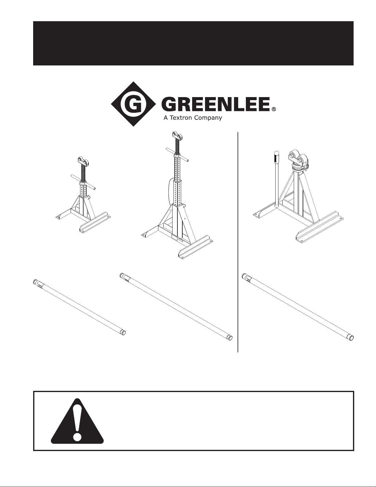
687 683 656
647 684 657
Reel Stands and Spindles
Read and understand all of the instructions and
safety information in this manual before operating
or servicing this tool.
52040972 REV 5 © 2015 Greenlee Textron Inc. 12/15
Find Quality Products Online at: [email protected]
www.GlobalTestSupply.com
Page 2

Reel Stands and Spindles
Greenlee / A Textron Company
Table of Contents
Description
Description .................................................................... 2
Safety ............................................................................ 2
Purpose of this Manual ................................................. 2
Important Safety Information ........................................ 3
Specications ................................................................ 4
Repair Parts ................................................................... 4
Maintenance .................................................................. 4
Operation ....................................................................... 4
The Greenlee 687, 683 and 656 Reel Stands and
647, 684 and 657 Reel Spindles are intended for
dispensing of cable from cable reels.
Safety
Safety is essential in the use and maintenance of
Greenlee tools and equipment. This manual and any
markings on the tool provide information for avoiding
hazards and unsafe practices related to the use of this
tool. Observe all of the safety information provided.
Purpose of this Manual
This manual is intended to familiarize all personnel with
the safe operation and maintenance procedures for the
following Greenlee tools:
687 Reel Stand
683 Reel Stand
656 Reel Stand
647 Reel Spindle
684 Reel Spindle
657 Reel Spindle
Keep this manual available to all personnel.
Replacement manuals are available upon request at
All specications are nominal and may change as design
improvements occur. Greenlee Textron Inc. shall not be liable for
damages resulting from misapplication or misuse of its products.
® Registered: The color green for material handling equipment is a
registered trademark of Textron Innovations Inc.
MOLYKOTE is a registered trademark of Dow Corning.
KEEP THIS MANUAL
2
Find Quality Products Online at: [email protected]
www.GlobalTestSupply.com
Page 3
Reel Stands and Spindles
Greenlee / A Textron Company
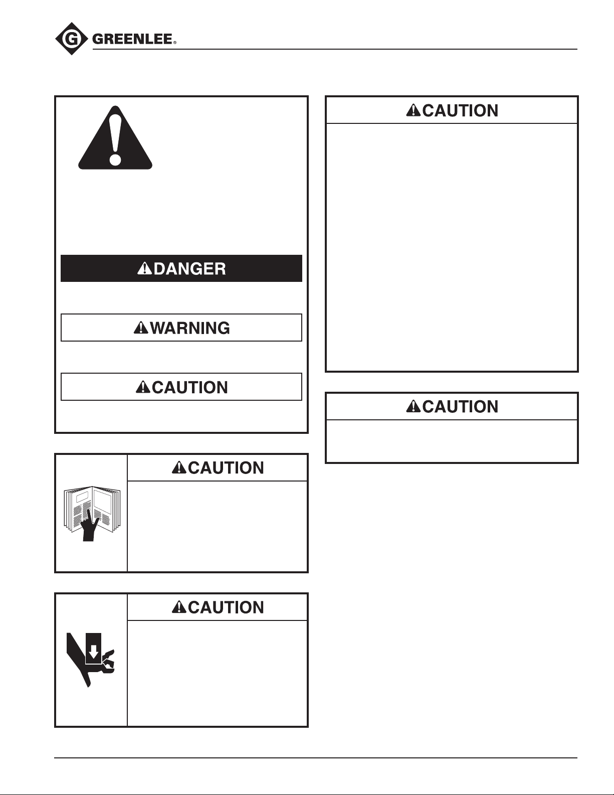
IMPORTANT SAFETY INFORMATION
SAFETY
ALERT
SYMBOL
This symbol is used to call your attention to
hazards or unsafe practices which could result in
an injury or property damage. The signal word,
dened below, indicates the severity of the hazard.
The message after the signal word provides information for preventing or avoiding the hazard.
Immediate hazards which, if not avoided, WILL
result in severe injury or death.
Hazards which, if not avoided, COULD result in
severe injury or death.
• Make sure bystanders are clear of the work area
when loading, unloading or dispensing cable.
Nearby personnel can be injured if a cable reel
escapes.
• Do not use the reel roller for cable with damaged
reels. Damaged reels may not roll freely and may
be pulled off the reel roller.
• Cable reels must be chocked at all contact points
with the ground to prevent movement during setup.
• The proper Greenlee spindle is required for safe
operation of this tool. Do not use anything else—
substitutes may not support the cable reel or may
fall off the reel stand.
• Never attach casters or wheels to a Greenlee reel
stand.
• Use only on a hard, at, level surface.
• Do not exceed the rated capacity of this tool.
Failure to observe these precautions may result in
injury or property damage.
Hazards or unsafe practices which, if not avoided,
MAY result in injury or property damage.
Read and understand all of the
instructions and safety information
in this manual before operating or
servicing this tool.
Failure to observe this precaution
may result in injury or property
damage.
• Keep hands and feet clear when
loading and unloading cable reels.
• Cable reels must be chocked at all
contact points with the ground to
prevent movement during setup.
Failure to observe these precautions
may result in injury or property
damage.
Use this tool for manufacturer’s intended use only.
Use other than that which is described in this
manuals may result in injury or property damage.
Note: Keep all decals clean and legible, and replace
when necessary.
3
Find Quality Products Online at: [email protected]
www.GlobalTestSupply.com
Page 4
Reel Stands and Spindles
Greenlee / A Textron Company
Specifications
Cat.
No.
687
683
656
Capacity
2500 lb ea
(1134 kg)
3750 lb ea
(1701 kg)
Max
Height
28"
(711 mm)
54"
(1372 mm)
46-5/8"
(1184 mm)
Base
Dimensions
15" x 15"
(381 x 381 mm)
21" x 24"
(533 x 610 mm)
23" x 24.5"
(584 x 622 mm)
Repair Parts
52078241................. Ratchet assembly (656)
50302914................. Handle with grip (656)
50302965................. Pawl (656)
90532759................. Spring (656)
50255916................. Stop pin (687-1, 683-2)
Weight
22 lb
(10 kg)
40 lb
(18 kg)
86 lb
(39 kg)
Max Reel
Diameter
56"
(1422 mm)
96"
(2438 mm)
90"
(2286 mm)
Spindle Capacity Size Weight
647
684
657
6000 lb
(2722 kg)
5000 lb
(2268 kg)
7500 lb
(3402 kg)
Ø2-3/8" x 62"
(60 x 1575 mm)
Ø2-3/8" x 76"
(60 x 1930 mm)
Ø3-1/2" x 100"
(89 x 2540 mm)
42 lb
(19 kg)
50 lb
(23 kg)
124 lb
(56 kg)
Max Reel
Width
47"
(1194 mm)
61"
(1549 mm)
88"
(2235 mm)
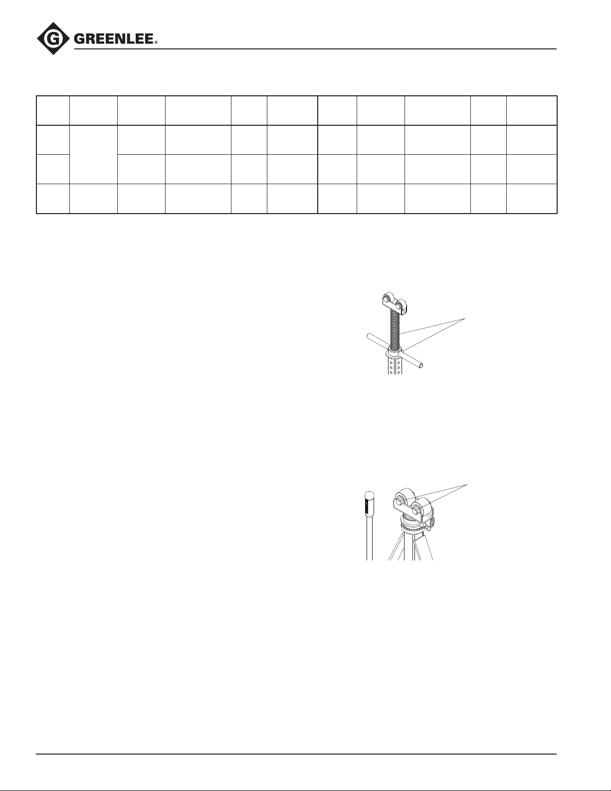
Maintenance Procedure
687 and 683
Grease
To maximize efciency and extend the life of the
product, apply a thin coat of grease to the threaded
shaft and a moderate amount of grease between the
thrust washer and underside of the handle. For best
results, apply grease before each use.
656
Grease
Zerks
To maximize efciency and extend the life of the
product, re-grease the rollers on the reel stand using the
grease zerks found in the center of the roller axles.
Before each use apply a generous coat of an extreme
pressure lubricant such as a MOLYKOTE® G-n type
paste to the threaded shaft. Keep the components free
of debris.
4
Find Quality Products Online at: [email protected]
www.GlobalTestSupply.com
Page 5
Reel Stands and Spindles
Greenlee / A Textron Company
Operation
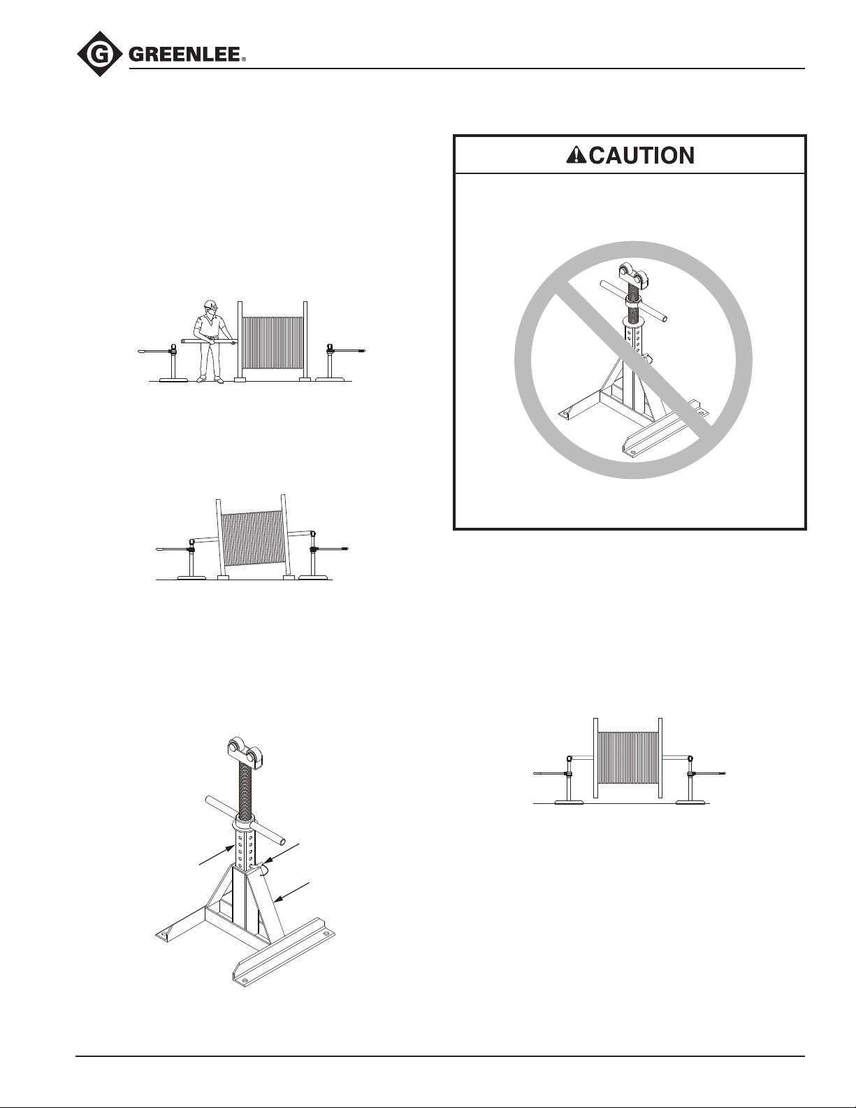
1. Two alike reel stands and one Greenlee reel
stand spindle are required for a complete setup.
(The 687 and 683 reel stands must be used with
only the 647 or 684 spindles. The 656 reel stand
must be used with only the 657 spindle.)
2. Make sure the cable reel is chocked to prevent
movement during setup.
3. Position the spindle through the center holes of the
cable reel. (Fig. 1)
Figure 1
4. Position reel stands under each end of the spindle
so the reel stand rollers are aligned within and in
contact with the spindle grooves. (Fig. 2)
Never support a load with handle positioned as
shown below. Handle must always contact support
washer as shown in Figure 3.
Figure 2
Note: The 687 and 683 reel stands may require use
of the quick extend feature. Manually lift the telescoping square tubing to desired height and use the
pin provided by inserting through both sides of the
square tubing. The pin must rest on top of the base
to prevent downward movement. (Fig. 3)
Pin
Tube
Base
Failure to observe this precaution may result in injury
or property damage.
5. Turn the reel stand handle clockwise to extend one
reel stand until the cable reel clears the ground.
(Fig.2)
Note: The 656 requires the handle to be fully
threaded into the handle ratchet assembly and the
ratchet pawl to be set so the clicking is evident
when the handle is turned counterclockwise.
6. Turn the other reel stand handle until the spindle is
level and the cable reel rotates freely. (Fig. 4)
Figure 4
7. When nished dispensing cable, the cable reel
should be lowered in the reverse manner as
described above.
Figure 3
5
Find Quality Products Online at: [email protected]
www.GlobalTestSupply.com
Page 6

 Loading...