

Page 1
INSTRUCTION MANUAL
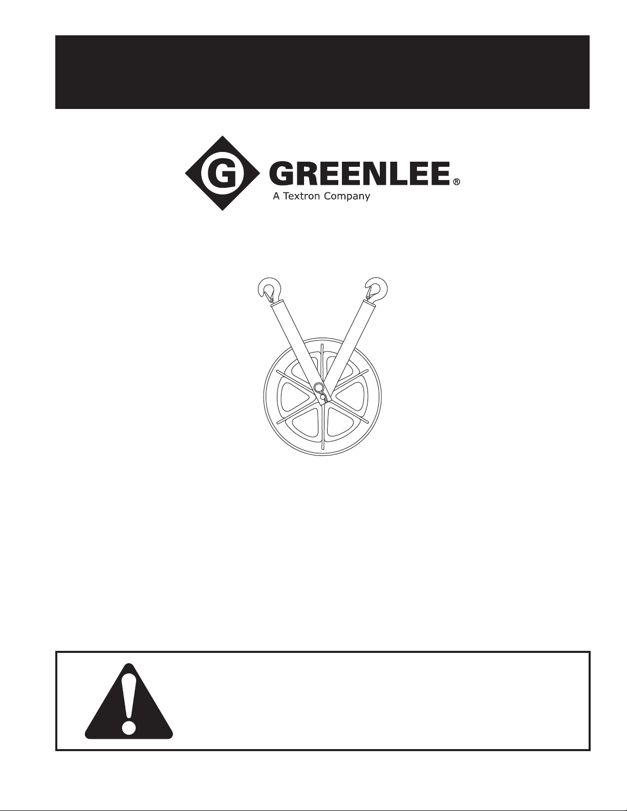
Hook Sheaves
639, 650, 651, 652, and 653
8012, 8018, and 8024
Read and understand all of the instructions and
safety information in this manual before operating
or servicing this tool.
52056646 REV 2 © 2015 Greenlee Textron Inc. 9/15
Find Quality Products Online at: [email protected]
www.GlobalTestSupply.com
Page 2

Hook Sheaves
Table of Contents
Description .................................................................... 2
Safety ............................................................................ 2
Purpose of this Manual ................................................. 2
Important Safety Information ........................................ 3
Hook Load ..................................................................4–7
Some Hook Loads Illustrated .................................... 5
Calculating the Hook Load .....................................6–7
Hoist Hook ..................................................................... 8
Hook Latch Kit ............................................................... 9
Illustrations and Parts Lists ....................................10–11
639, 650, 651, 652, and 653 .................................... 10
8012, 8018, and 8024 .............................................. 11
Description
Greenlee Hook Sheaves are used to change the
direction of a rope or cable while installing cable in
conduit or raceway.
They may also be used to change the direction of the
cable puller tailing rope to allow the operator to stand
away from the line of the high tension pulling rope
approaching the puller.
Safety
Safety is essential in the use and maintenance of
Greenlee tools and equipment. This instruction manual
and any markings on the tool provide information for
avoiding hazards and unsafe practices related to the
use of this tool. Observe all of the safety information
provided.
Purpose of this Manual
This manual is intended to familiarize all personnel with
the safe operation and maintenance procedures for the
following Greenlee tools:
Hook Sheaves:
639, 650, 651, 652, and 653
8012, 8018, and 8024
Keep this manual available to all personnel.
Replacement manuals are available upon request at
no charge
All specications are nominal and may change as design
improvements occur. Greenlee Textron Inc. shall not be liable for
damages resulting from misapplication or misuse of its products.
Tugger is a registered trademark of Textron Innovations Inc.
KEEP THIS MANUAL
Greenlee / A Textron Company
Find Quality Products Online at: [email protected]
www.GlobalTestSupply.com
2
Page 3
IMPORTANT SAFETY INFORMATION
SAFETY
ALERT
SYMBOL
This symbol is used to call your attention to hazards
or unsafe practices which could result in an injury or
property damage. The signal word, dened below,
indicates the severity of the hazard. The message
after the signal word provides information for preventing or avoiding the hazard.
Immediate hazards which, if not avoided, WILL result
in severe injury or death.
Hook Sheaves
For use in cable pulling only. Do not use for lifting
personnel or equipment.
Failure to observe this warning could result in severe
injury or death.
Inspect all anchorings, structural
supports and hook sheaves. Verify
that they will safely withstand up to
twice the cable puller’s maximum
pulling capacity.
Any component that cannot withstand this much force could break
and strike nearby personnel, causing
severe injury or death.
Hazards which, if not avoided, COULD result in
severe injury or death.
Hazards or unsafe practices which, if not avoided,
MAY result in injury or property damage.
Read and understand all of the
instructions and safety information
in this manual as well as the manual
supplied with the cable puller before
operating or servicing this tool.
Failure to observe this warning could
result in severe injury or death.
Wear eye protection when operating
this tool.
Failure to wear eye protection could
result in serious eye injury from ying
debris.
The maximum force the cable puller will exert on the
hook is twice its capacity. Assume that twice the
cable puller’s capacity will be exerted on every hook
sheave and structural support.
Failure to observe this warning could result in severe
injury or death.
Consult the cable manufacturer’s specications for
minimum bending radius and other information. Using
sheaves that are too small can damage the cable.
Failure to observe this precaution may result in
property damage.
Note: Keep all decals clean and legible, and replace
when necessary.
Greenlee / A Textron Company
Find Quality Products Online at: [email protected]
www.GlobalTestSupply.com
3
Page 4
Hook Load
Hook Sheaves
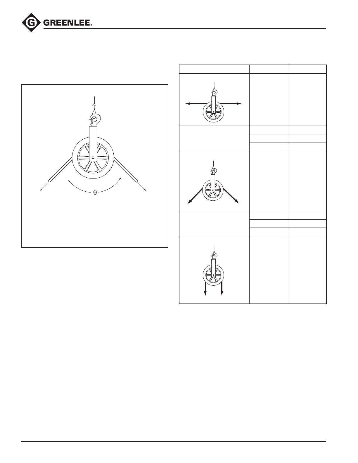
Two variables interact with the sheave to produce a
resultant (total) force, or hook load. This load, represented by R in the formulas and illustrations, is exerted
on the hook, anchoring, and structural support.
R
T
R = the resultant force, or hook load; this force is
exerted on the hook, anchoring, and structural
support
e = the angle of change in rope direction
T = the tension exerted on the rope by the cable
puller
T
Reference Table
Illustration
R = 0
TT
R = 1.41 x T
TT
R = 2 x T
e
180° 0
150° 0.52 x T
135° 0.77 x T
120° 1 x T
90° 1.41 x T
60° 1.73 x T
45° 1.85 x T
30° 1.93 x T
R
Sheave Forces
0° 2 x T
TT
Greenlee / A Textron Company
Find Quality Products Online at: [email protected]
www.GlobalTestSupply.com
4
Page 5
Hook Load (cont’d)
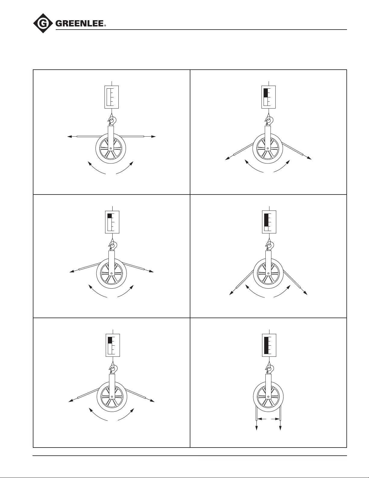
Some Hook Loads Illustrated
Hook Load Hook Load = Total Pulling Force
Hook Sheaves
0
1
2
180°
A straight rope exerts no load on the hook and
structure.
Hook Load = 1/2 of the Pulling Force Hook Load = 1-1/2 Times the Pulling Force
0
1
2
0
1
2
120°
A rope that makes a 120° angle exerts the total
pulling force on the hook and structure.
0
1
2
150°
A rope that makes a 150° angle exerts 1/2 of the
pulling force on the hook and structure.
A rope that makes a 90° angle exerts 1-1/2 times the
pulling force on the hook and structure.
90°
Hook Load = 3/4 of the Pulling Force Hook Load = 2 Times the Pulling Force
0
1
2
135°
A rope that makes a 135° angle exerts 3/4 of the
pulling force on the hook and structure.
Greenlee / A Textron Company
Find Quality Products Online at: [email protected]
www.GlobalTestSupply.com
A rope that makes a 0° angle exerts 2 times the
pulling force on the hook and structure.
5
0
1
2
0°
Page 6
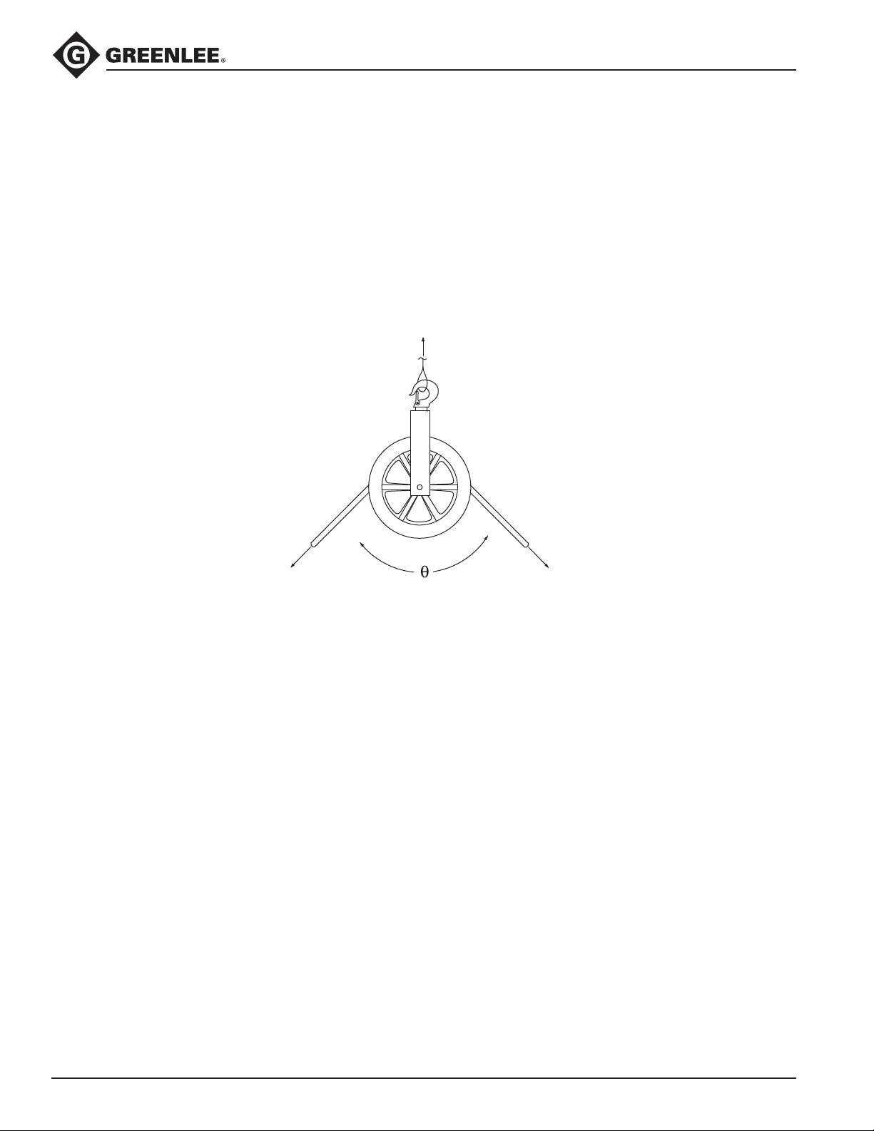
Hook Load (cont’d)
Calculating the Hook Load
One Attachment Point
To calculate the hook load exerted at one attachment
point, use the Reference Table and Formula 1.
Hook Sheaves
R
T
Sheave with One Attachment Point
Formula 1:
R = 2 x T x SIN [(180 – e) / 2]
R = the resultant force, or hook load; this force is exerted on the hook, anchoring and structural support
e = the angle of change in rope direction
T = the tension exerted on the rope by the cable puller
Note: The total load on the support structure = R + the weight of the sheave.
T
Greenlee / A Textron Company
Find Quality Products Online at: [email protected]
www.GlobalTestSupply.com
6
Page 7
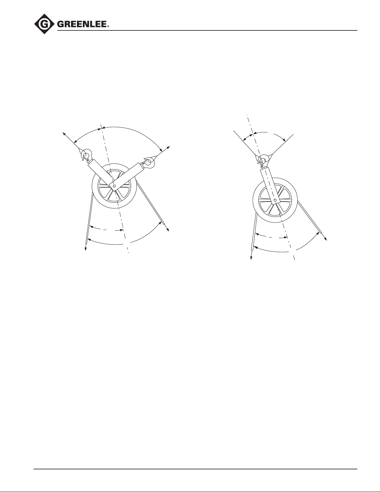
Hook Load (cont’d)
Calculating the Hook Load (cont’d)
Two Attachment Points
To calculate the hook loads exerted at two attachment
points, use the Reference Table and Formulas 1, 2, and 3.
C
L
A
N
G
R1
A
E
L
G
N
A
L
E
B
R2
R1
Hook Sheaves
C
L
E
L
G
N
A
A
N
A
G
L
E
B
R2
1
Q
2
T
Q
T
T
1
Q
2
Q
Sheave with Two Attachment Points
Formula 2: Formula 3:
= ________________________ R2 = ________________________
R
1
RR
COS A + SIN A / TAN B COS B + SIN B / TAN A
R1 = resultant force on left hook, anchoring and support structure
R
= resultant force on right hook, anchoring and support structure
2
A = angle between the left mounting and the centerline of the two legs of the rope
B = angle between the right mounting and the centerline of the two legs of the rope
R = the resultant force, or hook load; this force is exerted on the hook, anchoring and structural support
e = the angle of change in rope direction
T = the tension exerted on the rope by the cable puller
T
Notes: The total load on the left support structure = R
The total load on the right support structure = R2 + the weight of the sheave.
Greenlee / A Textron Company
Find Quality Products Online at: [email protected]
www.GlobalTestSupply.com
+ the weight of the sheave.
1
7
Page 8
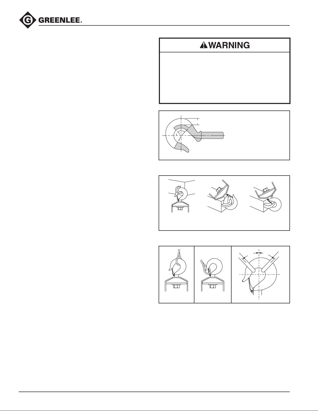
Hoist Hook
Hook Sheaves
Warnings and Application Instructions
• Trained personnel should perform a visual periodic
inspection for deformation, wear, gouges, cracks,
and nicks as part of a documented safety inspection
program in compliance with the ANSI B30.10 schedule. (See ANSI/ASME B30.10 “Hooks” for additional
information.)
• A hook with a gouge, crack, or nick shall be removed
from service and shall be repaired by trained personnel by grinding lengthwise, following the contour of
the hook, provided that the reduced dimension is
within the limits shown in Figure 1. Never use a hook
worn beyond the limits of Figure 1.
• Never use a hook whose tip has been distorted or
bent more than 10 degrees out of plane from the hook
body or whose throat opening has been increased.
(Abent or worn tip will prevent the hook latch from
latching properly.)
• Never rework, reshape, repair, or alter a hook by
welding, bending, heating, or burning.
• Never tip load, side load, or back load a hook. (See
Figure 2.)
• The latch must never support the load, only the hook
may support the load. (See Figure 3.) Regulations
and/or safety codes (OSHA, MSHA, ANSI, ASME,
Insurance, etc.) may require the use of a latch be
mandatory.
• When using two (2) sling legs in a hook, never exceed
45 degrees from the vertical to either sling leg and the
angle between the legs shall not exceed 90 degrees.
• If using more than two (2) slings or for angles greater
than 90 degrees, a bolt type anchor shackle or master
link shall be used to attach the sling legs to the hook.
• Loads may disengage from hook if proper procedures are not followed.
• A falling load may cause serious injury or death.
• Hook must always support the load. The load must
never be supported by the latch.
• Read and understand these instructions before
using hook.
2/3
ZONE A: Repair not required
ZONE B: 10% of original dimension
ZONE C: 5% of original dimension
ZONE D: Do not repair
ZONE B
45° 45°
60°
ZONE A
ZONE C
ZONE D
Figure 1
Side Load Tip Load
Back Load
Wrong
Figure 2
45°45°
Right Wrong
Figure 3 Figure 4 Figure 5
Greenlee / A Textron Company
Find Quality Products Online at: [email protected]
www.GlobalTestSupply.com
8
Page 9
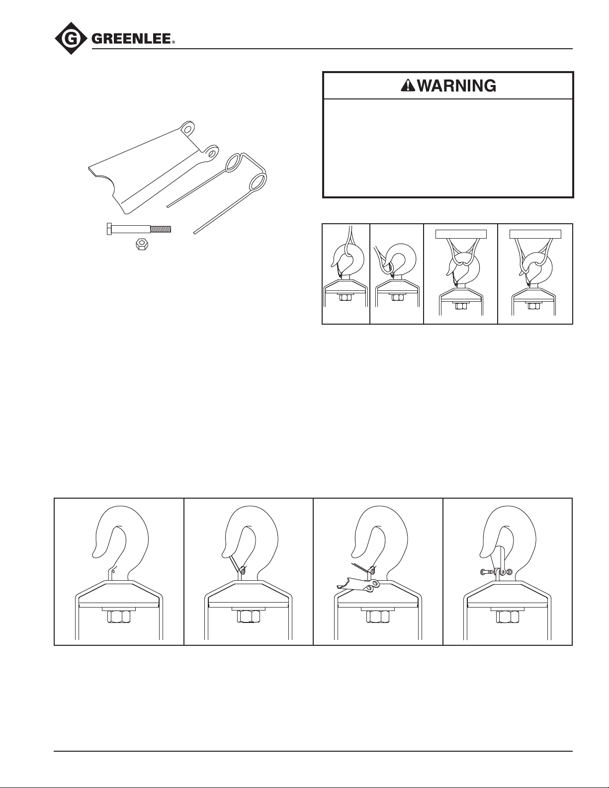
Hook Latch Kit
Hook Sheaves
Warnings and Application Instructions
CAUTION
SEE INSTRUCTIONS
HOOK MUST SUPPORT LOAD
• Always inspect hook and latch before using.
• Never use a latch that is distorted or bent.
• Always make sure spring will force the latch against
the tip of the hook.
• Always make sure hook supports the load. The latch
must never support the load. (See Figures 1 and 2.)
• When placing two (2) sling legs in hook, make sure the
angle between legs is small enough and the legs are
not tilted so that nothing bears against the bottom of
the latch.
(See Figures 3 and 4.)
• Latches are intended to retain loose sling or devices
under slack conditions.
• Latches are not intended to be an anti-fouling device.
•Loads may disengage from hook if proper pro-
cedures are not followed.
• A falling load may cause serious injury or death.
• Hook must always support the load. The load must
never be supported by the latch.
• Read and understand these instructions before
using hook.
SUPPORT SUPPORT
Right Wrong Right Wrong
Figure 1 Figure 2 Figure 3 Figure 4
IMPORTANT — Instructions for Assembling Latch on Hooks
Step 1 Step 2 Step 3 Steps 4, 5, and 6
Place hook at approximately
a 45-degree angle with the
cam up.
Greenlee / A Textron Company
Position coils of spring over
cam with tines of spring
pointing toward point of hook
and loop of spring positioned
down and lying against the
hook.
Position latch over tines of
spring with ears partially over
hook cam. Swing latch to
one side of hook, point and
depress latch and spring until
latch clears point of hook.
9
4. Line up holes in latch with
hook cam.
5. Insert bolt through latch,
spring, and cam.
6. Tighten self-locking nut on
one end of bolt.
Find Quality Products Online at: [email protected]
www.GlobalTestSupply.com
Page 10
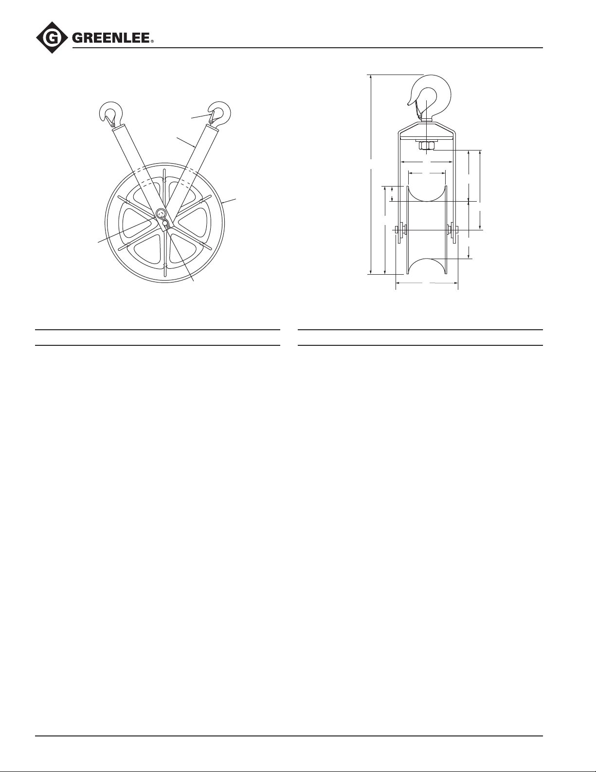
Illustration and Parts List—
639, 650, 651, 652, and 653
2
1
Hook Sheaves
3
6
4,5
Maximum Pulling Force: 17.8 kN (4000 lb) 1/2" – 1-1/4"
Use with Greenlee Easy Tugger
Key Part No. Description Qty Specifications
639
1 50172999 Yoke frame .............................................2
2 90541847 Latch unit, small hook .............................1
3 50153641 Sheave (includes qty. 2 of item 4) ...........1
4 50167987 Bearing ....................................................2
5 50172662 Pin (includes qty. 1 of item 6) .................. 1
6 90503023 Clip, hitch pin, #8 .................................... 2
650
1 50167995 Yoke frame .............................................. 1
2 90526600 Latch unit, small hook .............................1
3 50153625 Sheave (includes qty. 2 of item 4) ...........1
4 50167987 Bearing ....................................................2
5 50251600 Pin (includes qty. 1 of item 6) .................. 1
6 90503023 Clip, hitch pin, #8 .................................... 2
®
and Tugger® Cable Pullers
A ............. 14.9 cm (5.88")
B ............. 92.6 cm (36.46")
C ................ 14 cm (5.50")
D ............. 46.6 cm (18.34")
E ............. 21.7 cm (8.53")
A ............. 17.8 cm (7.00")
B ............. 47.9 cm (18.85")
C ............. 13.8 cm (5.43")
D ............. 24.4 cm (9.62")
E ............. 20.6 cm (8.10")
B
J
H
C
F
A
F ............. 11.4 cm (4.50")
G ................ 50 cm (19.62")
H ................ 61 cm (24.00")
J ................ 5.6 cm (2.19")
M/Wt. ........ 20.4 kg (45.0 lb)
F ............. 11.4 cm (4.50")
G ............... 7.6 cm (3.00")
H ............. 15.2 cm (6.00")
J ................ 3.8 cm (1.50")
M/Wt. ........ 5.08 kg (11.2 lb)
E
D
G
651
1 50168002 Yoke frame .............................................. 1
2 90541847 Latch unit, small hook .............................1
3 50153587 Sheave (includes qty. 2 of item 4) ...........1
4 50167987 Bearing ....................................................2
5 50167979 Pin (includes qty. 1 of item 6) .................. 1
6 90503023 Clip, hitch pin, #8 .................................... 2
A ............. 17.8 cm (7.00")
B ............. 53.1 cm (20.89")
C ............. 14.6 cm (5.75")
D ............. 23.8 cm (9.37")
E ............. 15.4 cm (6.06")
F ............. 11.4 cm (4.50")
G ............. 16.8 cm (6.62")
H ................ 27 cm (10.62")
J ................ 5.1 cm (2.00")
M/Wt. .......... 7.7 kg (17.0 lb)
652
1 50168010 Yoke frame .............................................. 1
2 90526600 Latch unit, small hook .............................1
3 50153633 Sheave (includes qty. 2 of item 4) ...........1
4 50167987 Bearing ....................................................2
5 50251600 Pin (includes qty. 1 of item 6) .................. 1
6 90503023 Clip, hitch pin, #8 .................................... 2
A ............. 17.8 cm (7.00")
B ............. 79.6 cm (31.35")
C ............. 13.8 cm (5.43")
D ............. 41.0 cm (16.13")
E ............. 23.2 cm (9.13")
F ............. 11.4 cm (4.50")
G ............. 35.6 cm (14.00")
H ............. 45.7 cm (18.00")
J ................ 5.1 cm (2.00")
M/Wt. ...... 13.52 kg (29.8 lb)
653
............. 11.4 cm (4.50")
1 50168029 Yoke frame .............................................. 1
2 90541847 Latch unit, small hook .............................1
3 50153641 Sheave (includes qty. 2 of item 4) ...........1
4 50167987 Bearing ....................................................2
5 50167979 Pin (includes qty. 1 of item 6) .................. 1
6 90503023 Clip, hitch pin, #8 .................................... 2
Greenlee / A Textron Company
Find Quality Products Online at: [email protected]
www.GlobalTestSupply.com
A ............. 17.8 cm (7.00")
B ............. 86.6 cm (34.08")
C ............. 14.6 cm (5.75")
D ............. 40.3 cm (15.87")
E ............. 15.4 cm (6.06")
10
F
G ............. 49.8 cm (19.62")
H ................ 61 cm (24.00")
J .............. 5.72 cm (2.25")
M/Wt. ........ 15.9 kg (35.0 lb)
Page 11
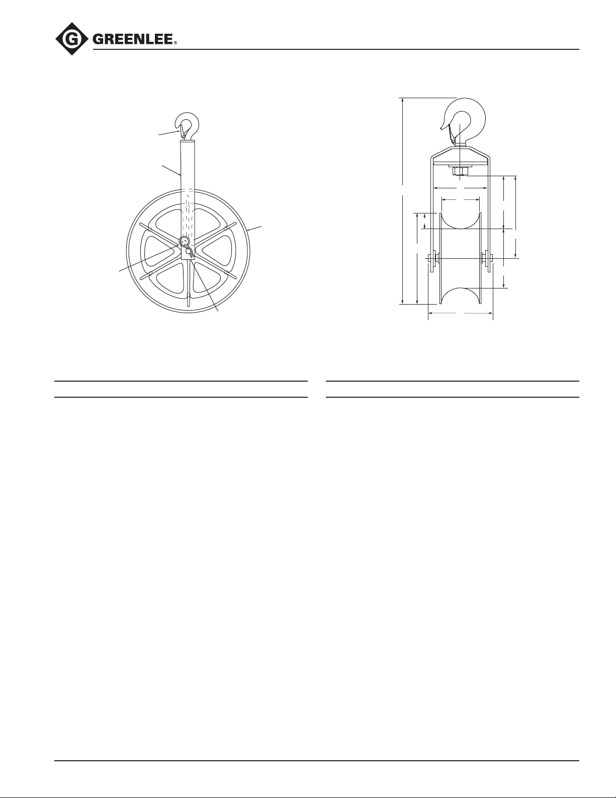
Illustration and Parts List—8012, 8018, and 8024
2
1
Hook Sheaves
3
6
4,5
Maximum Pulling Force: 35.6 kN (8000 lb)
Use with Greenlee Easy Tugger
Key Part No. Description Qty Specifications
8012
1 50008544 Yoke frame .............................................. 1
2 90541855 Latch unit, large hook ..............................1
3 50008439 Sheave (includes qty. 2 of item 4) ...........1
4 90548388 Bearing ....................................................2
5 50008382 Pin, sheave ..............................................1
6 90503023 Clip, hitch pin, #8 .................................... 2
®
, Tugger®, Super Tugger®, and Ultra Tugger® Cable Pullers
A ............. 20.0 cm (7.87")
B ............. 59.3 cm (23.35")
C ............. 15.2 cm (6.00")
D ............. 22.9 cm (9.00")
E ................ 13 cm (5.125")
B
J
H
C
F
A
F ............. 11.4 cm (4.5")
G ............. 19.7 cm (7.75")
H ............. 29.8 cm (11.75")
J ................ 5.1 cm (2.00")
M/Wt. ........ 12.4 kg (27.4 lb)
E
D
G
8018
1 50008552 Yoke frame .............................................. 1
2 50296019 Latch unit, large hook ..............................1
3 50008447 Sheave (includes qty. 2 of item 4) ...........1
4 90548388 Bearing ....................................................2
5 50008463 Pin, sheave ..............................................1
6 90503023 Clip, hitch pin, #8 .................................... 2
8024
1 50008560 Yoke frame .............................................. 1
2 50296019 Latch unit, large hook ..............................1
3 50008455 Sheave (includes qty. 2 of item 4) ...........1
4 90548388 Bearing ....................................................2
5 50008501 Pin, sheave ..............................................1
6 90503023 Clip, hitch pin, #8 .................................... 2
Greenlee / A Textron Company
A ............. 22.6 cm (8.90")
B ............. 77.4 cm (30.47")
C ............. 18.5 cm (7.28")
D ............. 40.7 cm (16.03")
E ............. 22.9 cm (9.03")
A ............. 23.8 cm (9.38")
B ........... 92.20 cm (36.30")
C ............. 18.5 cm (7.28")
D ............. 40.6 cm (15.98")
E ........... 15.52 cm (6.11")
11
F ................ 14 cm (5.50")
G ............. 35.6 cm (14.00")
H ............. 45.7 cm (18.00")
J ................ 5.1 cm (2.00")
M/Wt. ........ 19.3 kg (42.6 lb)
F ............. 15.2 cm (6.00")
G ............. 50.2 cm (19.75")
H ................ 61 cm (24.00")
J ................ 5.4 cm (2.125")
M/Wt. ........ 28.5 kg (62.9 lb)
Find Quality Products Online at: [email protected]
www.GlobalTestSupply.com
 Loading...