

Page 1
INSTRUCTION MANUAL
INSTRUCTION MANUAL
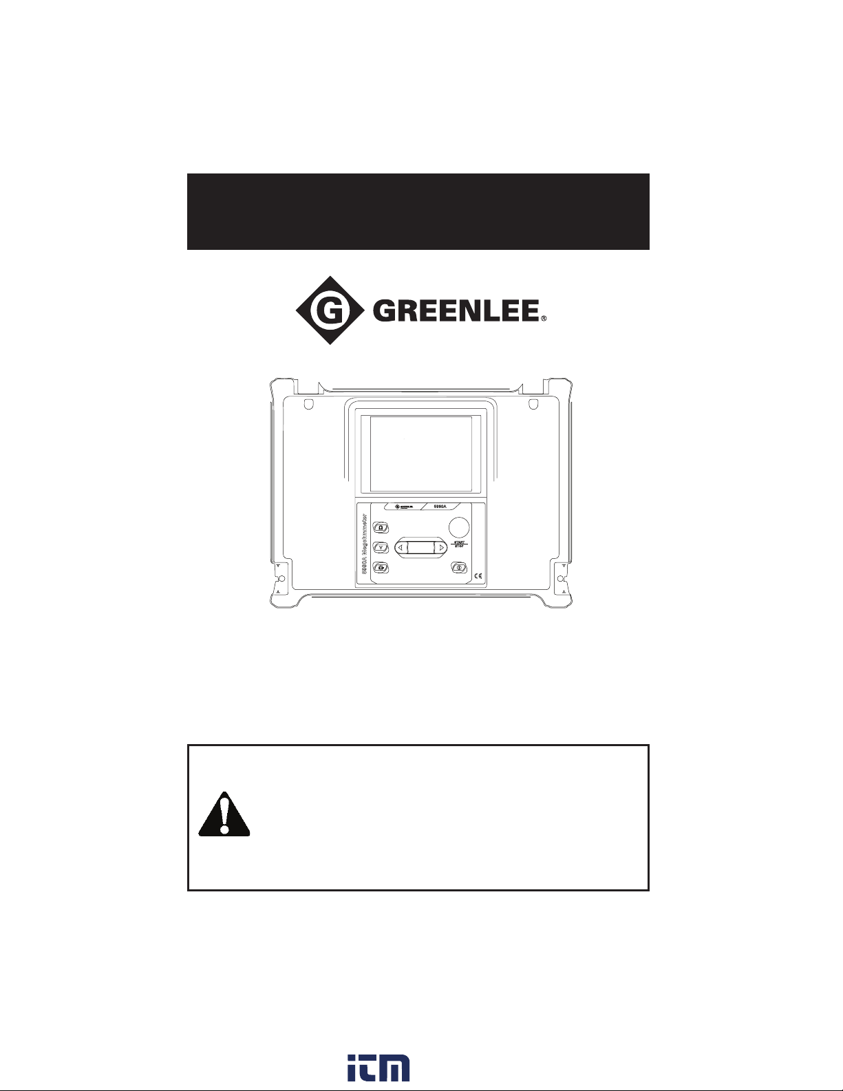
5990A
Megohmmeter
Read and understand all of the instructions and safety information in this
manual before operating or servicing this tool.
52084986 © 2018 Greenlee Tools, Inc. 8/18
www. .com
[email protected]1.800.561.8187
Page 2

Table of Contents
Description .............................................................................................. 3
Safety
...................................................................................................... 3
Purpose.................................................................................................... 3
Important Safety Information............................................................... 4–6
Identification
LC Display
Operator’s Panel
Connectors
High Voltage Shielded Test Tips with High Voltage Alligator Clips
Performing Measurements
Measurements
General Information About DC High Voltage Testing
Guard Terminal
Insulation Resistance Measurement
Voltage Measurement
Maintenance
Specifications
Accuracy
Measurements
Insulation Resistance
General Capability vs Resistance
Voltage
General Specifications
Measurement Categories
Statement of Conformity
.......................................................................................7-11
......................................................................................... 7
................................................................................ 8
.................................................................................. 9–10
... 11
.............................................................. 12–13
................................................................................. 14–18
........................ 14
................................................................................ 15
......................................... 16–17
..................................................................... 18
.................................................................................... 19–21
................................................................................. 22–23
......................................................................................... 22
................................................................................ 22
...................................................................... 22
.................................................... 23
............................................................................................ 23
........................................................................... 24
...................................................................... 25
....................................................................... 25
2
www. .com
[email protected]1.800.561.8187
Page 3
5990A
Description
The Greenlee 5990A Megohmmeter is intended to test insulation and detect voltage. The unit
features an easy-to-read and accurate analog scale.
Safety
Safety is essential in the use and maintenance of Greenlee tools and equipment. This instruction manual and any markings on the tool provide information for avoiding hazards and unsafe
practices related to the use of this tool. Observe all of the safety information provided.
Purpose
This instruction manual is intended to familiarize all personnel with the safe operation and
maintenance procedures for Greenlee 5990A Megohmmeter.
Keep this manual available to all personnel.
Replacement manuals are available upon request at no charge.
Greenlee and are registered trademarks of Greenlee Tools, Inc.
Do not discard this product or throw away!
All specifications are nominal and may change as design improvements occur. Greenlee Tools, Inc. shall not be liable for
damages resulting from misapplication or misuse of its products.
® Registered: The color green for electrical test instruments is a registered trademark of Greenlee Tools, Inc.
KEEP THIS MANUAL
www. .com
[email protected]1.800.561.8187
3
Page 4
Important Safety Information
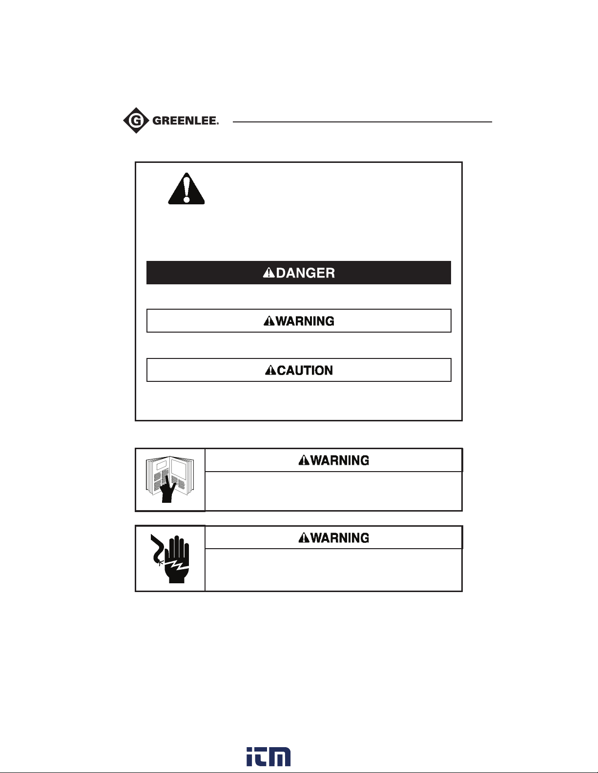
SAFETY ALERT SYMBOL
This symbol is used to call your attention to hazards or unsafe practices which could
result in an injury or property damage. The signal word, defined below, indicates the
severity of the hazard. The message after the signal word provides information for
preventing or avoiding the hazard.
Immediate hazards which, if not avoided, WILL result in severe injury or death.
Hazards which, if not avoided, COULD result in severe injury or death.
Hazards or unsafe practices which, if not avoided, MAY result in injury or
property damage.
Read and understand this material before operating or servicing this
equipment. Failure to understand how to safely operate this tool can
result in an accident causing serious injury or death.
Electric shock hazard:
Contact with live circuits can result in severe injury or death.
4
www. .com
[email protected]1.800.561.8187
Page 5
5990A
Important Safety Information
Electric shock and fire hazard:
• Do not expose this unit to rain or moisture.
• Do not use the unit if it is wet or damaged.
• Use test leads or accessories that are appropriate for the application. See the category and
voltage rating of the test lead or accessory.
• Inspect the test leads before use. They must be clean and dry, and the insulation must be in
good condition.
• Use this unit for the manufacturer’s intended purpose only, as described in this manual.
Anyotheruse can impair the protection provided by the unit.
Failure to observe these warnings could result in severe injury or death.
Electric shock hazard:
• Do not apply more than the rated voltage between any two input terminals, or between any
input terminal and earth ground.
• Do not contact the test lead tips or any uninsulated portion of the accessory.
• Do not contact the test lead tips while performing the insulation resistance test.
Failure to observe these warnings could result in severe injury or death.
Electric shock hazard:
• Do not operate with the case open.
• Before opening the case, remove the test leads from the circuit and shut off the unit.
Failure to observe these warnings could result in severe injury or death.
Electric shock hazard:
• Unless measuring voltage, shut off and lock out power. Make sure that all capacitors are
discharged. Voltage must not be present.
• Using this unit near equipment that generates electromagnetic interference can result in
unstable or inaccurate readings.
Failure to observe these warnings could result in severe injury or death.
www. .com
[email protected]1.800.561.8187
5
Page 6
Important Safety Information
Electric shock hazard:
• Do not attempt to repair this unit. It contains no user-serviceable parts.
• Do not expose the unit to extremes in temperature or high humidity. See Specifications.
Failure to observe these precautions may result in injury and can damage the unit.
Working with the instrument:
• Equipment under test must be switched off (i.e. de-energized) before test leads are con-
nected to the equipment.
• Do not touch any conductive parts of equipment under test during the test.
• Make sure that the tested object is disconnected (mains voltage disconnected) before start-
ing the Insulation Resistance measurement!
• Do not touch the tested object whilst testing it, risk of electric shock!
• In case of a capacitive test object (long tested cable etc.), automatic discharge of the object
may not be done immediately after finishing the measurement – “Please wait, discharging”
message will be displayed.
Handling with capacitive loads:
• Note that 40 nF charged to 1 kV or 9 nF charged to 5 kV are hazardous live!
• Never touch the measured object during the testing until it is totally discharged.
• Maximum external voltage between any two leads is 600 V (CAT IV environment).
Electric shock hazard:
Contact with live circuits can result in severe injury or death.
6
www. .com
[email protected]1.800.561.8187
Page 7
5990A
Instrument Description
Instrument Casing
The instrument is housed in a plastic box that maintains the protection class defined in the
general specifications.
LCD
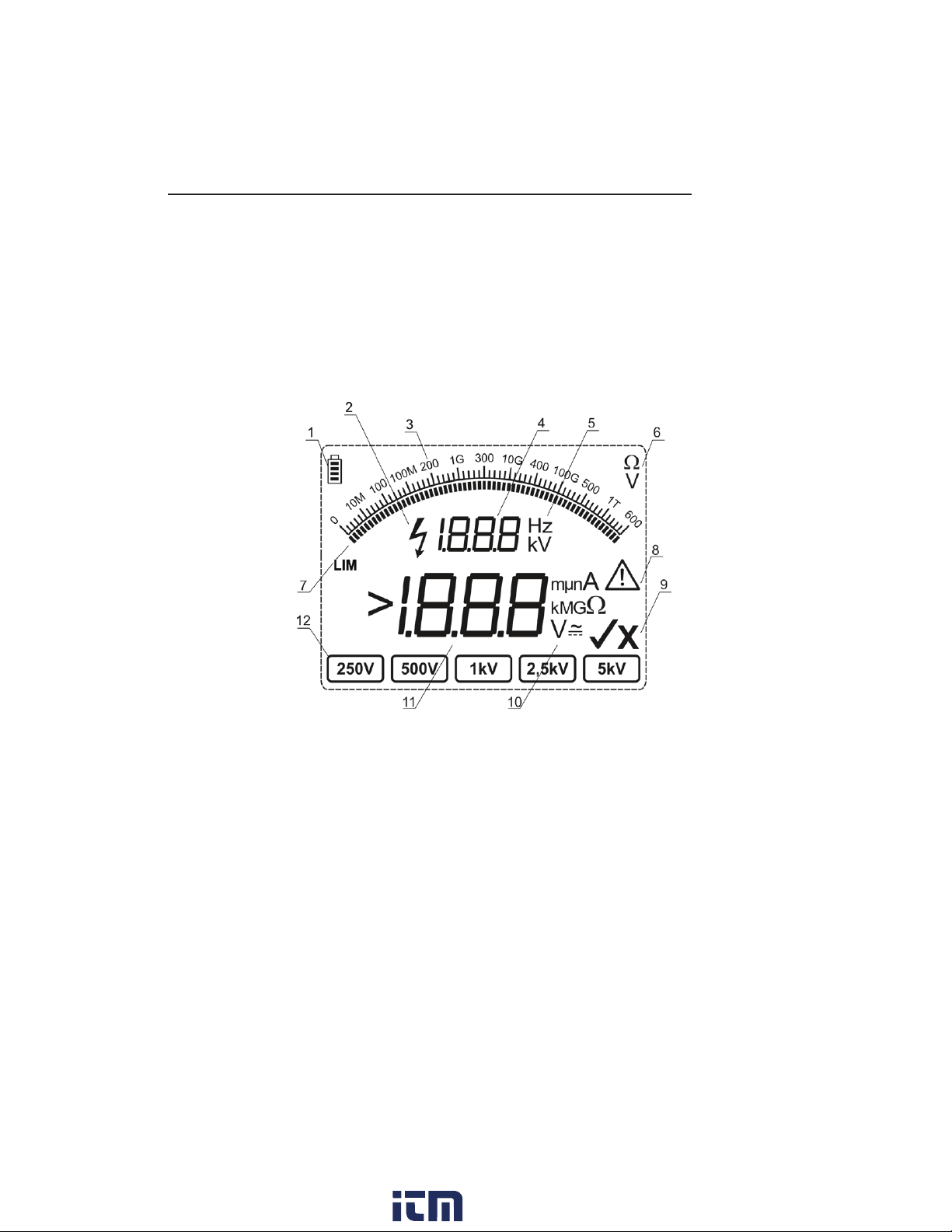
The LCD has a backlight and offers easy-to-read results. See Fig.1 below.
Fig. 1 LCD Display
Legend:
1.......... Battery indicator: This indicates condition of the battery. In battery charging mode it flashes.
2.......... Hazardous Voltage Warning icon: This indicates that voltage higher than 70 V may be
present at the test terminals!
3.......... Analog display
4.......... Auxiliary digital display
5.......... Auxiliary units
6.......... Analog units
7.......... Bar graph
8.......... Warning icon: Carefully read and understand the User Manual.
9.......... Pass or Fail icon
10........ Main units
11........ Main digital display
12........ Test voltage: Menu for selecting the test voltage.
7
www. .com
[email protected]1.800.561.8187
Page 8
5990A Megohmmeter
Instrument Description (cont’d)
Operator’s Panel
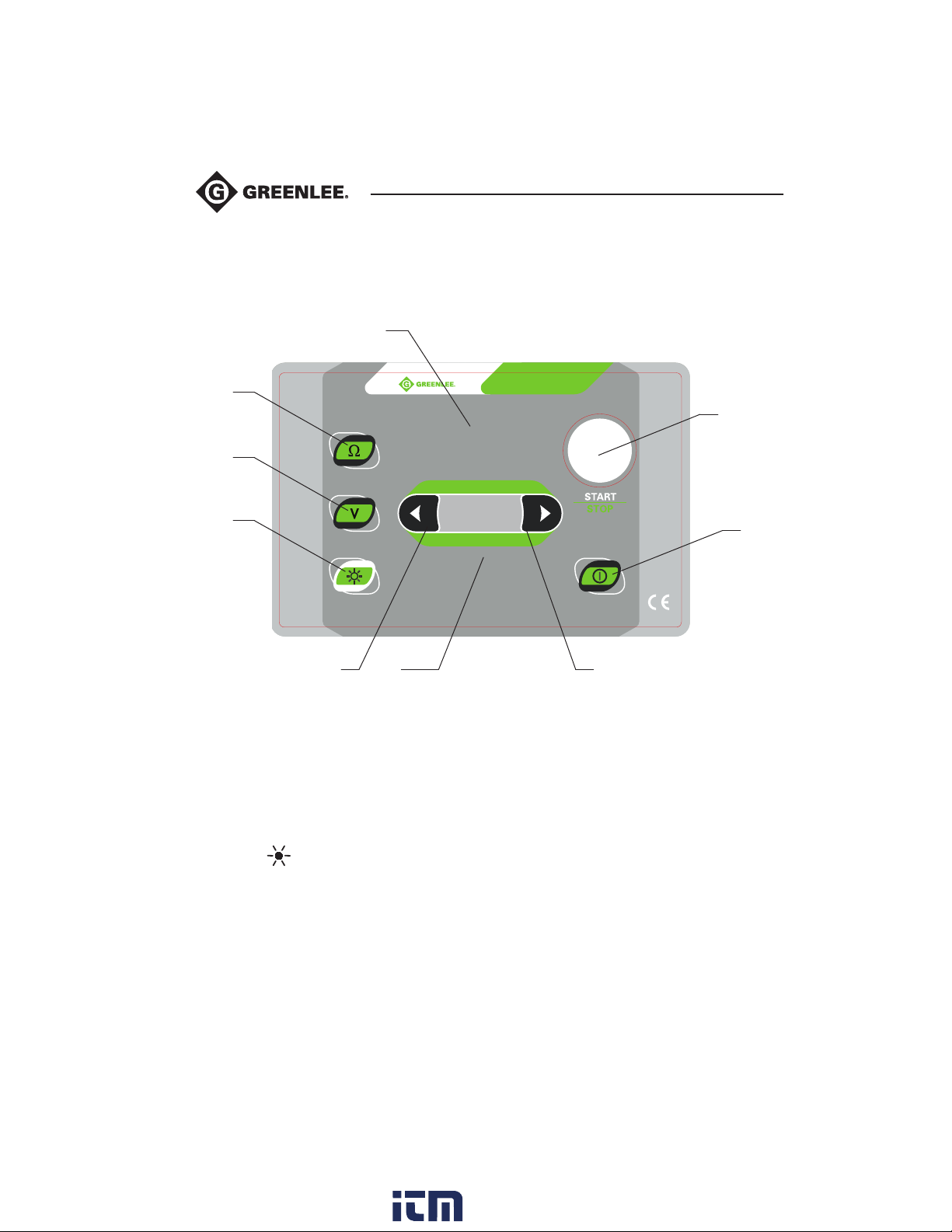
The operator’s panel is shown in Fig. 2 below.
LCD
1
2
3
Keypad4 5
Fig. 2. Front Panel
5990A
52085064 REV1
Legend:
1...........Ω: Press to switch to Insulation Measurement Mode. Press again to set a resistance
limit value.
2.......... V: Press to switch to Voltage measurement mode.
3.......... Light: Press to to turn the display backlight ON or OFF.
4.......... t cursor: Press to decrease the test voltage parameter or resistance limit value.
5.......... u cursor: Press to increase the test voltage parameter or resistance limit value.
6.......... START/STOP: Press to start or stop insulation measurement.
7.......... ON/OFF: Press to switch the instrument ON or OFF.
6
7
8
www. .com
[email protected]1.800.561.8187
Page 9
5990A
Instrument Description (cont’d)
Connectors
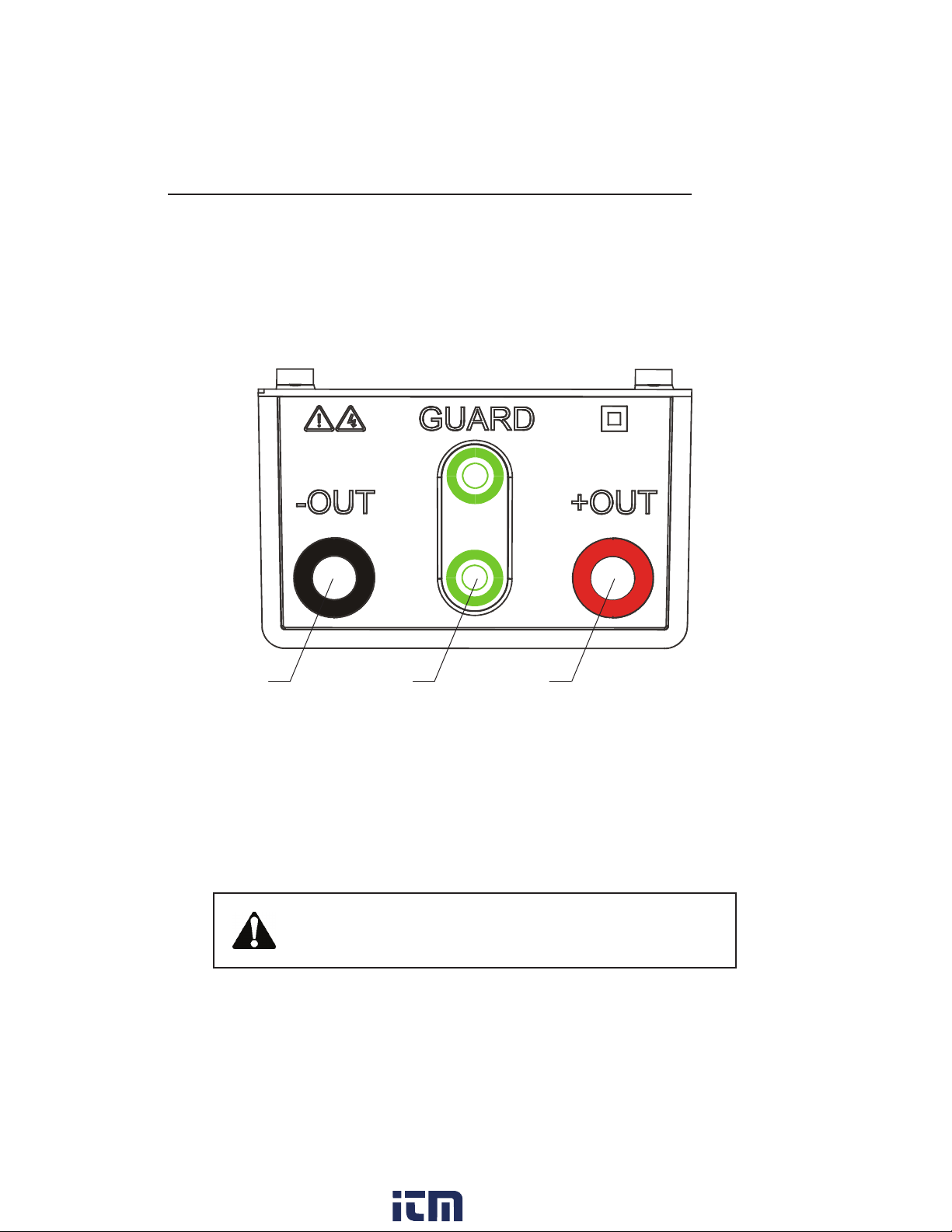
The 5990A Tester contains the following connections:
• Four banana safety sockets for test leads (Fig. 3).
• Socket for mains supply cable (Fig. 4).
1 2 3
Fig. 3 Test Leads Connector Diagram
1.......... (-OUT): Negative Insulation Resistance test terminal
2.......... GUARD: Guard terminals are intended to lead away potential leakage current while
measuring the Insulation. Both green sockets are connected together inside of
the instrument.
3.......... (+OUT): Positive Insulation Resistance test terminal
Use original test accessories only!
Max allowed external voltage between test terminals and ground is 600V!
Max allowed external voltage between test terminals is 600V!
9
www. .com
[email protected]1.800.561.8187
Page 10
Instrument Description (cont’d)
Connectors (cont’d)
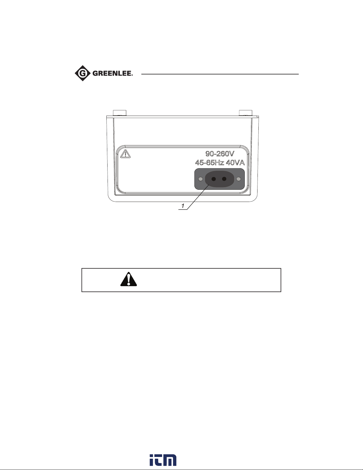
Fig. 4 Mains Connector
1..........Mains connector: This is to connect the instrument to the mains supply.
Use original mains supply cable only!
10
www. .com
[email protected]1.800.561.8187
Page 11
5990A
Instrument Description (cont’d)
High Voltage Shielded Test Tips with High Voltage Alligators Clips
Fig.5
Fig.6
Application notes:
These test leads are designed for diagnostic testing of
insulation and hand held testing of insulation.
Insulation ratings:
• High voltage banana connector (red, black): 5kV d.c
(double insulation). See Fig.5.
• High voltage tip (red, black): 5kV d.c
(double insulation).
• Alligator (red, black): 5kV d.c (double insulation).
See Fig.6.
• Guard banana connector (green): 600V CAT IV
(double insulation).
• Cable (yellow): 12kV (shielded). See Fig.5.
Guard Test Lead with Alligator
Insulation ratings:
• Guard test lead with banana connectors (green): 600V CAT IV (double insulation);
• Alligator (green): 600V CAT IV (double insulation).
www. .com
11
[email protected]1.800.561.8187
Page 12
Performing Measurements
Switching On the Instrument
Auto-Calibration
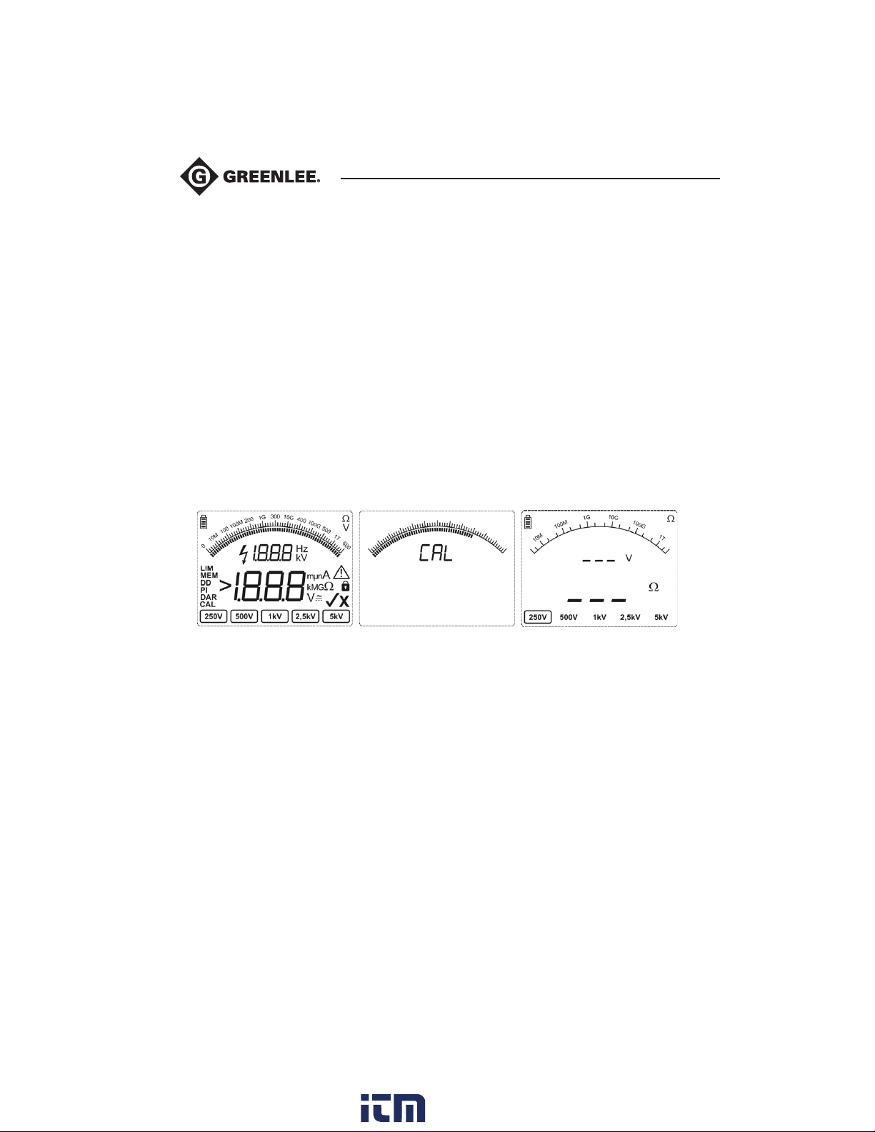
The instrument is switched ON by pressing the ON/OFF key. After turning on (Fig. 7), the
instrument executes the auto-calibration (Fig. 8).
Note: If batteries are defective or missing and the instrument is powered from mains supply, the
instrument cannot be turned ON.
The test leads have to be disconnected during auto-calibration. If not, the auto-calibration
procedure could fail. After finishing the auto-calibration, the pass icon will appear; the
instrument will go into Insulation Mode (Fig.9) and be ready for normal operation.
Auto-calibration ensures accuracy when measuring very low currents. It compensates for the
effects caused by aging, temperature and humidity changes. Performing a new auto-calibration
is recommended when the temperature changes by more than 10° F (5°C).
Fig. 7 Initial State Fig. 8 Auto-Calibration State Fig. 9 Insulation Measuring Mode
12
www. .com
[email protected]1.800.561.8187
Page 13

5990A
Performing Measurements (cont’d)
Note: If the instrument detects a faulty state during the auto-calibration, the fail icon (X) will
be displayed:
A common reason for failure is improper environmental conditions. This includes excessive hu-
midity or excessive temperature. In this case it is possible to perform measurements by pressing
the START/STOP button again but results could be outside of the technical specification.
Mains powered instrument operation
Connecting the instrument to the mains supply while the instrument is OFF will charge the batteries. The instrument will remain OFF during this period. If the batteries are charging, a flashing
battery indicator will appear in the upper left corner of the LCD.
Note: If batteries are defective or missing, the charger will not work.
Connecting the instrument to the mains supply while the instrument is ON will cause the instrument to be powered by the mains supply. If the instrument is not in Insulation Measuring Mode*,
the internal charger will charge the batteries. If the batteries are charging, a flashing battery
indicator will appear in the upper left corner of the LCD.
Note: It is not recommended to connect or disconnect the instrument to mains supply while the
instrument is in Insulation Measuring Mode*.
*Insulation Measuring Mode: When the instrument performing insulation measurements.
Backlight operation (battery powered instrument)
After turning the instrument ON, the LCD backlight is automatically turned ON. It can be turned
OFF and ON by pushing the button.
Backlight operation (mains powered instrument)
After turning the instrument ON, the LCD backlight is automatically turned OFF. It can be turned
OFF and ON by pushing the button.
Off function
The instrument can be switched OFF by pressing the ON/OFF button.
www. .com
13
[email protected]1.800.561.8187
Page 14
Measurements
Itest
Guar
General Information about DC High voltage testing
The purpose of insulation tests
Insulating materials are important parts of almost every electrical product. The material’s properties depend not only on its compound characteristics but also on temperature, pollution, moisture, aging, electrical and mechanical stress, etc. Safety and operational reliability require the
regular maintenance and testing of the insulation material to ensure it is kept in good operational
condition. High voltage tests are used to test insulating materials.
DC vs. AC testing voltage
Testing with a DC voltage is widely accepted as being as useful as testing with AC and / or
pulsed voltages. DC voltages can be used for breakdown tests especially where high capacitive
leakage currents interfere with measurements using AC or pulsed voltages. DC is mostly used
for insulation resistance measurement tests. In this type of test, the voltage is defined by the
appropriate product application group. This test voltage is lower than the voltage used in the
withstanding voltage test so the tests can be applied more frequently without stressing the test
material.
Electrical representation of insulating material
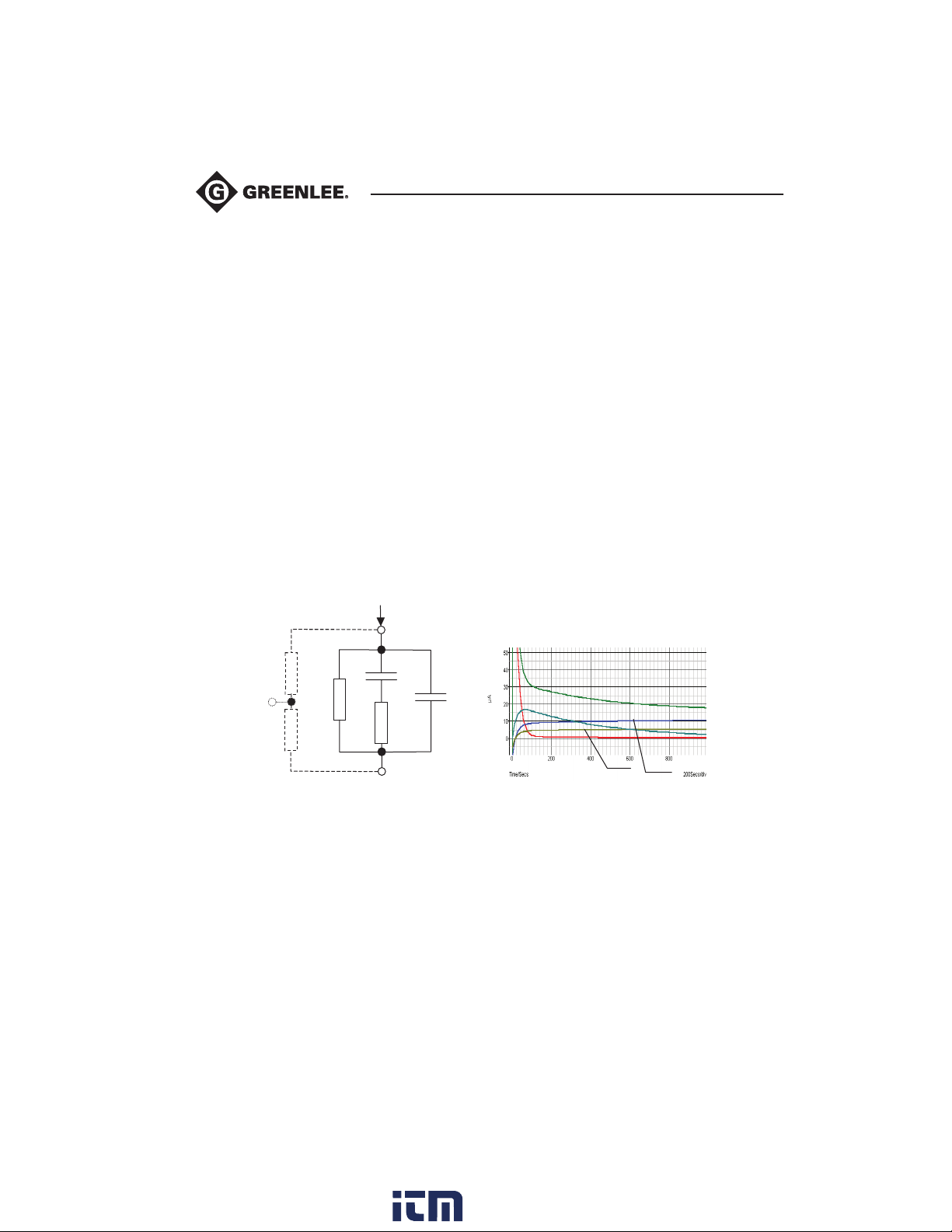
The following figure (Fig.10) represents the equivalent electrical circuit of insulating material
surface
Riss1
d
Riss2
R
and R
iss1
R
– the actual insulation resistance of material
iso
C
– capacitance of material
iso
C
, Rpi - represents polarization effects.
pi
- the surface resistivity (position of optional guard connection)
iss2
Riso
+
Rpi
-
material
Cpi
Ciso
Fig. 10
The right figure shows typical currents for that circuit.
I
= overall test current (I
test
I
= polarization absorption current
PI
I
= actual insulation current
RISO
I
= surface leakage current
RISS
14
test
= IPI+ I
RISO
+ I
RISS
)
Itest
I
PI
I
Ci so
I
Ri soIRi ss
www. .com
[email protected]1.800.561.8187
Page 15
5990A
Measurements (cont’d)
I
A
A
D
Guard terminal
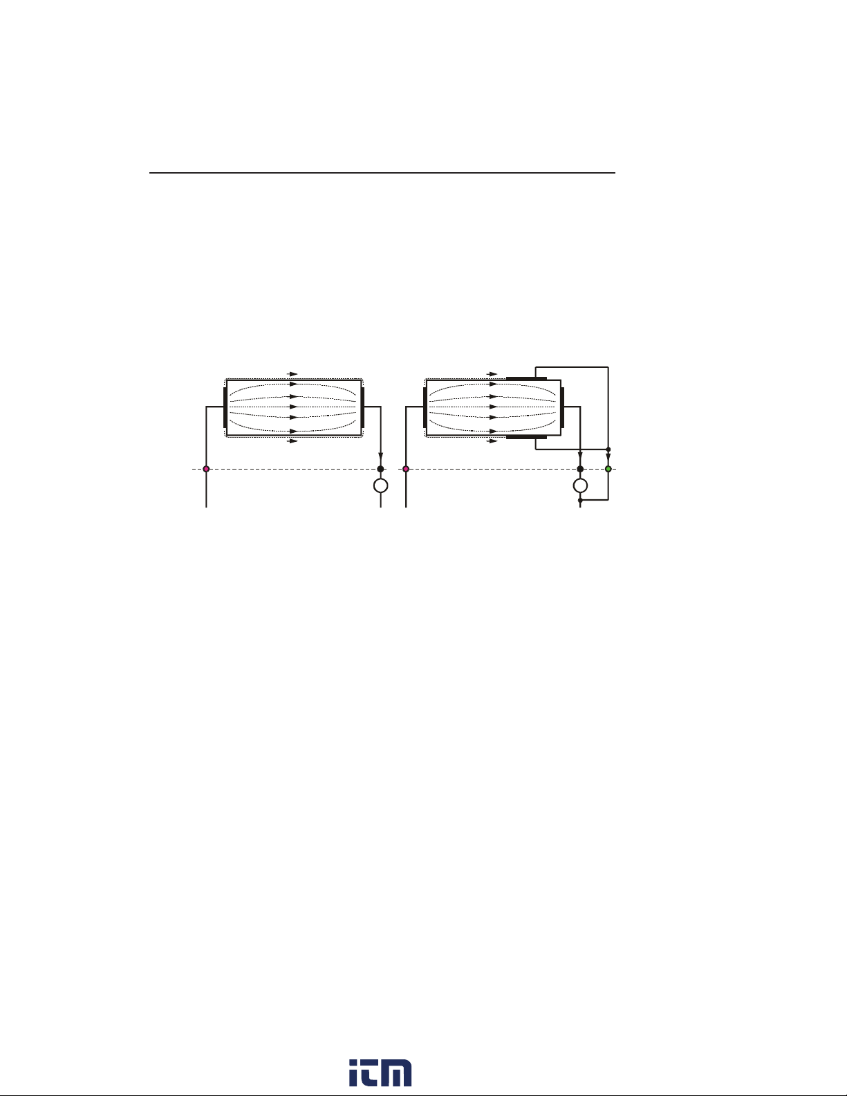
The purpose of the GUARD terminal is to lead away potential leakage currents (e.g. surface
currents), which are not a result of the measured insulation material itself but are a result of
surface contamination and moisture. This current interferes with the Insulation Resistance
Measurement. The GUARD terminal is internally connected the negative test terminal (black). The
GUARDs test clip should be connected to the test object so that most of the unwanted leakage
current is collected. See Fig. 11 below.
L
I
M
I
L
I
+OUT +OUT
U
t
Fig. 11 Connection of GUARD Terminal to Measured Object
-OUT
A
Where:
Ut........Test voltage
I
.........Leakage current (resulted by surface dirt and moisture)
L
I
........Material current (resulted by material conditions)
M
I
.........A-meter current
A
Result without using GUARD terminal: RINS = U
/ IA = Ut / (IM + IL) …incorrect result.
t
U
I
M
I
A
I
-OUT GUAR
t
L
Result using GUARD terminal: RINS = Ut / IA = Ut / IM ……correct result.
It is recommended to use the GUARD connection when high insulation resistance (>10G Ω)
is measured.
Note:
• The guard terminal is protected by an internal impedance (200 KΩ).
The instrument has two guard terminals to allow easy connection of shielded measuring leads.
15
www. .com
[email protected]1.800.561.8187
Page 16
Measurements (cont’d)
Initial display
Display with results
Insulation Resistance measurement
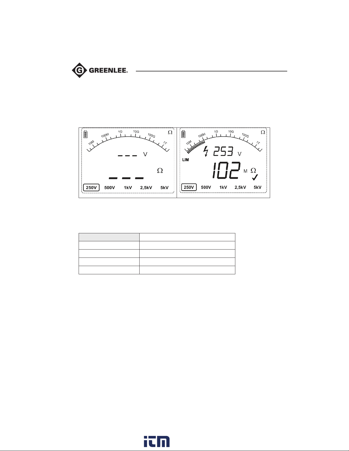
Select this function by pressing the Ω button. It will display the following states (Initial Display
and Display with results). See Fig. 12 below.
Fig. 12 Insulation Resistance Function Display States
Legend of displayed symbols in Fig 12:
Insulation Resistance Name of selected function
250V Selected test voltage
253 V Actual test voltage (measured value)
102 MΩ Insulation Resistance – result
Bar Analog presentation of result
Measurement procedure:
• Connect the test leads to the instrument and to the test object.
• Select INSULATION RESISTANCE mode by pressing the Ω button.
• Press the START/STOP button and release it. This will begin continuous measurement.
• Wait until the test result has stabilized then press the START/STOP button again to stop
the measurement.
• Wait to remove the object under test until it is discharged.
Notes:
• A high-voltage warning symbol appears on the display during the measurement to warn the
operator of a potentially dangerous test voltage.
16
www. .com
[email protected]1.800.561.8187
Page 17
5990A
Measurements (cont’d)
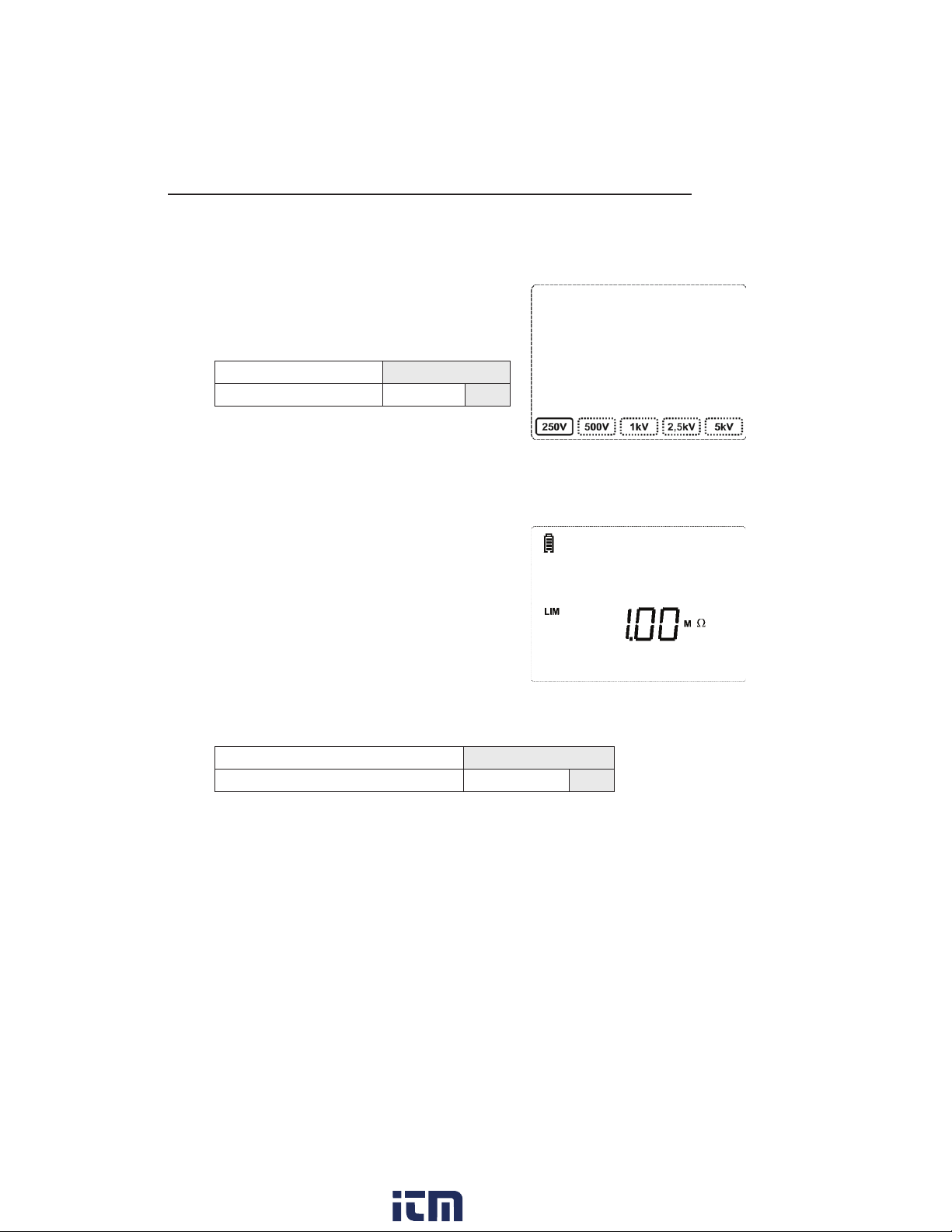
Set-up test voltage for Insulation Resistance (Fig.13):
Adjust test voltage using the t and u buttons.
Legend of displayed symbols:
Name of selected function Insulation Resistance
Selected test voltage Nominal 250V
Set-Up Insulation Resistance Limit Value for
Insulation Resistance (Fig.13):
• Press the Ω button
• Adjust the limit value using the t and u buttons
• Press the Ω button again or the START button to
return to the insulation resistance measurement menu.
Fig. 13 Set-Up Test Voltage in Insulation
Resistance Measurement
Fig. 13a Set-Up Insulation
Resistance Limit Value
Legend of displayed symbols:
Name of selected function Insulation Resistance
Selected Insulation Resistance Limit Value Resistance Value 1 MΩ
Insulation resistance limit selection range: [10 kΩ .. 2--MΩ]
No limit selected indication: – – –
Warning!
Refer to Warnings chapter for safety precautions!
17
www. .com
[email protected]1.800.561.8187
Page 18
Measurements (cont’d)
Voltage Measurement
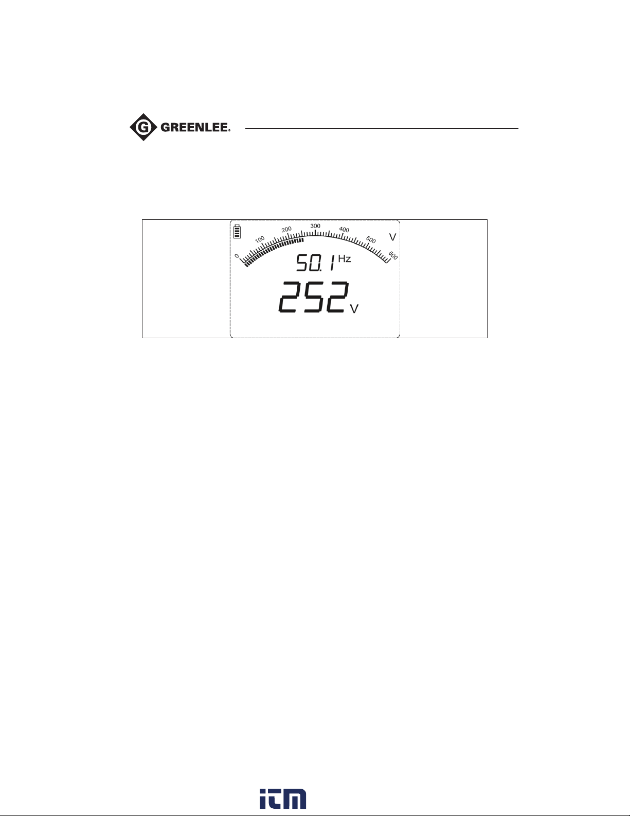
Select this function by pressing the V button. Voltage measurement is active immediately after
entering the function. See Fig. 14 below.
Fig. 14 Voltage Function Display
Measurement Procedure:
• Connect the test leads to the instrument and to the measured source.
• Press the V button to select voltage mode and continuous measurement will automatically
start to run.
Warning!
Refer to Warnings chapter for safety precautions!
18
www. .com
[email protected]1.800.561.8187
Page 19
5990A
Maintenance
Electric shock hazard:
• Do not attempt to repair this unit. It contains no user-serviceable parts.
• Do not expose the unit to extremes in temperature or high humidity. See Specifications.
Failure to observe these precautions may result in injury and can damage the unit.
Electric shock hazard:
Before opening the case, remove the test leads from the circuit and shut off the unit.
Inspection
To maintain the operator’s safety and to ensure the reliability of the instrument it is advisable to
inspect the instrument on a regular basis. Check that the instrument and its accessories are not
damaged. If any defect is found please consult the Greenlee Service Center at 800-435-0786.
Insertion and Charging Batteries for the First Time
Battery cells are stored in the bottom section of the instrument casing under the battery cover
(see Fig. 15). When inserting batteries for the first time please note the following:
• Disconnect any measurement accessories or mains supply cable connected to the instrument
before opening the battery cover to avoid electric shock.
• Remove the battery cover.
• Insert batteries correctly (see Fig. 15), otherwise the test instrument will not operate!
• Replace the battery cover and fixed the cover back in place.
Connect the instrument to the mains power supply for 14 hours to fully charge batteries.
(Typical charging current is 300 mA).
When you charge the batteries for the first time, it normally takes about 3 charge and discharge
cycles for the batteries to regain their full capacity.
Replacement and Charging of Batteries
The instrument is designed to be powered by rechargeable batteries supported by mains
supply. The LCD contains an indication of battery condition (upper left section of LCD). When the
low-battery indication appears (Err), the batteries have to be recharged. Connect the instrument
to the mains power supply for 14 hours to recharge cells. Typical charging current is 300 mA.
Note:
• Operator does not need to disconnect the instrument from mains supply after the full
recharging period. The instrument can be connected permanently.
Fully charged rechargeable batteries can supply the instrument for approx. 4 hours.
(Continues testing at 5kV)
19
www. .com
[email protected]1.800.561.8187
Page 20
Maintenance (cont’d)
If the batteries have been stored for a long time, it normally takes about 3 charge and discharge
cycles for the batteries to regain full capacity.
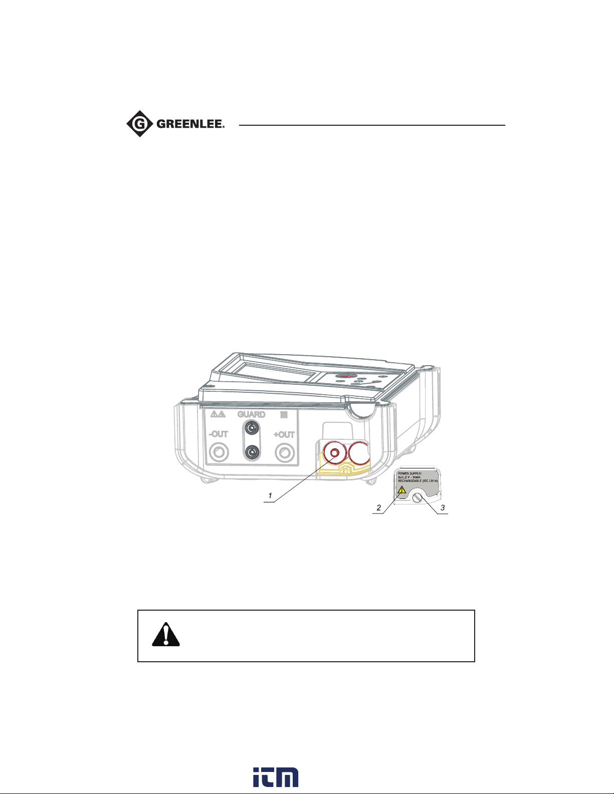
Battery cells are stored in the bottom section of the instrument under the battery cover
(see Fig. 15). In case of defective batteries please note the following:
• Turn the power off and disconnect any measurement accessories and the mains supply cable
before opening the battery cover to avoid electric shock.
• Remove the battery cover.
• All six cells have to be replaced.
• Insert the batteries correctly (see Fig. 15), otherwise the test instrument will not operate and
the batteries may be discharged.
• Replace the battery cover.
• The Instrument will only work when rechargeable batteries are inside the instrument.
Nominal power supply voltage is 7.2 V DC. Use six NiMH cells of C size (dimensions:
diameter = 26 mm, height = 46 mm). See the next figure Fig.15 for correct polarity of batteries.
Fig. 15 Correct Inserted Batteries
1..........Correctly inserted batteries.
2..........Battery cover.
3..........Screw (unscrew to replace the batteries).
Ensure batteries are used and disposed of in accordance with Manufacturers guidelines and in
accordance with Local and National Governmental guidelines.
Disconnect all test leads and switch off instrument before
removing the battery cover!
Hazardous Voltage!
20
www. .com
[email protected]1.800.561.8187
Page 21
5990A
Maintenance (cont’d)
Cleaning
Use a soft cloth, slightly moistened with soapy water to clean the surface of the
instrument and leave the instrument to dry completely before using it.
Notes:
• Do not use petrol or hydrocarbon based liquids.
• Do not spill cleaning liquid on the instrument.
Calibration
Greenlee recommends that the 5990A Megohmmeter be routinely calibrated to ensure accuracy.
Service
For repairing under or out of warranty period contact your distributor for further information.
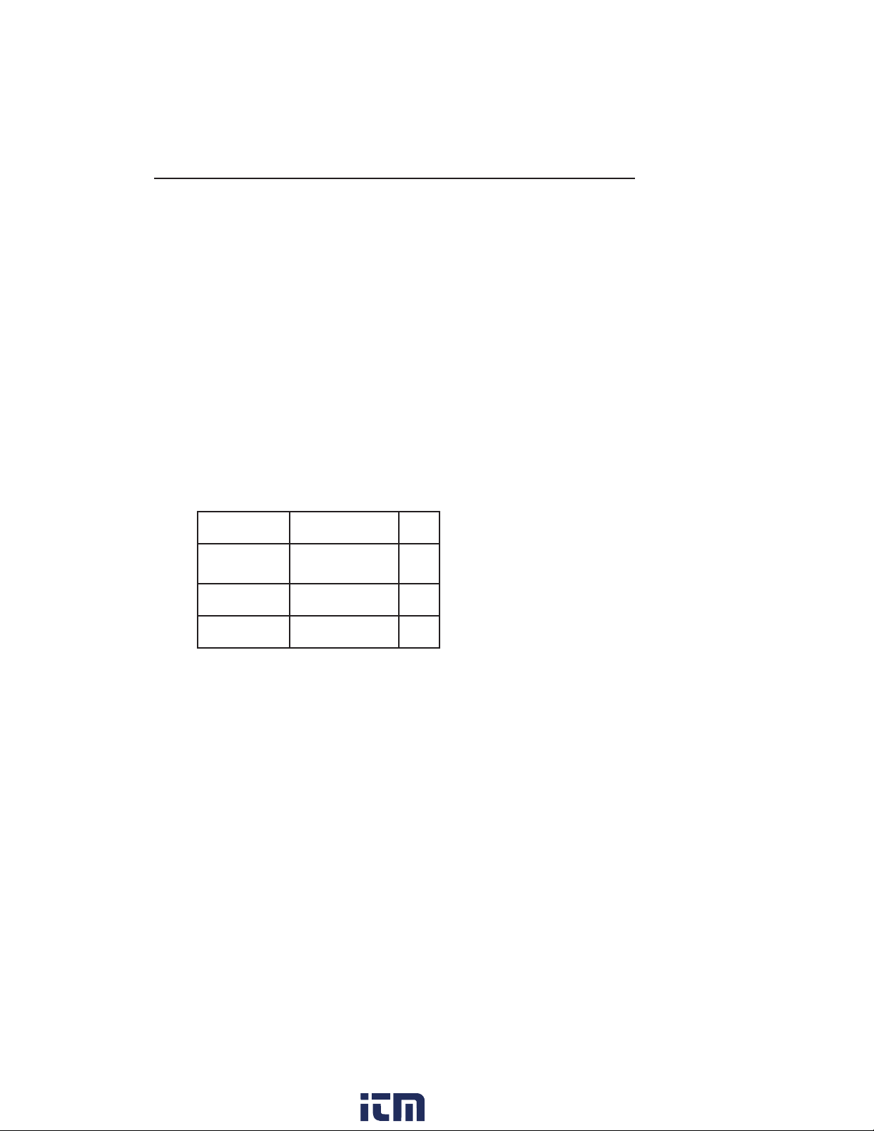
Replacement Parts
Cat. No./ UPC Description Qty
08728
08738 Carrying Case 1
08729 Main Power Cord 1
Test Lead Unit
with Case
1
21
www. .com
[email protected]1.800.561.8187
Page 22
Specifications
Accuracy
Accuracy is specified from -20°C to 40°C
Measurements
Note: All data regarding accuracy is given for nominal (reference) environment condition.
Insulation Resistance
Nominal test voltage: 250 V, 500 V, 1 kV, 2.5 kV, 5 kV
Current capability of test generator: >1 mA
Short-circuit test current: 5 mA.
Automatic discharge of tested object: Yes
Measuring Range Riso: 0.12 MΩ up to 999 GΩ*
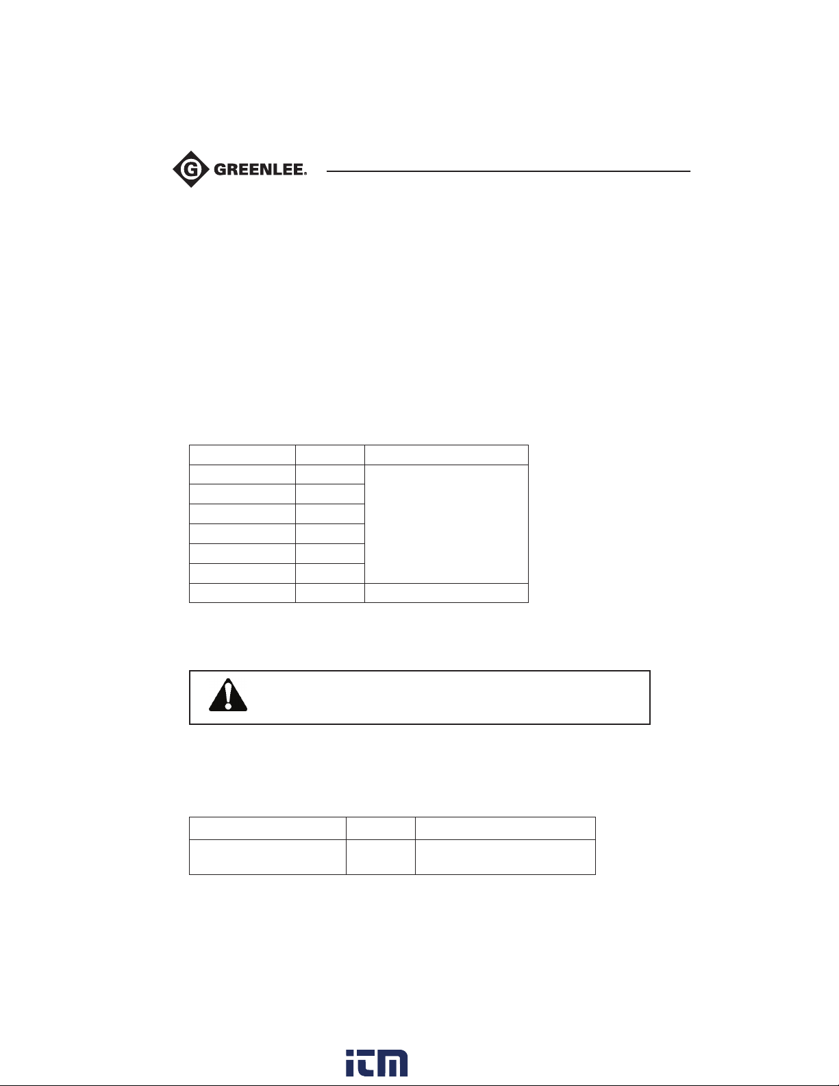
Display Range Resolution Accuracy
5 - 999 kΩ 1 kΩ
1.00 - 9.99 MΩ 10 kΩ
10.0 - 99.9 MΩ 100 kΩ
100 - 999 MΩ 1 MΩ
1.00 - 9.99 GΩ 10 MΩ
10.0 - 99.9 GΩ 100 MΩ
100 - 999 GΩ 1 GΩ ±(10 % of reading + 3 digits)
± (5 % of reading + 3 digits)
*Full-scale value of insulation resistance is defined according the following equation:
= 1GΩ * U
R
FS
DC test voltage:
Voltage value: 250V, 500V, 1kV, 2,5kV, 5kV.
Accuracy: -0 / +10 % + 20 V.
Output power: 5 W max.
Display range test voltage (V) Resolution Accuracy
22
[V] (if U
test
For insulation resistance value under 5 kΩ the instrument will desplay the value 0 Ω.
0 - 1999 kΩ
2.00k - 5.50k
> 1kV then R
test
FS
1 V
10V
= 1TΩ)
± (3 % of reading + 3 digits)
www. .com
[email protected]1.800.561.8187
Page 23
5990A
Specifications (cont’d)
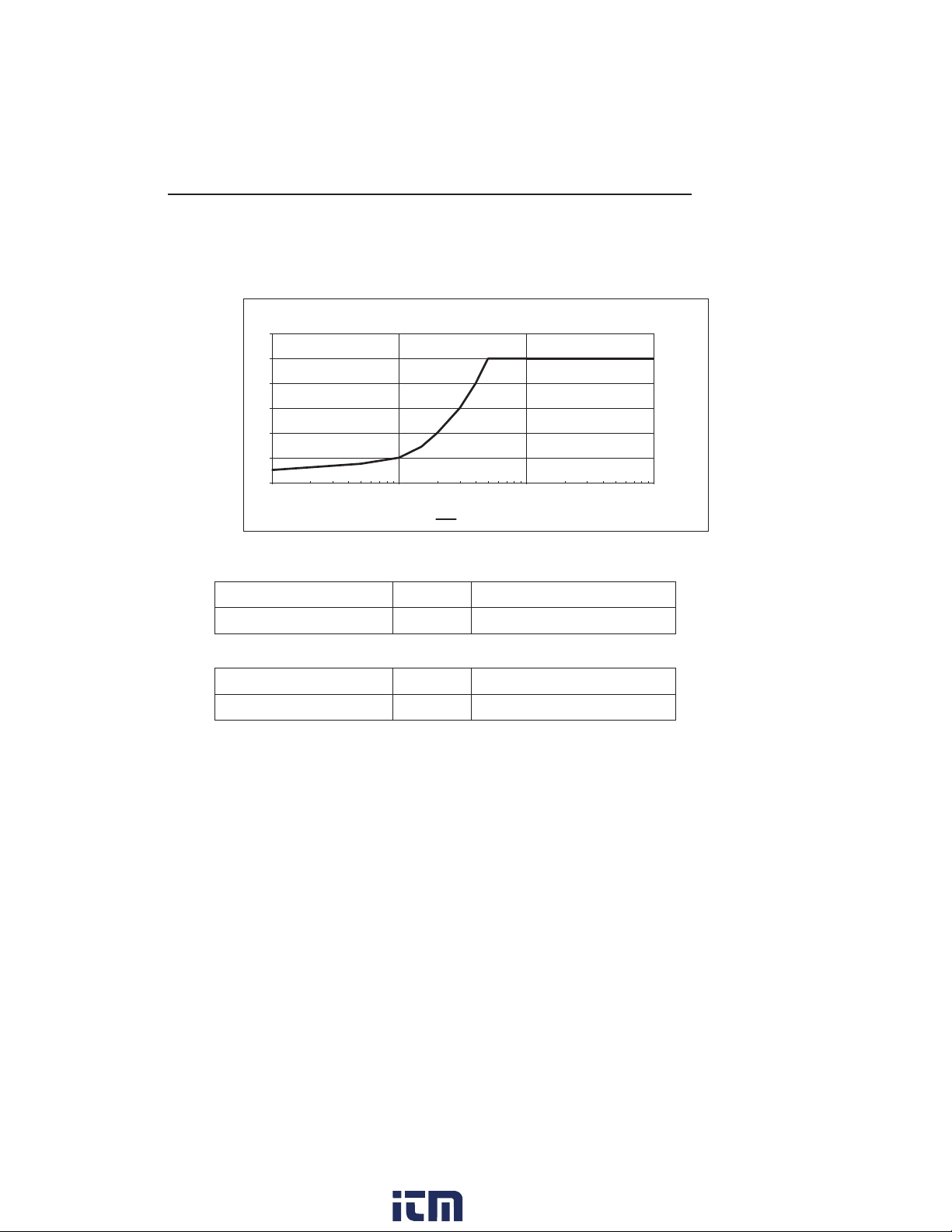
Generator Capability vs Resistance
6
5
4
3
[ kV ]
2
1
0
[ MΩ ]
Utest=5kV
Voltage
Voltage AC or DC
Display range test voltage (V) Resolution Accuracy
0 - 600 1 V ± (3 % of reading + 4 V)
Frequency of External Voltage
Display range test voltage (V) Resolution Accuracy
0 and 45 - 65 0.1 Hz ± 0.2 Hz
Note:
• For a frequency between 0 and 45 Hz frequency, result is shown as – – –
• For a frequency over 65 Hz frequency, result is shown as – – –
• For a voltages under 10V frequency, result is shown as – – –
0010111,0
Input resistance: 3 MΩ±10 %
www. .com
23
[email protected]1.800.561.8187
Page 24

General Specifications
Battery Power Supply..................................................................7.2 V DC (6 × 1.2 V NiMHC size)
Mains Power Supply...................................................................90-260 V AC, 45-65 Hz, 40 VA
Over-Voltage Category................................................................300 V CAT III
Protection Classification.............................................................Double Insulation
Measurement Category..............................................................600 V CAT IV
Pollution Degree.........................................................................2
Degree of Protection..................................................................IP 40 with case closed
Dimensions (w × h × d).............................................................31 cm x 13 cm x 25 cm
Weight (without accessories, with batteries).............................3 kg
Visual and Sound Warnings........................................................Yes
Display.......................................................................................LCD segments and
analog scale with backlight
Environment Conditions
Working Temperature Range...........................-10 - 50 °C
Nominal (reference) Temperature Range.........10 - 30 °C
Storage Temperature Range............................-20 - +70 °C.
Maximum Humidity ........................................90% RH (0 - 40 °C) non-condensing
Nominal (reference) Humidity Range...............40 - 60 % RH
Nominal Altitude.............................................Up to 2000m
Auto-Calibration
Auto-Calibration of Measuring System............Every time after turning power on
Connecting System
Two Safety Banana Sockets...........................+OUT, -OUT (5kV CAT I, Double)
Two GUARD Banana Sockets.......................GUARD (600V CAT IV, Double)
Guard Resistance...........................................200 kΩ ± 10 %
Discharging
Every time after measurement completion.
Discharging Resistance:.................................300 kΩ ± 10 %
24
www. .com
[email protected]1.800.561.8187
Page 25

5990A
Measurement Categories
These definitions were derived from the international safety standard for insulation coordination
as it applies to measurement, control, and laboratory equipment. These measurement categories
are explained in more detail by the International Electrotechnical Commission; refer to either of
their publications: IEC 61010-1 or IEC 60664.
Measurement Category I
Signal level. Electronic and telecommunication equipment, or parts thereof. Some examples
include transient-protected electronic circuits inside photocopiers and modems.
Measurement Category II
Local level. Appliances, portable equipment, and the circuits they are plugged into. Some examples include light fixtures, televisions, and long branch circuits.
Measurement Category III
Distribution level. Permanently installed machines and the circuits they are hard-wired to. Some
examples include conveyor systems and the main circuit breaker panels of a building’s electrical
system.
Measurement Category IV
Primary supply level. Overhead lines and other cable systems. Some examples include cables,
meters, transformers, and other exterior equipment owned by the power utility.
Statement of Conformity
Greenlee Tools, Inc. is certified in accordance with ISO 9000 (2000) for our
Quality Management Systems.
www. .com
25
[email protected]1.800.561.8187
 Loading...