

Page 1
INSTRUCTION MANUAL
0
8
5
7
0
7
5
6
0
6
5
5
0
5
5
4
0
4
5
3
0
3
5
2
0
2
5
1
0
1
5
0
5
0
1
™
555BAT
BATTERY-POWERED
BENDER
SERIAL CODE ACB
Read and understand this material before operating
or servicing this equipment. Failure to understand how
to safely operate this tool could result in an accident
causing serious injury or death.
999 2601.6 © 1999 Greenlee Textron IM 1321 REV 2 5/99
Page 2

Table of Contents
Description ............................................................................................................2
Purpose.................................................................................................................2
Important Safety Instructions .............................................................................3-5
Grounding Instructions for Charger.......................................................................6
Features ................................................................................................................7
Specifications ........................................................................................................8
Bending Attachment Groups .................................................................................9
Introduction .........................................................................................................10
Batteries ....................................................................................................10
Battery Charger .........................................................................................10
Preparation.....................................................................................................11-12
Setup ..................................................................................................................13
Operation .......................................................................................................14-16
Adjusting the Squeeze ..............................................................................16
Illustrated Bending Glossary ...............................................................................17
Bending Instructions.......................................................................................18-19
Additional Bending Instructions......................................................................20-22
Additional Bending Tables .............................................................................23-29
Maintenance...................................................................................................30-31
Chain Tension Adjustment ........................................................................30
Replacing the Fuse ...................................................................................30
Replacing the Battery ................................................................................31
Electrical Control Unit................................................................................31
Reductor Gearbox .....................................................................................31
Troubleshooting ..................................................................................................32
Exploded View ...............................................................................................33-35
Parts List ........................................................................................................36-38
Roller Support Units .......................................................................................39-40
Motor—24 Volt ....................................................................................................41
Control Assembly ...........................................................................................42-44
Bending Shoes and Roller Supports ..............................................................45-48
555BAT™ Battery-Powered Bender
Description
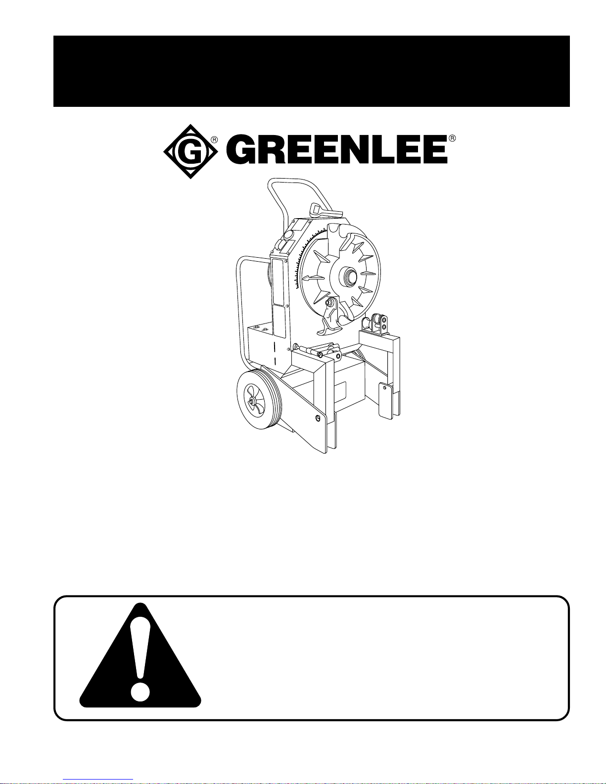
The Greenlee 555BAT™ Battery-Powered Bender is designed to provide conduit
and pipe bending capability where line power is inconvenient to use or unavailable.
The bender is balanced for ease of transportation, simple to use and operates quietly.
It is intended to bend 1/2" – 2" conduit and Schedule 40 steel pipe.
This manual also applies to the following models:
• 555RBAT™ (Model 05152, which includes Shoes for Rigid Steel Conduit or Schedule 40 Steel Pipe)
• 555EBAT™ (Model 05153, which includes Shoes for Electrical Metallic Tubing)
• 555IBAT™ (Model 05154, which includes Shoes for Intermediate Metallic Conduit)
The following bending attachments are available for the 555BAT™ Electric Bender:
• Greenlee Catalog Number 23802, for bending 1/2" – 2" Electrical Metallic Tubing
• Greenlee Catalog Number 23816, for bending 1-1/2" – 2" Electrical Metallic Tubing
• Greenlee Catalog Number 26330, for bending 1-1/2" – 2" Intermediate Metallic Conduit
• Greenlee Catalog Number 28007, for bending 1/2" – 2" Rigid Steel Conduit or Schedule 40 Steel Pipe
• Greenlee Catalog Number 37279, for bending 1/2" – 2" 40 Mil PVC– Coated Rigid Steel
Purpose
This instruction manual is intended to familiarize operators and maintenance
personnel with the safe operation and maintenance procedures for the Greenlee
555BAT™ Battery-Powered Bender. This manual should be kept available to all
operating and maintenance personnel.
Greenlee Textron / Subsidiary of Textron Inc.
2
4455 Boeing Dr., Rockford, IL 61109-2988 815/397-7070
Page 3
555BAT™ Battery-Powered Bender
IMPORTANT SAFETY INSTRUCTIONS
SAFETY
ALERT
Immediate hazards which, if not avoided, WILL result in
severe personal injury or death.
SYMBOL
The symbol above is used to call your attention
to instructions concerning your personal safety.
Watch for this symbol. It points out important safety
precautions. It means “ATTENTION! Become alert!
Your personal safety is involved!” Read the
message that follows and be alert to the possibility
of personal injury or death.
Safety is a critical factor in the design of Greenlee equipment. The best program starts with a safety-conscious
operator. The information highlighted in this bulletin describes operating practices for the benefit of the workers
who will use our equipment in their daily jobs. Comments from users are appreciated.
A person who has not read and does not understand all
operating instructions is not qualified to operate this tool.
Failure to read and understand safety instructions could
result in injury or death.
Hazards or unsafe practices which, if not avoided, COULD
result in severe personal injury or death.
Hazards or unsafe practices which, if not avoided, COULD
result in minor personal injury or property damage.
SA VE THESE INSTRUCTIONS
Additional copies of this manual are available upon request at no charge.
Greenlee Textron / Subsidiary of Textron Inc.
3
4455 Boeing Dr., Rockford, IL 61109-2988 815/397-7070
Page 4
555BAT™ Battery-Powered Bender
IMPORTANT SAFETY INSTRUCTIONS
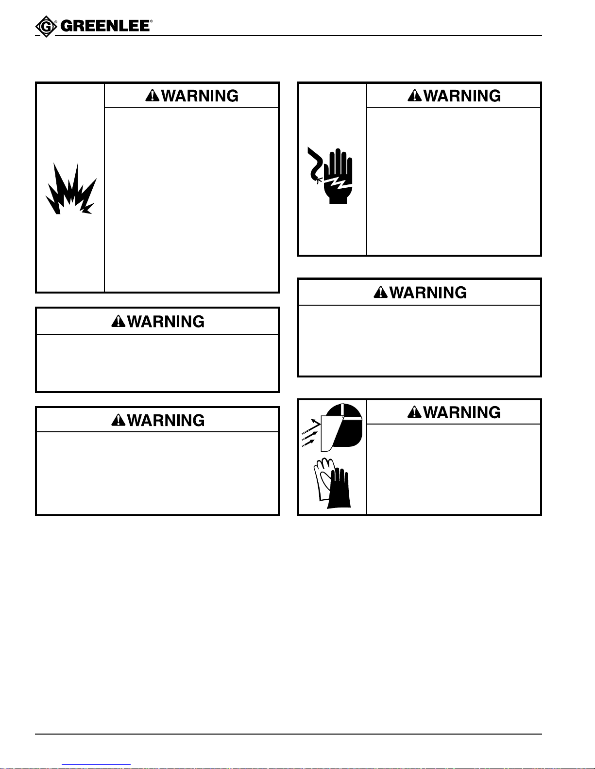
Batteries can produce explosive
hydrogen gas.
• Use this bender in well-ventilated
areas.
• Do not allow metal or conductive
objects to contact the battery
terminals.
• Use insulated tools when connect-
ing or disconnecting battery
cables.
• Do not use this bender near an
open flame.
Failure to observe these warnings
will result in severe injury or death.
Do not use automotive batteries. Use only
PowerSonic Model PS-12600 or equivalent deep
cycle-type batteries. Other batteries can overheat,
explode or vent explosive hydrogen gas.
Electric shock hazard:
• Do not modify the charger power
cord or plug.
• Inspect the charger power cord
before connecting to a power
source.
• Connect the charger power cord
to a 120V, 15-amp grounded
receptacle only.
Failure to observe these warnings
can result in severe injury or death.
Do not attempt to charge a very cold or frozen
battery. Damage to the battery could result,
causing acid to spray out.
Failure to observe this warning can result in
severe injury or death.
Keep terminal covers in place and the battery
compartment closed during operation and storage.
The battery compartment must be closed to protect
the batteries and battery cables from damage.
Failure to observe this warning can result in severe
injury or death.
SA VE THESE INSTRUCTIONS
Additional copies of this manual are available upon request at no charge.
Batteries contain acid. Wear rubber
gloves and face shield. Use insulated tools when inspecting or
working with the batteries.
Failure to observe this warning can
result in severe injury.
Greenlee Textron / Subsidiary of Textron Inc.
4
4455 Boeing Dr., Rockford, IL 61109-2988 815/397-7070
Page 5
555BAT™ Battery-Powered Bender
IMPORTANT SAFETY INSTRUCTIONS
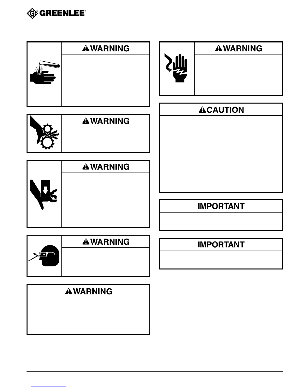
Replacement batteries must be
rated by the battery manufacturer for
use in any position. Other batteries
may leak acid when the bender is
transported or used in the horizontal
bending position.
Failure to observe this warning can
result in severe injury or death.
Do not remove guards.
Failure to observe this warning can
result in severe injury or death.
Pinch points.
• Turn bender OFF before changing
accessories. Accidental start-up
can result in serious injury.
• Keep hands away from bending
shoe and rollers when bender is in
use. Conduit at the bending shoes
and rollers can crush a hand.
Before servicing: turn bender OFF,
disconnect the charger from the
power source and disconnect
battery cables.
Failure to observe this warning can
result in severe injury or death.
• Inspect the bender before using. Replace
worn, damaged or missing parts with Greenlee
replacement parts. A damaged or improperly
assembled component could break and strike
nearby personnel.
• Do not overbend conduit or pipe. Overbending
could cause conduit to run out of shoe groove
resulting in damage to the bender.
• Use the bender for manufacturer’s intended
purpose only. Use other than that which is
described in this manual can result in injury
or property damage.
Read the Material Safety Data Sheet for Sealed
Maintenance Free Lead Acid Batteries.
Wear eye protection when operating
the bender. Failure to wear eye
protection can result in serious eye
injury from flying debris.
Do not wear loose clothing when operating
the bender. Loose clothing can get caught in
moving parts.
Failure to observe this warning can result in
severe injury or death.
SA VE THESE INSTRUCTIONS
Additional copies of this manual are available upon request at no charge.
Greenlee Textron / Subsidiary of Textron Inc.
Follow the operating instructions and safety
information supplied with the battery charger.
5
4455 Boeing Dr., Rockford, IL 61109-2988 815/397-7070
Page 6
555BAT™ Battery-Powered Bender
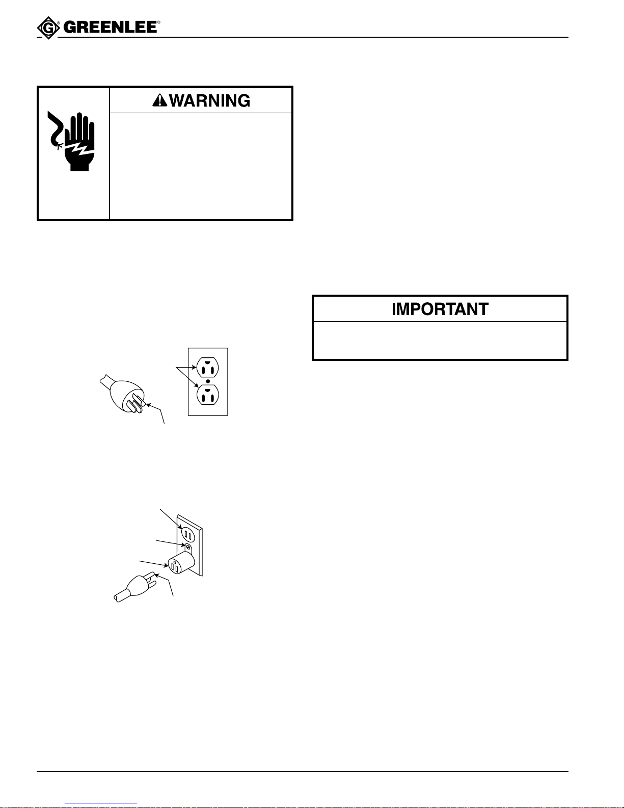
Grounding Instructions for Charger
Electric shock hazard:
• Do not modify the plug provided
with the charger.
•
Connect the charger to a grounded
receptacle on a 15-amp circuit.
Failure to observe these warnings
can result in severe injury or death.
The charger must be grounded. In the event of a
malfunction or breakdown, an electrical ground provides
a path of least resistance for the electric current. This
path of least resistance is intended to reduce the risk of
electric shock.
Figure 1
Plug and Grounded Receptacle
GROUNDED
RECEPTACLES
The charger’s electric cord has a grounding conductor
and a grounding plug as shown. Do not modify the
plug. Connect the plug to a 15-amp GFCI protected
receptacle that is properly installed and grounded
in accordance with all national and local codes
and ordinances.
The charger is intended for use with a three-wire
grounded GFCI protected circuit. A temporary adapter
may be used to connect the charger to a two-wire
circuit. See the illustration. The green-colored ear
or lug extending from the adapter must be connected
to a permanent ground, such as a properly grounded
receptacle box or water pipe. The grounding lug or
wire must be held in place by a metallic screw or
clamp. A temporary adapter should be used only until
a properly-grounded receptacle can be installed by
a qualified electrician.
The Canadian Electric Code does not permit the use
of a temporary adapter.
GROUNDING PIN
Figure 2
Plug and Grounded Receptacle with Temporary Adapter
GROUNDED
RECEPTACLE
METALLIC
SCREW
ADAPTER
GROUNDING PIN
Greenlee Textron / Subsidiary of Textron Inc.
6
4455 Boeing Dr., Rockford, IL 61109-2988 815/397-7070
Page 7
555BAT™ Battery-Powered Bender
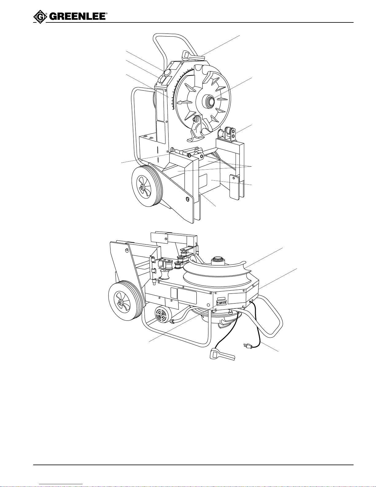
Features
1
2
3
0
8
5
7
0
7
5
6
0
6
5
12
5
0
5
5
4
0
4
5
3
0
3
5
2
0
2
5
1
0
1
5
0
5
10
13
7
4
6
5
Secure the battery compartment by attaching
a lock at the hole behind this leg.
11
1. Pendant Switch
2. Battery Gauge
3. Battery Gauge Switch
4. Spare Roller Support Storage
5. Lockable Battery Compartment
6. 12-Volt Batteries
7. Roller Support
10
9
8
8. Battery Charger Power Cord
9. Bending Instructions Decal
10. Bending Shoe
11. Circuit Breaker (ON/OFF Switch)
12. Degreed Protractor
13. Main Shaft
Greenlee Textron / Subsidiary of Textron Inc.
7
4455 Boeing Dr., Rockford, IL 61109-2988 815/397-7070
Page 8

Specifications
555BAT™ Battery-Powered Bender:
Battery Charger:
Batteries:
555BAT™ Battery-Powered Bender
Height .................................................................................49-1/2 in. (126 cm)
Width ....................................................................................28-1/2 in. (72 cm)
Depth ....................................................................................26-1/2 in. (67 cm)
Weight (without Bending Shoe) .............................................. 410 lbs (186 kg)
Operating Temperature Range............................ -4° to 120° F (-20° to 48° C)
Operating Humidity Range ....................................0 to 98% Relative Humidity
Capacity...................................................1/2" – 2" Conduit, Schedule 40 Pipe
Voltage .................................................................................. 115 VAC (
Frequency........................................................................................ 50 / 60 Hz
Current Draw ........................................................................................ 2 amps
Power Source ........................................... 15 amp GFCI-protected receptacle
Type............................. PowerSonic Model PS-12600 Deep Cycle, Group 24
Connector ...............................Lug Type Terminator with 5/16" Diameter Hole
Voltage ................................................................................................12 Volts
Current Rating ............................................................ 60 Amp-Hours Nominal
Quantity ..........................................................................................................2
Operating and Charging Temperature Range ..... -4° to 120° F (-20° to 48° C)
±
20%)
Greenlee Textron / Subsidiary of Textron Inc.
8
4455 Boeing Dr., Rockford, IL 61109-2988 815/397-7070
Page 9
555BAT™ Battery-Powered Bender
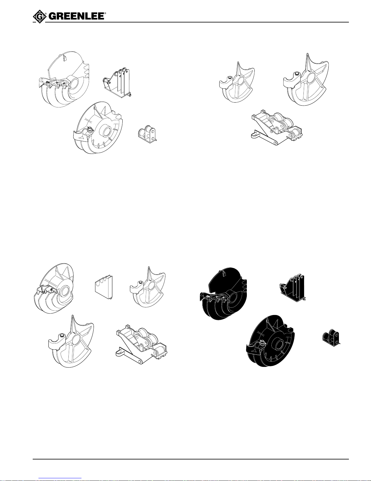
Bending Attachment Groups
Rigid
21
34
28007: 1/2" – 1-1/4" IMC
1/2" – 2" Rigid Steel
1/2" – 2" Schedule 40 Pipe
UPC No.
Key 78-3310- Description
1 00571 Bending Shoe for 1/2" – 1-1/4"
2 00936 Roller Support Unit for 1/2" – 1-1/4"
3 17937 Bending Shoe for 1-1/2" – 2"
4 17984 Roller Support Unit for 1-1/2" – 2"
IMC
1 2
3
26330: 1-1/2" – 2" IMC
UPC No.
Key 78-3310- Description
1 25263 Bending Shoe for 1-1/2"
2 25268 Bending Shoe for 2"
3 25273 Roller Support Unit for 1-1/2" – 2"
23818 Storage Box
EMT
1 2
4 5
23802: 1/2" – 2" EMT
UPC No.
Key 78-3310- Description
1 17944 Bending Shoe for 1/2" – 1-1/4"
2 17986 Roller Support Unit for 1/2" – 1-1/4"
3 23499 Bending Shoe for 1-1/2"
4 23505 Bending Shoe for 2"
5 23541 Roller Support Unit for 1-1/2" – 2"
23818 Storage Box
3
PVC-Coated Rigid
12
3 4
37279: 1-1/2" – 2" 40 Mil PVC-Coated Rigid
UPC No.
Key 78-3310- Description
1 00573 Bending Shoe for 1/2" – 1-1/4"
2 00946 Roller Support Unit for 1/2" – 1-1/4"
3 37281 Bending Shoe for 1-1/2" – 2"
4 37282 Roller Support Unit for 1-1/2" – 2"
23818 Storage Box
Greenlee Textron / Subsidiary of Textron Inc.
9
4455 Boeing Dr., Rockford, IL 61109-2988 815/397-7070
Page 10
Introduction
555BAT™ Battery-Powered Bender
555BAT™ Battery-Powered Bender
The 555BAT™ is intended to bend 1/2" – 2" conduit
and Schedule 40 pipe. The bender can be used in either
the vertical or horizontal bending positions. With fresh,
fully-charged batteries, the bender can perform over
100 bends in 2" rigid steel or IMC conduit.
The bender is equipped with two 12-volt batteries and
an onboard battery charger. A battery gauge with a
switch allows the operator to determine the charge level
of each battery. The bender can be used while charging
is in progress. The battery compartment is lockable to
prevent theft of the batteries.
Batteries
Two rechargeable 12-volt deep cycle batteries are
standard equipment on the 555BAT™ Battery-Powered
Bender. The batteries are connected in series to provide
24 volts to the bender. The batteries are intended for
use in any position, so the bender can be used to bend
in the vertical or horizontal bending positions.
To get the best performance from the batteries:
• Charge the batteries before first use.
• Charge the batteries after partial discharge rather
than after full discharge.
• Store the batteries at full charge; recharge every
6 months.
• Store the batteries at 68° to 77° F (20° to 25° C).
Batteries contain hazardous chemicals and produce
explosive hydrogen gas. Refer to the Material Safety
Data Sheet for Sealed Maintenance Free Lead Acid
Batteries for further safety information.
When replacement is necessary, replace with two
PowerSonic Model PS-12600 batteries, or equivalent
batteries with the following characteristics:
• 12-volt
• sealed construction
• rated by the manufacturer for use in any position
• deep-cycle type
• capacity of 60 amp-hours nominal
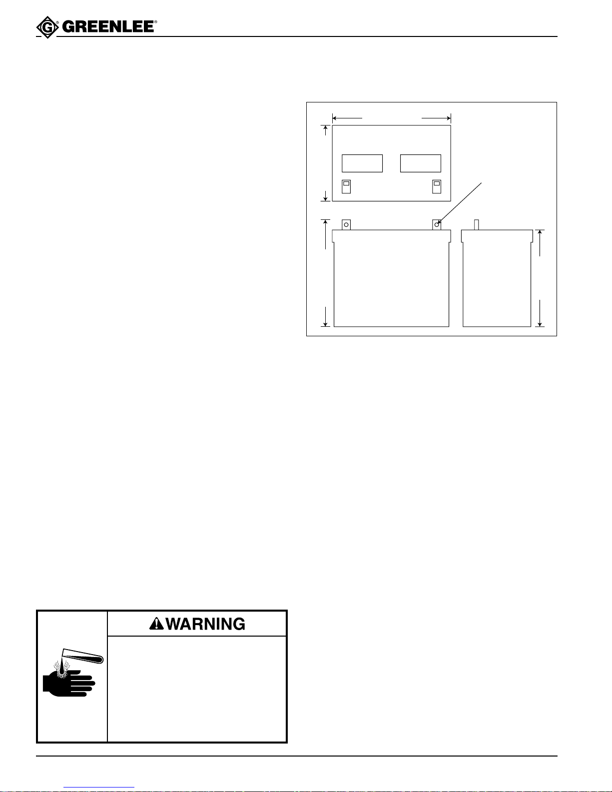
• dimensions as illustrated
Battery Dimensions (Maximum)
10-3/8" (26.3 cm)
Hole Diameter to be
Suitable for 5/16" Bolt
7-3/8" (18.7 cm)
9" (22.8 cm)
10.25" (26 cm)
Battery Charger
The onboard battery charger will charge new, fully
discharged 60 amp-hour batteries in 12 hours or less.
Larger batteries require more time to recharge. After
the batteries are fully charged, the charger switches
to a “float” mode to prevent overcharging the batteries.
The float mode will keep the batteries at full charge
indefinitely without overcharging.
The charger can be used while bending is in progress.
Note: Using the bender continuously to bend large
diameter conduit while charging will deplete
the batteries faster than the charger can
charge them.
See the battery charger instruction manual for a
complete set of safety information and operating
instructions.
Replacement batteries must be
rated by the battery manufacturer for
use in any position. Other batteries
may leak acid when the bender is
transported or used in the horizontal
bending position.
Failure to observe this warning can
result in severe injury or death.
Greenlee Textron / Subsidiary of Textron Inc.
10
4455 Boeing Dr., Rockford, IL 61109-2988 815/397-7070
Page 11
Preparation
555BAT™ Battery-Powered Bender
Batteries can produce explosive
hydrogen gas.
• Use this bender in well-ventilated
areas.
• Do not allow metal or conductive
objects to contact the battery
terminals.
• Do not use this bender near an
open flame.
Failure to observe these warnings
will result in severe injury or death.
Electric shock hazard:
• Do not modify the charger power
cord or plug.
• Inspect the charger power cord
before connecting to a power
source.
• Connect the charger power cord
to a 120V, 15-amp grounded
receptacle only.
Failure to observe these warnings
can result in severe injury or death.
Batteries contain acid. Wear rubber
gloves and face shield. Use insulated tools when inspecting or
working with the batteries.
Failure to observe this warning can
result in severe injury.
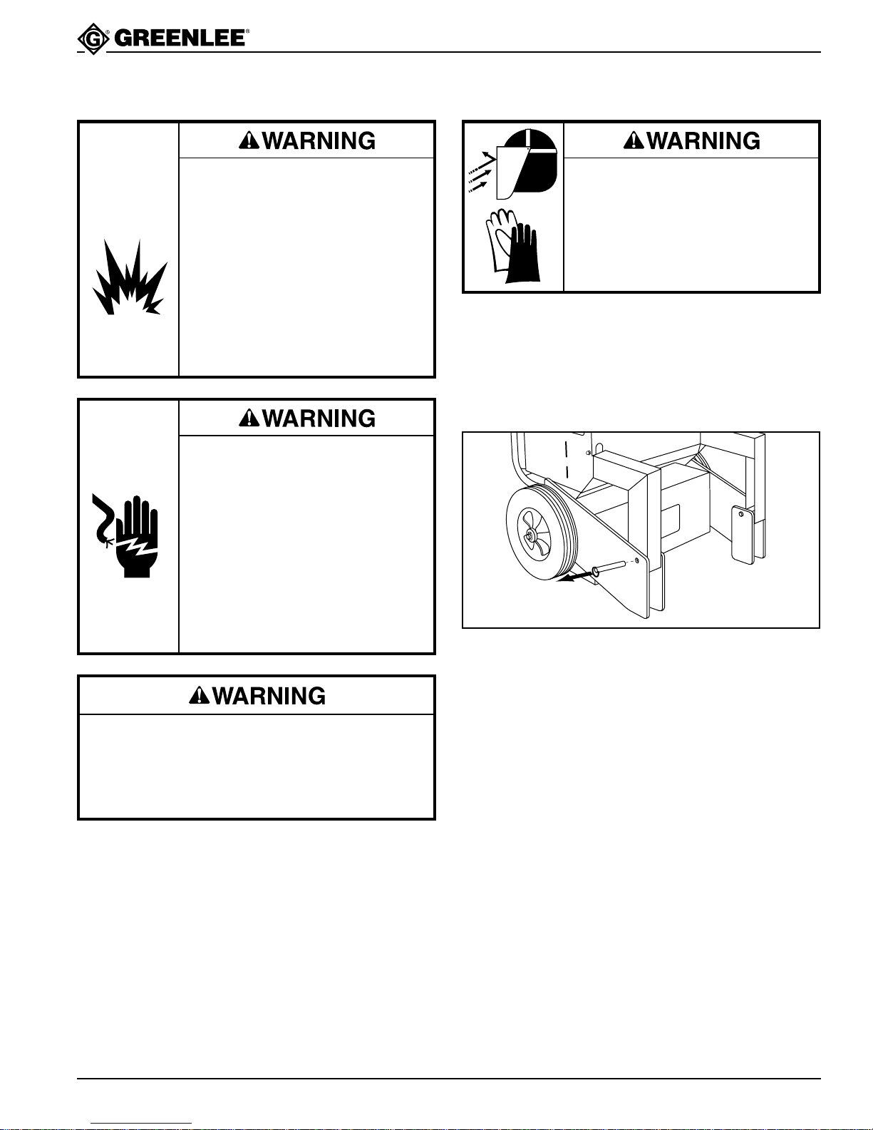
1. Place the bender on a firm level dry surface.
2. Check the circuit breaker to be sure it is in the
OFF position.
3. Remove the pins from the bender.
Removing the Pins
Do not attempt to charge a very cold or frozen
battery. Damage to the battery could result,
causing acid to spray out.
Failure to observe this warning can result in
severe injury or death.
Greenlee Textron / Subsidiary of Textron Inc.
11
4455 Boeing Dr., Rockford, IL 61109-2988 815/397-7070
Page 12
Preparation (cont’d)
555BAT™ Battery-Powered Bender
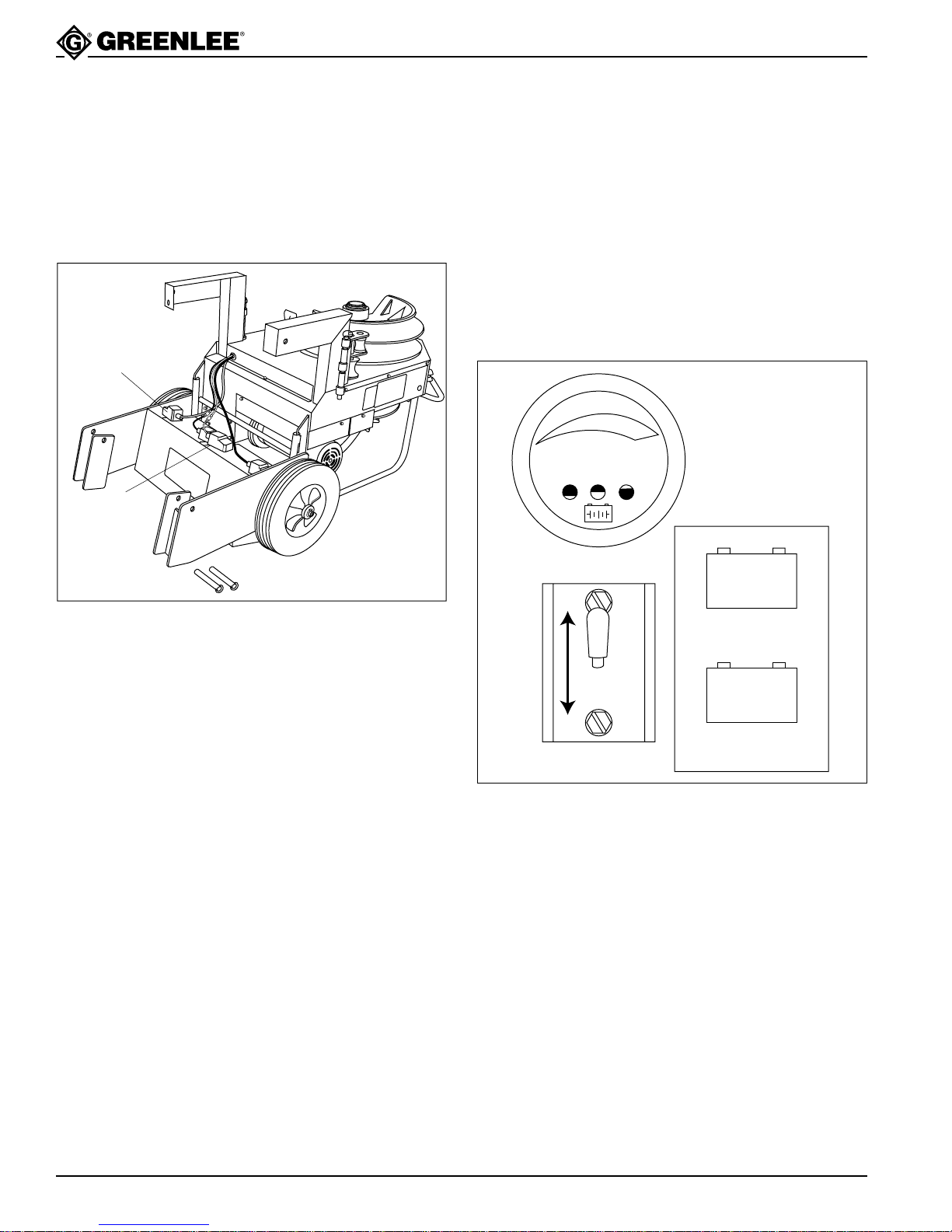
4. Tilt the top of the bender back to expose the battery
compartment. Remove the wire ties and connect the
red cable to the positive (+) terminal and the black
cable to the negative (–) terminal. Connect the black
negative cable last.
Connecting the Cables
Red Cable to
Positive Terminal
Black Cable to
Negative Terminal
6. Allow the batteries to charge for approximately
one hour.
7. Unplug the charger’s power cord.
8. Use the battery gauge switch to select Battery #1
and Battery #2. When the batteries are at full
charge, the bender is ready to use.
Note: The charger must be unplugged when
checking the battery charge level.
Using the Battery Gauge and Battery Gauge Switch
EMPTY FULL
% OF CHARGE
BATTERY GAUGE
5.
To protect the battery cables from damage, place
the excess wire into the space between the batteries
and the side of the battery compartment.
BATTERY 2
BATTERY 1
DECAL NO. 500 5143.1
Greenlee Textron / Subsidiary of Textron Inc.
12
4455 Boeing Dr., Rockford, IL 61109-2988 815/397-7070
Page 13
Setup
555BAT™ Battery-Powered Bender
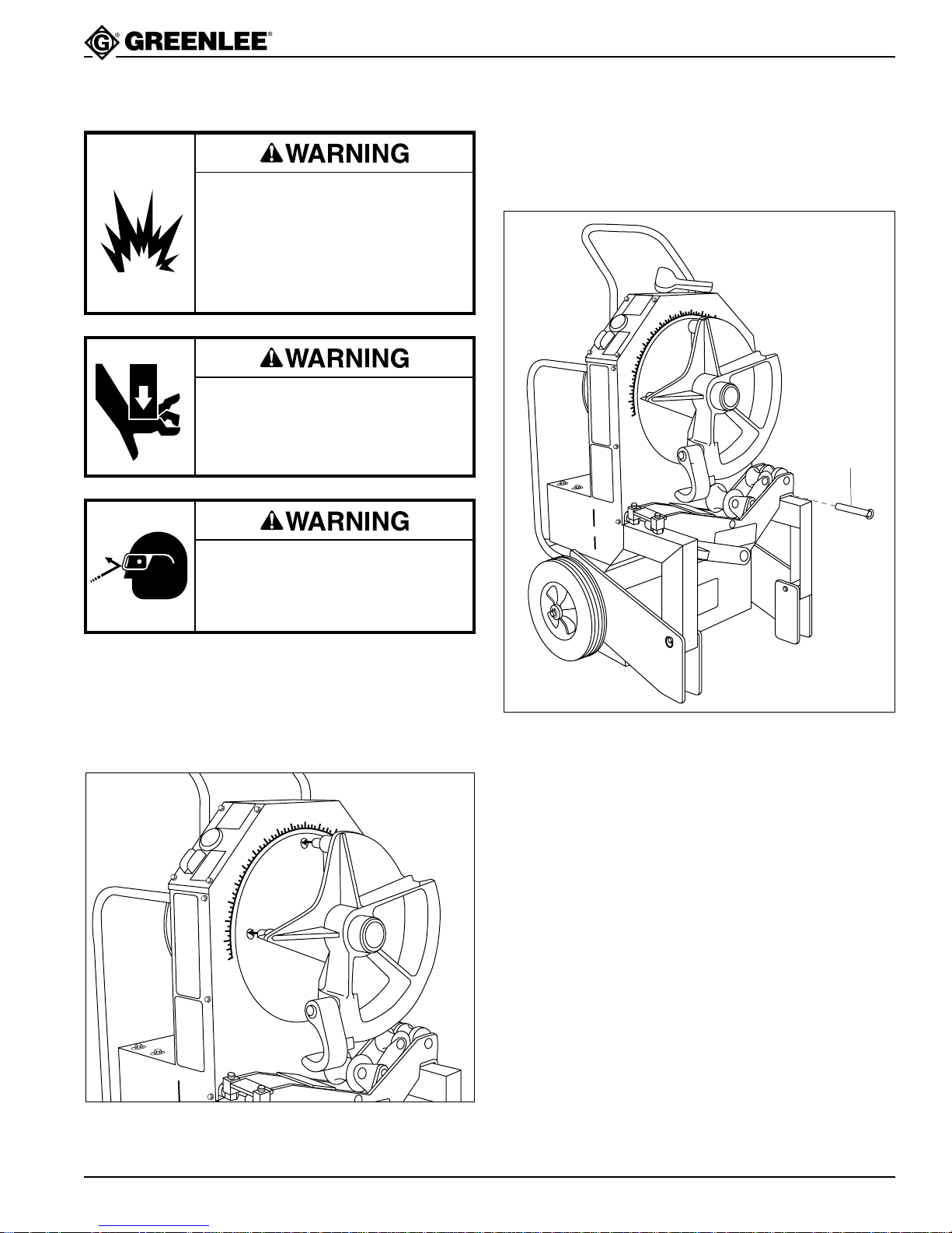
2. Mount the appropriate support unit onto the leg of
the bender and install the hinge pin, as shown.
Batteries can produce explosive
hydrogen gas.
Do not use this bender near an
open flame.
Failure to observe these warnings
will result in severe injury or death.
Pinch points.
Turn bender OFF before changing
accessories. Accidental start-up can
result in serious injury.
Wear eye protection when operating
the bender. Failure to wear eye
protection can result in serious eye
injury from flying debris.
Roller Support Unit Installed
0
9
1
0
0
9
0
5
5
8
8
1
1
0
5
1
5
7
0
7
5
6
0
6
5
5
0
5
5
4
0
4
5
3
0
3
5
2
0
2
5
1
0
1
5
0
5
10
0
1
1
1
5
2
0
1
2
5
1
3
0
1
3
5
1
4
0
1
Install pin.
1. Slide the appropriate bending shoe onto the shaft of
the main sprocket, as shown. Align the four drive
studs on the back of the shoe with the four holes in
the main sprocket.
Installing a Bending Shoe
0
1
9
0
0
9
5
0
5
8
8
1
1
0
5
5
7
0
7
5
6
0
6
5
5
0
5
5
4
0
4
5
3
0
3
5
2
0
2
5
1
0
1
5
0
5
10
1
0
1
1
1
5
2
0
1
2
5
1
3
0
1
3
5
1
4
0
1
5
3. Mark the conduit. See the decals on the bender or
the Additional Bending Instructions section of this
manual.
4. Place the bender in either the vertical or horizontal
bending position.
Greenlee Textron / Subsidiary of Textron Inc.
13
4455 Boeing Dr., Rockford, IL 61109-2988 815/397-7070
Page 14
555BAT™ Battery-Powered Bender
Operation
Keep terminal covers in place and the battery
compartment closed during operation and storage.
The battery compartment must be closed to protect
the batteries and battery cables from damage.
Failure to observe this warning can result in severe
injury or death.
Do not remove guards.
Failure to observe this warning can
result in severe injury or death.
1. Turn the Power Switch/Circuit Breaker to ON.
2. Press BEND or UNLOAD until the shoe is
5° – 10° before the 0° starting point.
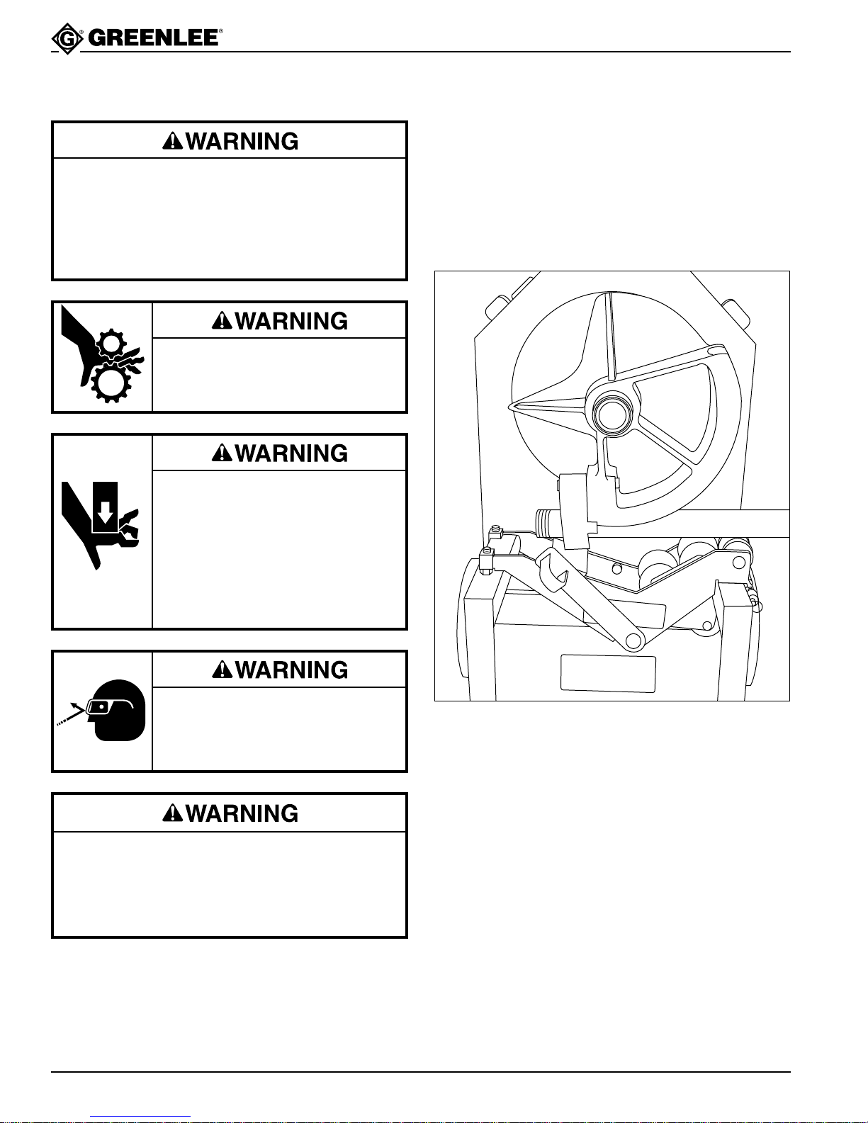
3. Load the conduit so that the bending mark is
aligned with the front edge of the shoe hook, as
illustrated.
Loading the Conduit
Pinch points.
• Turn bender OFF before changing
accessories. Accidental start-up
can result in serious injury.
• Keep hands away from bending
shoe and rollers when bender is in
use. Conduit at the bending shoes
and rollers can crush a hand.
Wear eye protection when operating
the bender. Failure to wear eye
protection can result in serious eye
injury from flying debris.
Do not wear loose clothing when operating
the bender. Loose clothing can get caught in
moving parts.
Failure to observe this warning can result in
severe injury or death.
4. See the instruction decal for the appropriate bend
angle.
Greenlee Textron / Subsidiary of Textron Inc.
14
4455 Boeing Dr., Rockford, IL 61109-2988 815/397-7070
Page 15
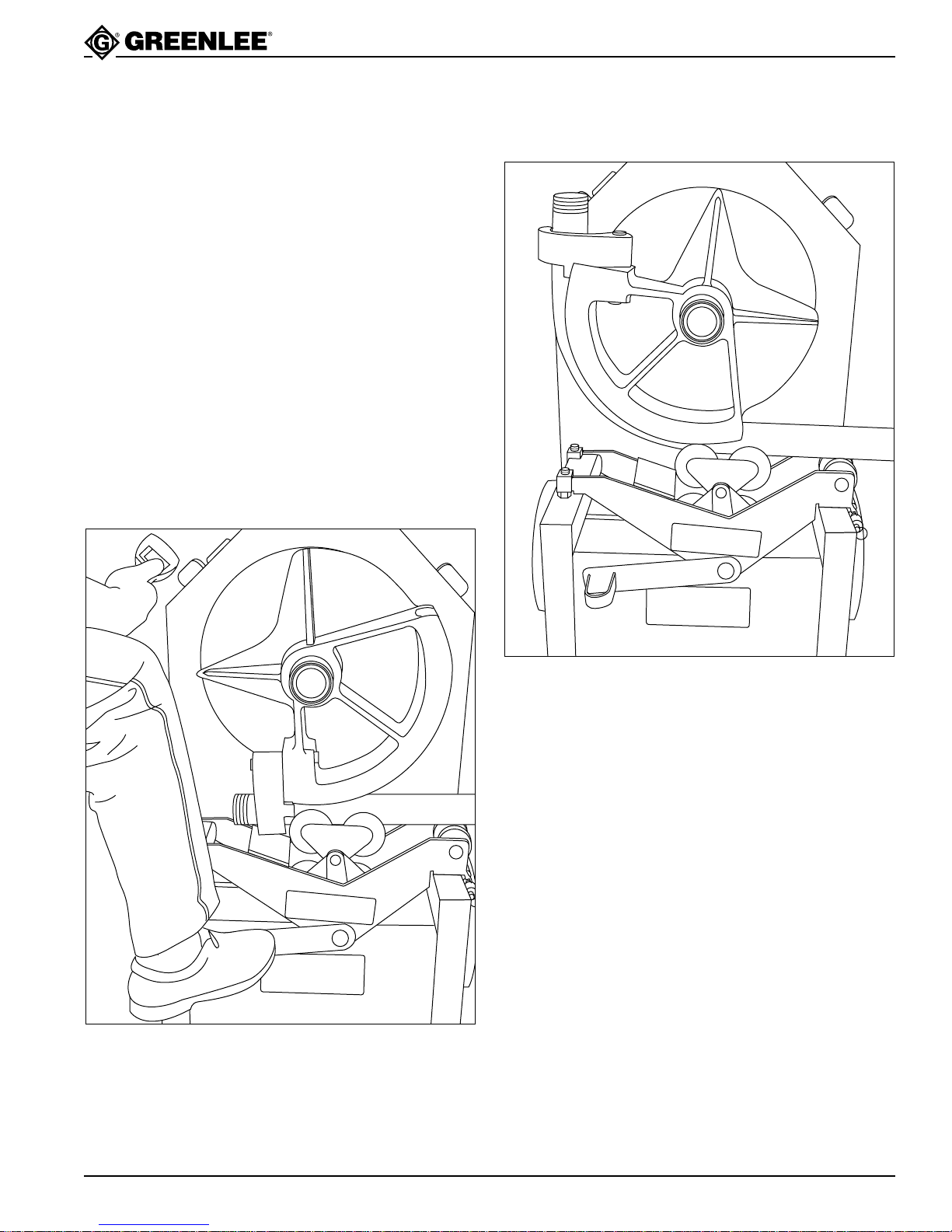
Operation (cont’d)
555BAT™ Battery-Powered Bender
5. Bend the conduit:
If bending 1-1/2" – 2" EMT or IMC:
a. Place one foot on the loading pedal, as shown.
b. Press and hold BEND. The bender will pull up the
roller support. When the roller support contacts the
stop, remove your foot from the loading pedal.
c. Release the BEND key as you approach the desired
angle of bend.
d. Press BEND momentarily until the bend is
complete.
If bending any other size or type of conduit:
e. Press and hold BEND.
f. Release the BEND key as you approach the desired
angle of bend.
g. Press BEND momentarily until the bend is
complete.
Engaging the Loading Pedal
(for 1-1/2" – 2" EMT or IMC Only)
Finished Bend
6. Unload the Bender.
a. Press UNLOAD. The shoe will rotate and drop the
Roller Support Unit (EMT and IMC only).
b. Twist the conduit to release it from the hook.
Remove the conduit.
c. Press and hold UNLOAD until the shoe has rotated
back to 0°.
Greenlee Textron / Subsidiary of Textron Inc.
15
4455 Boeing Dr., Rockford, IL 61109-2988 815/397-7070
Page 16
Operation (cont’d)
555BAT™ Battery-Powered Bender
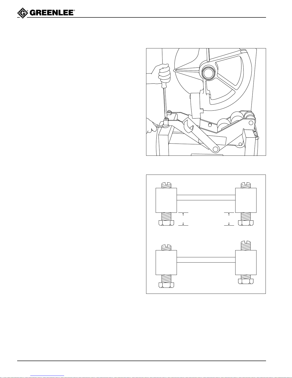
Adjusting the Squeeze
When bending 1-1/2" – 2" EMT or IMC, the roller
support must be engaged so that it contacts the conduit;
the pressure against the conduit is the “squeeze”.
Due to variations in conduit, the standard adjustment
may provide too much or too little squeeze. If the
conduit develops excessive side marking when bent,
the squeeze is set too high. If the conduit becomes
excessively oval or wrinkled, the squeeze is set too low.
1. Use a screwdriver to loosen the set screws.
2. Use a wrench to rotate both adjusting bolts 1/2 turn
clockwise to INCREASE squeeze or 1/2 turn
counterclockwise to DECREASE squeeze.
Note: In order to distribute the load evenly,
adjust both bolts to the same setting.
See the illustration.
3. Tighten the set screws.
Adjusting the Squeeze
Standard Squeeze Setting
Adjusting Bolts are
at the Same Setting
5/8" 5/8"
Adjusting Bolts are
at Different Settings
INCORRECT
Greenlee Textron / Subsidiary of Textron Inc.
16
4455 Boeing Dr., Rockford, IL 61109-2988 815/397-7070
Page 17
555BAT™ Battery-Powered Bender
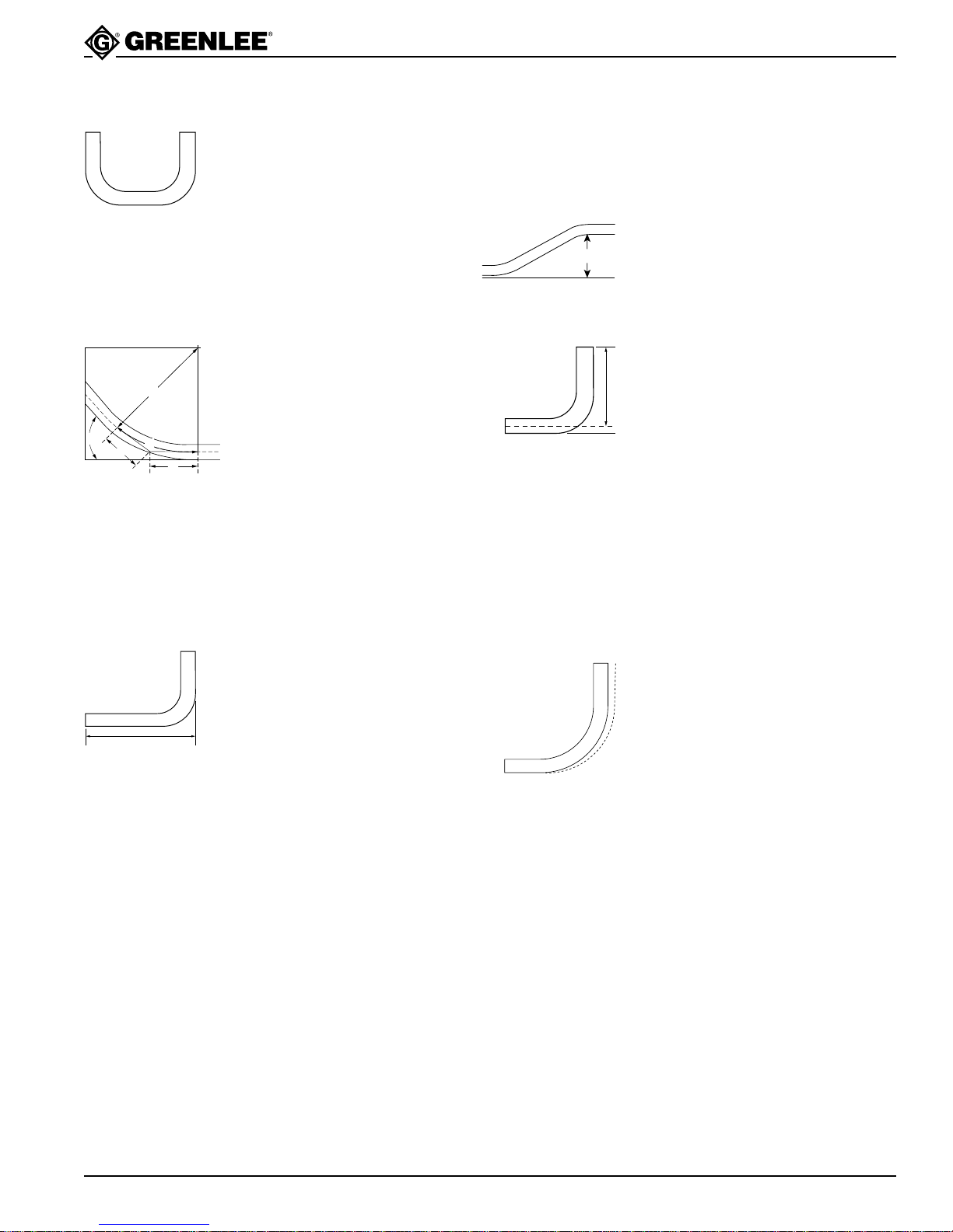
Illustrated Bending Glossary
1. back-to-back bend — any
U-shaped bend formed by two
parallel 90-degree bends with
a straight section of conduit or
7. offset bend — two opposite
bends with the same degree
of bend; used to avoid an
obstruction
pipe between the bends
8. offset height — the distance
2. center-to-center distance —
the distance between the
Offset Height
successive bends that make
up an offset or a three-bend
saddle
3. developed length — the actual
length of pipe that will be bent;
r
see distance “d” in the
illustration at left
between the two legs of
an offset bend, measured
perpendicular to the two legs;
also called amount of offset
and depth of offset
9. rise — the distance from the
end of a straight section of
conduit or pipe to the bend;
measured from the end to
the center line of the conduit
θ
d
a
a
4. gain — the difference between
the straight-line distance (a + a)
and the shorter radial distance,
(d) where:
θ = angle of bend
or pipe. Also called stub or
stub-up.
10. saddle — a three-bend or
four-bend combination; used
to avoid an obstruction
r = the centerline bending
radius of the bending shoe
11. shrink — the amount of conduit
“lost” when laying out an offset
5. kick — single bend of less
than 90°
bend working toward an
obstruction; see the explanation
under Offset Bending in
6. leg length — the distance from
this manual
the end of a straight section of
conduit or pipe to the bend;
measured from the end to the
outside edge of the conduit
or pipe.
12. springback — the amount,
measured in degrees, that a
conduit or pipe tends to
straighten after being bent
Greenlee Textron / Subsidiary of Textron Inc.
17
4455 Boeing Dr., Rockford, IL 61109-2988 815/397-7070
Page 18
555BAT™ Battery-Powered Bender
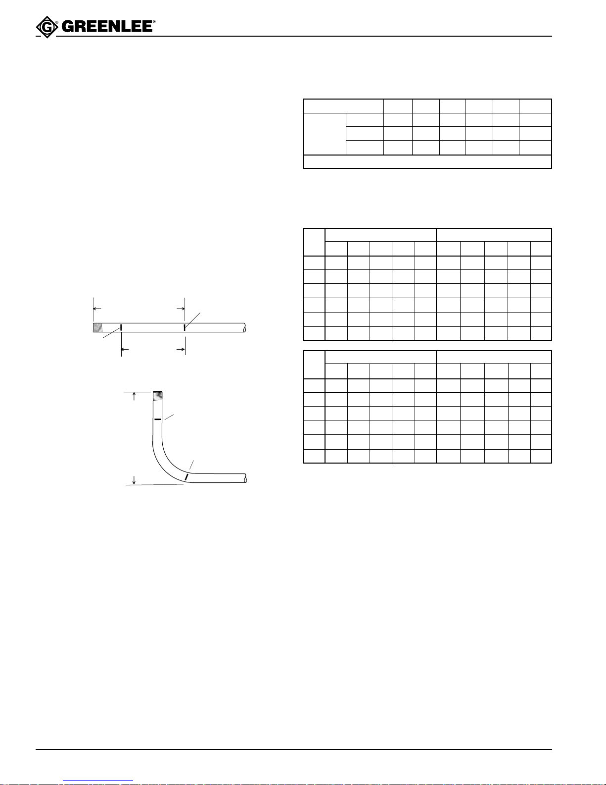
Bending Instructions
90° Stubs
1. Measure the length of the required stub.
2. See the Minimum Stub Length formula on the
Deduct Table. The required stub must be equal to
or longer than the Minimum Stub Length.
3. Measure and mark the stub length on the conduit.
This is Mark 1. Subtract the Deduct from this mark
and make a new mark. This is Mark 2.
4. Align Mark 2 with the front edge of the hook and
bend the conduit.
Note: When the operator presses “UNLOAD”,
the conduit may spring back a few degrees.
Compensate by overbending as shown in
the Scale Reading Table.
STUB
LENGTH
MARK
BENDING
MARK 1
STUB
LENGTH
MARK
BENDING
MARK 1
STUB LENGTH
DEDUCT
STUB LENGTH
Deduct Table
SIZE 1/2 3/4 1 1-1/4 1-1/2 2
RIGID/PVC 7-1/2 9 11 14 14-1/4 16-1/8
DEDUCT EMT 7 8-7/8 10-3/4 13-1/8 13-7/8 15-3/8
IMC 7-1/2 9 11 14 13-3/4 15-1/4
MINIMUM STUB LENGTH = DEDUCT PLUS 2 INCHES
Figures are approximate
Scale Reading Table
RIGID EMT
SIZE
15° 30° 45° 60° 90° 15° 30° 45° 60° 90°
1/2 18-3/4 35 50 66-1/4 96-1/4 16-1/4 32-1/2 47-1/2 63-3/4 95
3/4 17-1/2 32-1/2 47-1/2 63-3/4 95 17-1/2 33-3/4 48-3/4 63-3/4 95
1 17-1/2 33-3/4 48-3/4 65 95 17-1/2 32-1/2 48-3/4 65 95
1-1/4 18-3/4 33-3/4 48-3/4 63-3/4 95 17-1/2 33-3/4 48-3/4 65 95
1-1/2 18-3/4 33-3/4 48-3/4 65 95 16-1/4 31-1/4 46-1/4 61-1/4 92-1/2
2 20 35 48-3/4 63-3/4 96-1/4 17-1/2 33-3/4 48-3/4 63-3/4 95
IMC PVC Coated
15° 30° 45° 60° 90° 15° 30° 45° 60° 90°
SIZE
1/2 20 36-1/4 51-1/4 67-1/2 98-3/4 17-1/2 33-3/4 48-3/4 65 95
3/4 20 36-1/4 51-1/4 67-1/2 97-1/2 17-1/2 33-3/4 48-3/4 63-3/4 95
1 21-1/4 36-1/4 51-1/4 66-1/4 97-1/2 17-1/2 32-1/2 47-1/2 63-3/4 95
1-1/4 18-3/4 33-3/4 50 65 96-1/4 18-3/4 33-3/4 50 65 95
1-1/2 17-1/2 33-3/4 48-3/4 63-3/4 95 18-3/4 33-3/4 48-3/4 65 95
2 20 35 50 65 96-1/4 20 35 48-3/4 63-3/4 96-1/4
Greenlee Textron / Subsidiary of Textron Inc.
Figures are approximate
18
4455 Boeing Dr., Rockford, IL 61109-2988 815/397-7070
Page 19
555BAT™ Battery-Powered Bender
Bending Instructions (cont’d)
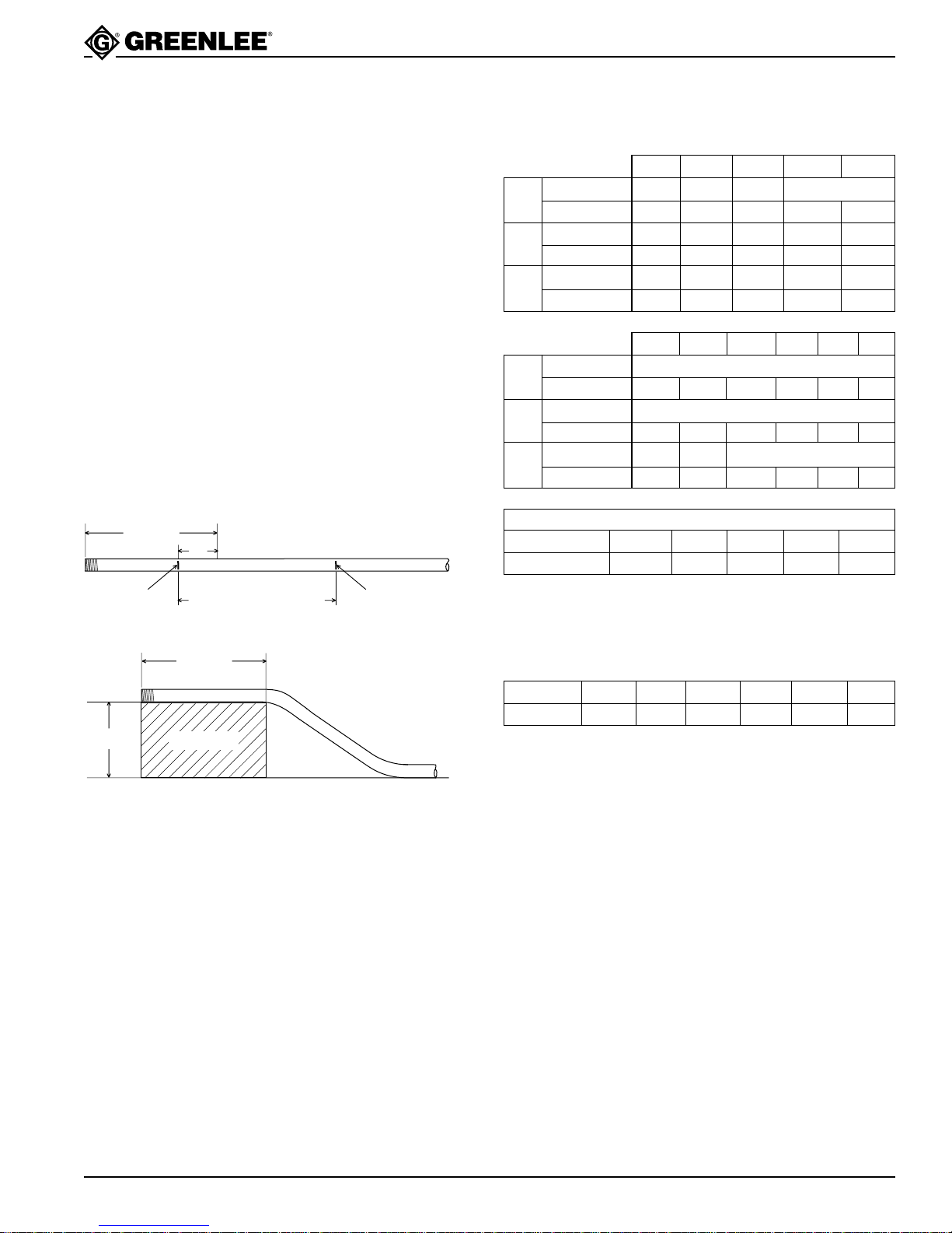
Offsets
1. Measure the height and length of the obstruction.
Select the angle to be used.
2. See the Minimum Offset section of the Offset Table.
The height of the obstruction must be equal to or
greater than the Minimum Offset.
3. Refer to the X Table to find the X dimension. Refer
to the Offset Table to find the Center-To-Center
Distance.
Note: If the center-to-center distance is not
shown, calculate it by using the multipliers
shown in the Offset Table.
4. Mark the conduit as shown.
5. Insert the conduit into the bender. Align Mark 1 with
the front edge of the hook and bend the conduit.
6. Align Mark 2 with the front edge of the hook. With-
out removing the conduit from the bender, rotate the
conduit 180°. Make the second bend.
LENGTH
“X”
MARK 1 MARK 2
CENTER TO CENTER
DISTANCE
Offset Table
OFFSET ➤ 246810
Max Conduit Size 3/4 1-1/2 2 2
15°
Center-to-Center 7-3/4 15-7/16 23-3/16 30-15/16 38-5/8
Max Conduit Size 3/4 1 1-1/2 2
30°
Center-to-Center 8 12 16 20
Max Conduit Size 1/2 1 1-1/4
45°
Center-to-Center 8-1/2 11-5/16 14-1/8
OFFSET ➤ 12 14 16 18 20 22
Max Conduit Size 2
15°
Center-to-Center 46-3/8 54-1/16 61-13/16 69-9/16 77-1/4 85
Max Conduit Size 2
30°
Center-to-Center 24 28 32 36 40 44
Max Conduit Size 1-1/2 2 2
45°
Center-to-Center 16-15/16 19-13/16 22-5/8 25-7/16 28-1/4 31-1/8
CENTER-TO-CENTER DISTANCE = OFFSET HEIGHT x MULTIPLIER
OFFSET ANGLE 10° 15° 22-1/2° 30° 45°
MULTIPLIER 5.8 3.9 2.6 2.0 1.4
Figures are approximate
HEIGHT
LENGTH
OBSTRUCTION
X Table
CONDUIT SIZE 1/2 3/4 1 1-1/4 1-1/2 2
“X” 3-1/16 3-1/16 3-3/16 4 4-1/4 4-1/2
Figures are approximate
Greenlee Textron / Subsidiary of Textron Inc.
19
4455 Boeing Dr., Rockford, IL 61109-2988 815/397-7070
Page 20
555BAT™ Battery-Powered Bender
Additional Bending Instructions
The following drawings and bending tables are intended
to provide the information necessary to accomplish the
most common types of bends. The Bending Tables
contain conduit marking information.
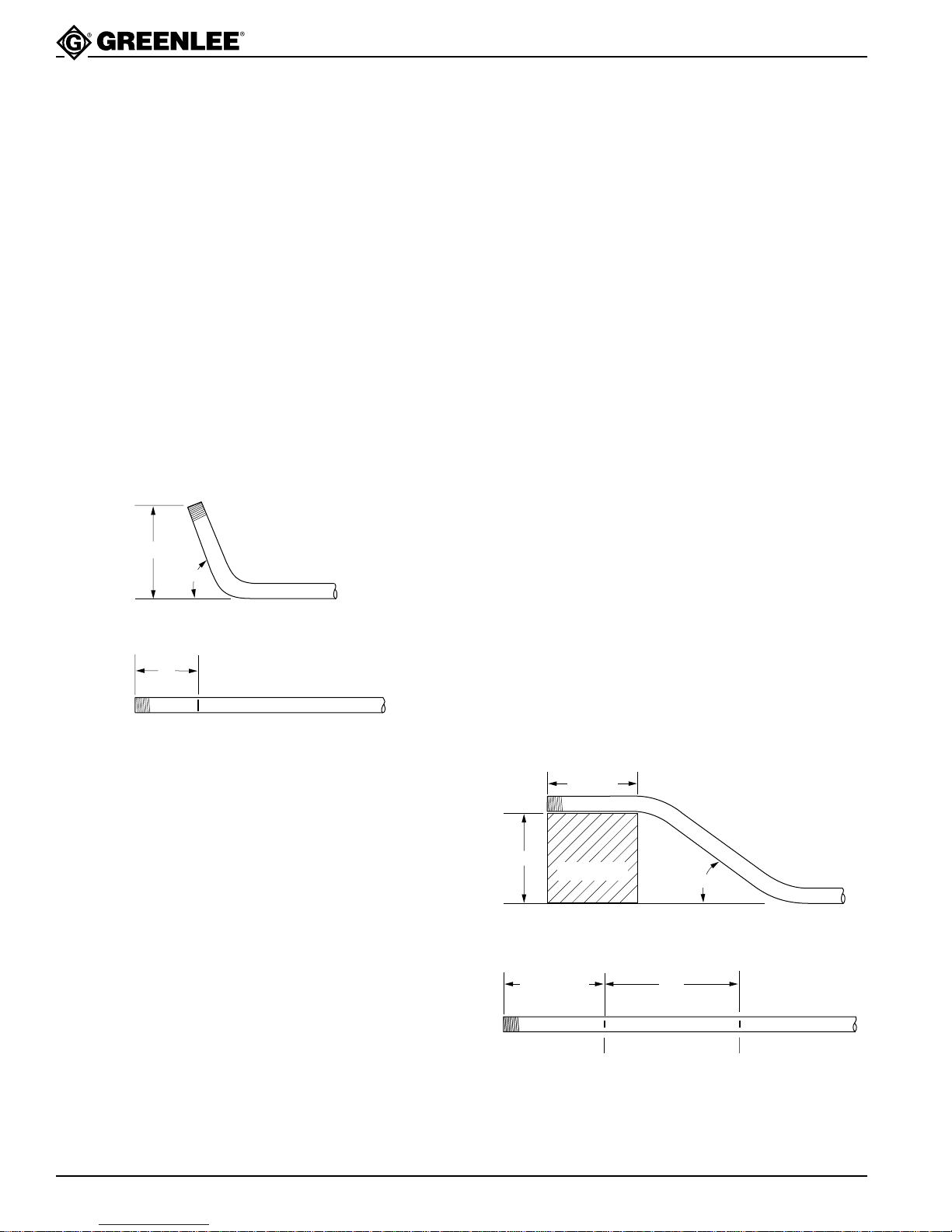
Stubs
1. Select the size and type of conduit. Determine the
height of stub and the angle to be used.
2. Find the table that corresponds to the size and type
of conduit selected in Step 1.
3. Under the column labeled ANGLE, find the appropriate angle.
4. Find the row labeled Y. In the row at the top of the
page, find the height (H) of the stub. The number
shown at the intersection of row Y and column H is
the distance Y. Place the bending mark Y inches
from the end of the conduit.
5. Bend the conduit.
HEIGHT
ANGLE
Y
Offsets
An offset is used to route the conduit around an obstruction. To make an offset, two equal bends are required.
The distance between the two bends is the center-tocenter distance.
When working past an obstruction, it is necessary to
determine the location of the first bend. The center-tocenter distance is then used to determine the location of
the second bend. When working toward an obstruction,
it is necessary to determine the location of the second
bend. The center-to-center distance is then used to
determine the location of the first bend.
Working Past an Obstruction
1. Select the size and type of conduit. Measure the
height of the obstruction and the distance labeled
LENGTH. Determine the angle to be used.
2. Find the table that corresponds to the size and type
of conduit selected in Step 1.
3. To the right of the size and type of conduit, find the
dimension labeled X. Subtract X from LENGTH.
Place the first bending mark this distance from the
end of the conduit.
4. Under the column labeled ANGLE, find the appropriate angle. Find the row labeled L1. In the row at
the top of the page, find the height (H) of the offset.
The number shown at the intersection of row L1 and
column H is L1. Place the second bending mark L1
inches from the first bending mark.
5. Bend the conduit.
MARK
HEIGHT
START OF
FIRST
BEND
LENGTH
OBSTRUCTION
MARK 1 MARK 2
ANGLE
L1LENGTH – X
Greenlee Textron / Subsidiary of Textron Inc.
20
4455 Boeing Dr., Rockford, IL 61109-2988 815/397-7070
Page 21
555BAT™ Battery-Powered Bender
Additional Bending Instructions (cont’d)
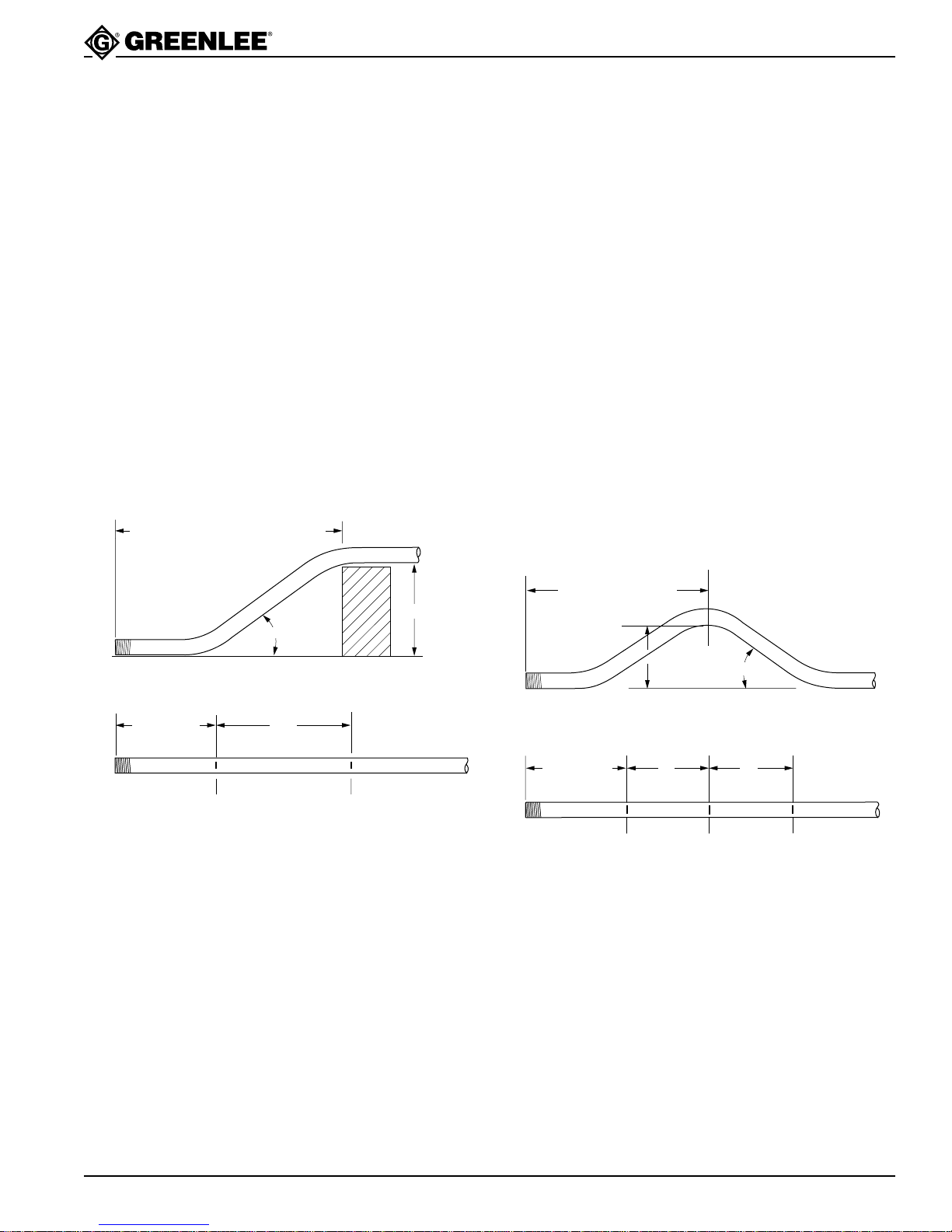
Working Toward an Obstruction
1. Select the size and type of conduit. Measure the
height of the obstruction and the distance labeled
LENGTH TO END OF SECOND BEND. Determine
the angle to be used.
2. Find the table that corresponds to the size and type
of conduit selected in Step 1.
3. Under the column labeled ANGLE, find the appropriate angle. Find the row labeled Z. In the row at
the top of the page, find the height (H) of the offset.
The number shown at the intersection of the Z row
and the H column is Z. Subtract Z from LENGTH
TO THE END OF SECOND BEND. Place the first
bending mark this distance from the end of the
conduit.
4. In the same column, find the row labeled L1. Place
the second bending mark L1 inches from the first
bending mark.
5. Bend the conduit.
LENGTH TO END OF SECOND BEND
Three-Bend Saddle
1. Select the size and type of conduit. Measure the
height of the obstruction and the distance from the
end of the conduit to the center (LENGTH TO
CENTER) of the bend. Determine the angle to be
used.
2. Find the table that corresponds to the size and type
of conduit selected in Step 1.
3. Under the column labeled ANGLE, find the appropriate angle. Find the row labeled Z. In the row at
the top of the page, find the height (H) of the offset.
The number shown at the intersection of the Z row
and the appropriate H column is Z. Subtract Z from
the LENGTH TO CENTER. Place the first bending
mark this distance from the end of the conduit.
4. In the same column, find the row labeled L1. Place
the second bending mark L1 inches from the first
bending mark.
5. In the same column, find the row labeled L2. Place
the third bending mark L2 inches from the second
bending mark.
6. Bend the conduit.
ANGLE
L1LENGTH – Z
MARK 1 MARK 2
HEIGHT
LENGTH TO CENTER
HEIGHT
MARK 1
L1LENGTH – Z
MARK 2
ANGLE
L2
MARK 3
Greenlee Textron / Subsidiary of Textron Inc.
21
4455 Boeing Dr., Rockford, IL 61109-2988 815/397-7070
Page 22
555BAT™ Battery-Powered Bender
Additional Bending Instructions (cont’d)
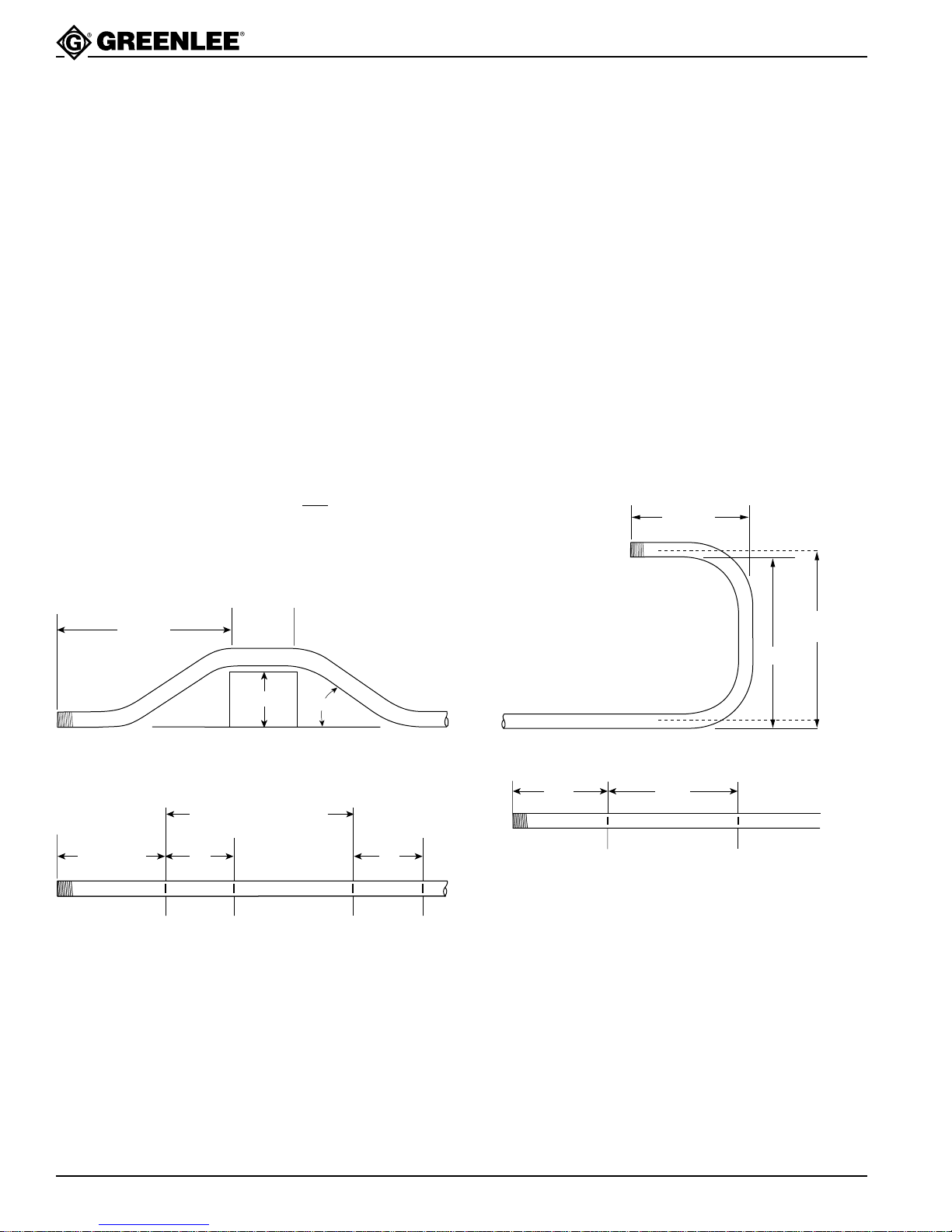
Four-Bend Saddle
1. Select the size and type of conduit. Measure the
height of the obstruction, the distance labeled
LENGTH, and the distance labeled STRAIGHT
SECTION. Determine the angle to be used.
2. Find the table that corresponds to the size and type
of conduit selected in Step 1.
3. Under the column labeled ANGLE, find the appropriate angle. Find the row labeled Z. In the row at
the top of the page, find the height (H) of the offset.
The number shown at the intersection of the Z row
and the appropriate H column is Z. Subtract Z from
the LENGTH. Place the first bending mark this
distance from the end of the conduit.
4. In the same column, find the row labeled L1. Place
the second bending mark L1 inches from the first
bending mark.
5. In the same column, find the row labeled L2. Add L2
to the STRAIGHT SECTION. Place the third bending mark this distance from the
first bending mark.
6. Make the final bending mark L1 inches from the
third bending mark.
7. Bend the conduit.
U-Bends
1. Select the size and type of conduit. Determine the
LENGTH and the HEIGHT.
2. Find the table that corresponds to the size and type
of conduit selected in Step 1.
3. Under the column labeled ANGLE, find 90°.
4. Find the row labeled Y. In the row at the top of the
page, find the height (H) that corresponds to the
LENGTH. The number shown at the intersection of
the Y row and the appropriate H column is the
distance Y. Place the bending mark Y inches from
the end of the conduit.
5. Find the row labeled L1, and go to the right to find
the height (H) that corresponds to the HEIGHT.
6. The number shown at the intersection of the L1 row
and the appropriate H column is L1. Place the
second bending mark L1 inches from the first mark.
7. Bend the conduit.
LENGTH
LENGTH
LENGTH – Z
STRAIGHT
SECTION
HEIGHT
L2 + STRAIGHT SECTION
L1 L1
MARK 1 MARK 2 MARK 3
ANGLE
MARK 4
HEIGHT
@ ???
HEIGHT
Y
MARK 1
L1
MARK 2
Greenlee Textron / Subsidiary of Textron Inc.
22
4455 Boeing Dr., Rockford, IL 61109-2988 815/397-7070
Page 23

555BAT™ Battery-Powered Bender
Additional Bending Tables
DIM ANGLE 2" 4" 6" 8" 10" 12" 15" 18" 24" 36"
1/2 " EMT
Y 15 3.74 11.47 19.20 26.92 34.65 42.38 53.97 65.56 88.74 135.11
L1 15 7.72 15.45 23.18 30.90 38.63 46.36 57.95 69.54 92.72 139.09
L2 15 8.94 16.66 24.39 32.12 39.84 47.57 59.16 70.75 93.94 140.30
MINIMUM H = 0.84
MINIMUM H = 1.48
MINIMUM H = 2.25
MINIMUM H = 4.14
MINIMUM H = 6.38
MINIMUM H = 11.29
Z 15 10.70 18.16 25.62 33.09 40.55 48.02 59.21 70.41 92.80 137.59
Y 22.5 1.37 6.60 11.82 17.05 22.28 27.50 35.34 43.18 58.86 90.22
L1 22.5 5.20 10.43 15.65 20.88 26.11 31.33 39.17 47.01 62.69 94.05
L2 22.5 7.02 12.25 17.48 22.70 27.93 33.16 41.00 48.83 64.51 95.87
Z 22.5 8.68 13.51 18.34 23.17 28.00 32.83 40.07 47.31 61.80 90.77
Y 30 0.04 4.04 8.04 12.04 16.04 20.04 26.04 32.04 44.04 68.04
L1 30 7.94 11.94 15.94 19.94 23.94 29.94 35.94 47.94 71.94
L2 30 10.37 14.37 18.37 22.37 26.37 32.37 38.37 50.37 74.37
Z 30 11.42 14.89 18.35 21.82 25.28 30.48 35.67 46.07 66.85
Y 45 1.23 4.05 6.88 9.71 12.54 16.78 21.02 29.51 46.48
L1 45 8.29 11.11 13.94 16.77 21.01 25.26 33.74 50.71
L2 45 11.93 14.76 17.59 20.42 24.66 28.90 37.39 54.36
Z 45 11.85 13.85 15.85 17.85 20.85 23.85 29.85 41.85
Y 60 1.83 4.14 6.45 8.76 12.22 15.69 22.62 36.47
L1 60 8.74 11.05 13.36 16.82 20.29 27.21 41.07
L2 60 13.60 15.91 18.22 21.68 25.14 32.07 45.93
Z 60 11.99 13.14 14.30 16.03 17.76 21.22 28.15
Y 90 1.00 3.00 5.00 8.00 11.00 17.00 29.00
L1 90 10.01 13.01 16.01 22.01 34.01
L2 90 17.30 20.30 23.30 29.30 41.30
Z 90 11.29 11.29 11.29 11.29 11.29
3/4 " EMT
MINIMUM H = 1.12
MINIMUM H = 1.94
MINIMUM H = 2.92
MINIMUM H = 5.27
MINIMUM H = 8.03
MINIMUM H= 13.95
Y 15 2.35 10.07 17.80 25.53 33.26 40.98 52.58 64.17 87.35 133.71
L1 15 7.72 15.45 23.17 30.90 38.63 46.36 57.95 69.54 92.72 139.08
L2 15 9.17 16.90 24.62 32.35 40.08 47.81 59.40 70.99 94.17 140.54
Z 15 11.79 19.26 26.72 34.19 41.65 49.11 60.31 71.51 93.90 138.68
Y 22.5 0.05 5.28 10.50 15.73 20.95 26.18 34.02 41.86 57.54 88.90
L1 22.5 5.20 10.42 15.65 20.88 26.10 31.33 39.17 47.01 62.69 94.04
L2 22.5 7.37 12.60 17.83 23.05 28.28 33.50 41.34 49.18 64.86 96.22
Z 22.5 9.90 14.73 19.56 24.39 29.22 34.04 41.29 48.53 63.02 91.99
Y 30 2.72 6.72 10.72 14.72 18.72 24.72 30.72 42.72 66.72
L1 30 7.93 11.93 15.93 19.93 23.93 29.93 35.93 47.93 71.93
L2 30 10.83 14.83 18.83 22.83 26.83 32.83 38.83 50.83 74.83
Z 30 12.77 16.23 19.70 23.16 26.62 31.82 37.02 47.41 68.19
Y 45 2.67 5.50 8.33 11.15 15.40 19.64 28.12 45.09
L1 45 8.25 11.08 13.90 16.73 20.97 25.22 33.70 50.67
L2 45 12.60 15.43 18.25 21.08 25.33 29.57 38.05 55.02
Z 45 13.46 15.46 17.46 19.46 22.46 25.46 31.46 43.46
Y 60 0.33 2.64 4.95 7.26 10.72 14.18 21.11 34.97
L1 60 10.95 13.26 16.72 20.19 27.12 40.97
L2 60 16.75 19.06 22.53 25.99 32.92 46.78
Z 60 15.04 16.20 17.93 19.66 23.12 30.05
Y 90 1.13 3.13 6.13 9.13 15.13 27.13
L1 90 12.62 15.62 21.62 33.62
L2 90 21.32 24.32 30.32 42.32
Z 90 13.95 13.95 13.95 13.95
Greenlee Textron / Subsidiary of Textron Inc.
23
4455 Boeing Dr., Rockford, IL 61109-2988 815/397-7070
Page 24

555BAT™ Battery-Powered Bender
Additional Bending Tables (cont’d)
DIM ANGLE 2" 4" 6" 8" 10" 12" 15" 18" 24" 36"
1" EMT
Y 15 1.35 9.07 16.80 24.53 32.26 39.98 51.57 63.16 86.35 132.71
L1 15 7.72 15.44 23.17 30.90 38.63 46.35 57.95 69.54 92.72 139.08
L2 15 9.54 17.26 24.99 32.72 40.45 48.17 59.76 71.36 94.54 140.90
MINIMUM H = 1.31
MINIMUM H = 2.29
MINIMUM H = 3.47
MINIMUM H = 6.35
MINIMUM H = 9.74
MINIMUM H = 17.12
Z 15 12.51 19.98 27.44 34.91 42.37 49.83 61.03 72.23 94.62 139.40
Y 22.5 4.33 9.56 14.78 20.01 25.24 33.07 40.91 56.59 87.95
L1 22.5 10.42 15.64 20.87 26.10 31.32 39.16 47.00 62.68 94.04
L2 22.5 13.15 18.37 23.60 28.82 34.05 41.89 49.73 65.41 96.77
Z 22.5 15.64 20.47 25.30 30.13 34.96 42.20 49.44 63.93 92.90
Y 30 1.75 5.75 9.75 13.75 17.75 23.75 29.75 41.75 65.75
L 30 7.91 11.91 15.91 19.91 23.91 29.91 35.91 47.91 71.91
L2 30 11.55 15.55 19.55 23.55 27.55 33.55 39.55 51.55 75.55
Z 30 13.87 17.34 20.80 24.27 27.73 32.92 28.12 48.51 69.30
Y 45 1.56 4.39 7.22 10.05 14.29 18.53 27.02 43.99
L1 45 11.01 13.84 16.67 20.91 25.16 33.64 50.61
L2 45 16.47 19.30 22.13 26.37 30.62 39.10 56.07
Z 45 16.98 18.98 20.98 23.98 26.98 32.98 44.98
Y 60 1.33 3.64 5.95 9.42 12.88 19.81 33.67
L1 60 10.80 13.11 16.57 20.04 26.97 40.82
L2 60 18.08 20.39 23.85 27.32 34.24 48.10
Z 60 17.02 18.17 19.91 21.64 25.10 32.03
Y 90 1.25 4.25 7.25 13.25 25.25
L1 90 15.02 21.02 33.02
L2 90 25.93 31.93 43.93
Z90 17.12 17.12 17.12
1-1/4" EMT
MINIMUM H = 1.48
MINIMUM H = 2.66
MINIMUM H = 4.09
MINIMUM H = 7.65
MINIMUM H = 11.92
MINIMUM H = 21.38
Y 15 0.26 7.99 15.72 23.45 31.17 38.90 50.49 62.08 85.27 131.63
L1 15 7.71 15.44 23.17 30.90 38.62 46.35 57.94 69.53 92.72 139.08
L2 15 10.07 17.80 25.52 33.25 40.98 48.71 60.30 71.89 95.07 141.44
Z 15 13.20 20.66 28.12 35.59 43.05 50.52 61.71 72.91 95.30 140.09
Y 22.5 3.33 8.55 13.78 19.01 24.23 32.07 39.91 55.59 86.95
L1 22.5 10.41 15.63 20.86 26.09 31.31 39.15 46.99 62.67 94.03
L2 22.5 13.94 19.17 24.40 29.62 34.85 42.69 50.53 66.21 97.56
Z 22.5 16.60 21.43 26.26 31.09 35.91 43.16 50.40 64.89 93.86
Y 30 0.72 4.72 8.72 12.72 16.72 22.72 28.72 40.72 64.72
L1 30 11.89 15.89 19.89 23.89 29.89 35.89 47.89 71.89
L2 30 16.61 20.61 24.61 28.61 34.61 40.61 52.61 76.61
Z 30 18.58 22.04 25.51 28.97 34.17 39.37 49.76 70.54
Y 45 0.33 3.15 5.98 8.81 13.05 17.30 25.78 42.75
L1 45 10.93 13.75 16.58 20.83 25.07 33.55 50.52
L2 45 18.00 20.83 23.66 27.90 32.14 40.63 57.60
Z 45 18.82 20.82 22.82 25.82 28.82 34.82 46.82
Y 60 2.11 4.42 7.89 11.35 18.28 32.14
L1 60 12.89 16.35 19.82 26.74 40.60
L2 60 22.32 25.79 29.25 36.18 50.04
Z 60 20.69 22.42 24.16 27.62 34.55
Y 90 1.88 4.88 10.88 22.88
L1 90 20.13 32.13
L2 90 34.29 46.29
Z90 21.38 21.38
Greenlee Textron / Subsidiary of Textron Inc.
24
4455 Boeing Dr., Rockford, IL 61109-2988 815/397-7070
Page 25

555BAT™ Battery-Powered Bender
Additional Bending Tables (cont’d)
DIM ANGLE 2" 4" 6" 8" 10" 12" 15" 18" 24" 36"
SIZE = 1-1/2" EMT
Y 15 6.26 13.99 21.72 29.44 37.17 48.76 60.35 83.53 129.90
L1 15 7.71 15.44 23.17 30.90 38.62 46.35 57.94 69.53 92.72 139.08
L2 15 9.95 17.68 25.40 33.13 40.86 48.58 60.18 71.77 94.95 141.31
MINIMUM H = 1.81
MINIMUM H = 3.11
MINIMUM H = 4.64
MINIMUM H = 8.33
MINIMUM H = 12.61
MINIMUM H = 21.77
Z 15 14.42 21.88 29.35 36.81 44.28 51.74 62.94 74.13 96.53 141.31
Y 22.5 1.77 7.00 12.22 17.45 22.68 30.52 38.36 54.03 85.39
L1 22.5 10.41 15.64 20.86 26.09 31.31 39.15 46.99 62.67 94.03
L2 22.5 13.76 18.98 24.21 29.44 34.66 42.50 50.34 66.02 97.38
Z 22.5 17.76 22.59 27.42 32.25 37.07 44.32 51.56 66.04 95.02
Y 30 3.26 7.26 11.26 15.26 21.26 27.2639.2663.26
L1 30 11.90 15.90 19.90 23.90 29.90 35.90 47.90 71.90
L2 30 16.36 20.36 24.36 28.36 34.36 40.36 52.36 76.36
Z 30 19.67 23.14 26.60 30.07 35.26 40.46 50.85 71.64
Y 45 1.84 4.67 7.50 11.74 15.98 24.47 41.44
L1 45 13.78 16.60 20.85 25.09 33.57 50.54
L2 45 20.47 23.30 27.55 31.79 40.27 57.24
Z 45 21.78 23.78 26.78 29.78 35.78 47.78
Y 60 0.91 3.22 6.68 10.15 17.07 30.93
L1 60 16.40 19.87 26.80 40.65
L2 60 25.34 28.80 35.73 49.58
Z 60 23.22 24.95 28.42 35.34
Y 90 0.89 3.89 9.89 21.89
L1 90 20.34 32.34
L2 90 33.74 45.74
Z90 21.77 21.77
2" EMT
MINIMUM H = 1.89
MINIMUM H = 3.28
MINIMUM H = 4.94
MINIMUM H = 8.95
MINIMUM H = 13.63
MINIMUM H = 23.74
Y 15 5.15 12.87 20.60 28.33 36.05 47.65 59.24 82.42 128.78
L1 15 7.71 15.44 23.17 30.90 38.62 46.35 57.94 69.53 92.71 139.08
L2 15 10.19 17.92 25.64 33.37 41.10 48.83 60.42 72.01 95.19 141.56
Z 15 14.77 22.24 29.70 37.17 44.63 52.10 63.29 74.49 96.88 141.66
Y 22.5 0.88 6.11 11.33 16.56 21.79 29.62 37.46 53.14 84.50
L1 22.5 10.40 15.63 20.86 26.08 31.31 39.15 46.99 62.67 94.02
L2 22.5 14.12 19.35 24.57 29.80 35.02 42.86 50.70 66.38 97.74
Z 22.5 18.24 23.07 27.90 32.73 37.55 44.80 52.04 66.52 95.50
Y 30 2.45 6.45 10.45 14.45 20.45 26.45 38.45 62.45
L1 30 11.88 15.88 19.88 23.88 29.88 35.88 47.88 71.88
L2 30 16.84 20.84 24.84 28.84 34.84 40.84 52.84 76.84
Z 30 20.28 23.75 27.21 30.67 35.87 41.07 51.46 72.24
Y 45 1.02 3.85 6.68 10.92 15.16 23.65 40.62
L1 45 13.74 16.56 20.81 25.05 33.53 50.50
L2 45 21.16 23.99 28.24 32.48 40.96 57.93
Z 45 22.66 24.66 27.66 30.66 36.66 48.66
Y 60 0.00 2.31 5.77 9.23 16.16 30.02
L1 60 16.30 19.77 26.70 40.55
L2 60 26.21 29.67 36.60 50.46
Z 60 24.40 26.14 29.60 36.53
Y90 2.62 8.62 20.62
L1 90 19.94 31.94
L2 90 34.80 46.80
Z90 23.74 23.74
Greenlee Textron / Subsidiary of Textron Inc.
25
4455 Boeing Dr., Rockford, IL 61109-2988 815/397-7070
Page 26

555BAT™ Battery-Powered Bender
Additional Bending Tables (cont’d)
DIM ANGLE 2" 4" 6" 8" 10" 12" 15" 18" 24" 36"
1/2" IMC, Rigid, & 40 Mil PVC Coated Rigid
Y 15 3.03 10.76 18.48 26.21 33.94 41.67 53.26 64.85 88.03 134.39
L1 15 7.72 15.45 23.18 30.90 38.63 46.36 57.95 69.54 92.72 139.09
L2 15 8.87 16.59 24.32 32.05 39.78 47.50 59.10 70.69 93.87 140.23
MINIMUM H = 0.95
MINIMUM H = 1.62
MINIMUM H = 2.42
MINIMUM H = 4.33
MINIMUM H = 6.55
MINIMUM H = 11.26
Z 15 11.12 18.58 26.05 33.51 40.97 48.44 59.63 70.83 93.22 138.01
Y 22.5 .77 5.98 11.21 16.44 21.66 26.89 34.73 42.57 58.25 89.60
L1 22.5 5.20 10.43 15.66 20.88 26.11 31.34 39.17 47.01 62.69 94.05
L2 22.5 6.92 12.15 17.38 22.60 27.83 33.06 40.89 48.73 64.41 95.77
Z 22.5 9.07 13.90 18.73 23.56 28.38 33.21 40.46 47.70 62.18 91.15
Y 30 3.49 7.49 11.49 15.49 19.49 25.49 31.49 43.49 67.49
L1 30 7.95 11.95 15.95 19.95 23.95 29.95 35.95 47.95 71.95
L2 30 10.24 14.24 18.24 22.24 26.24 32.24 38.24 50.24 74.24
Z 30 11.78 15.24 18.70 22.17 25.63 30.83 36.02 46.42 67.20
Y 45 3.59 6.41 9.23 12.06 16.30 20.55 29.03 46.00
L1 45 8.30 11.13 13.95 16.78 21.02 25.27 33.75 50.72
L2 45 11.74 14.57 17.39 20.22 24.46 28.71 37.19 54.16
Z 45 12.13 14.13 16.13 18.13 21.13 24.13 30.13 42.13
Y 60 1.42 3.73 6.04 8.34 11.81 15.27 22.20 36.06
L1 60 8.77 11.08 13.39 16.85 20.31 27.24 41.10
L2 60 13.35 15.66 17.97 21.44 24.90 31.83 45.69
Z 60 12.18 13.33 14.49 16.22 17.95 21.41 28.34
Y 90 .71 2.71 4.71 7.71 10.71 16.70 28.70
L1 90 10.12 13.12 16.12 22.12 34.12
L2 90 17.00 20.00 23.00 29.00 41.00
Z 90 11.26 11.26 11.26 11.26 11.26
3/4" IMC, Rigid, & 40 Mil PVC Coated Rigid
Y 15 1.86 9.58 17.31 25.04 32.77 40.49 52.08 63.68 86.86 133.22
L1 15 7.72 15.45 23.17 30.90 38.63 46.36 57.95 69.54 92.72 139.08
L2 15 9.19 16.91 24.64 32.37 40.09 47.82 59.41 71.00 94.19 140.55
MINIMUM H = 1.19
MINIMUM H = 2.05
MINIMUM H = 3.06
MINIMUM H = 5.49
MINIMUM H = 8.31
MINIMUM H = 14.33
Z 15 12.06 19.53 26.89 34.46 41.92 49.38 60.58 71.78 94.17 138.95
Y 22.5 4.85 10.08 15.31 20.53 25.76 33.60 41.44 57.12 88.47
L1 22.5 10.42 15.65 20.88 26.10 31.33 39.17 47.01 62.69 94.04
L2 22.5 12.62 17.85 23.08 28.30 33.53 41.37 49.21 64.89 96.24
Z 22.5 15.01 19.84 24.67 29.49 34.32 41.57 48.81 63.29 92.26
Y 30 2.33 6.33 10.33 14.33 18.33 24.33 30.33 42.33 66.33
L1 30 7.93 11.93 15.93 19.93 23.93 29.93 35.93 47.93 71.93
L2 30 10.86 14.86 18.86 22.86 26.86 32.86 38.86 50.86 74.86
Z 30 13.05 16.52 19.98 23.45 26.91 32.11 37.30 47.70 68.48
Y 45 2.31 5.13 7.96 10.79 15.03 19.28 27.76 44.73
L1 45 8.24 11.07 13.90 16.73 20.97 25.21 33.70 50.67
L2 45 12.64 15.47 18.30 21.13 25.37 29.61 38.10 55.07
Z 45 13.76 15.76 17.76 19.76 22.76 25.76 31.76 43.76
Y 60 2.28 4.59 6.90 10.36 13.83 20.75 34.61
L1 60 10.94 13.25 16.72 20.18 27.11 40.97
L2 60 16.81 19.12 22.58 26.05 32.98 46.83
Z 60 15.36 16.52 18.25 19.88 23.45 30.38
Y 90 .76 2.76 5.76 8.76 14.76 26.76
L1 90 12.60 15.60 21.60 33.60
L2 90 21.39 24.39 30.39 42.39
Z 90 14.33 14.33 14.33 14.33
Greenlee Textron / Subsidiary of Textron Inc.
26
4455 Boeing Dr., Rockford, IL 61109-2988 815/397-7070
Page 27

555BAT™ Battery-Powered Bender
Additional Bending Tables (cont’d)
DIM ANGLE 2" 4" 6" 8" 10" 12" 15" 18" 24" 36"
1" IMC, Rigid, & 40 Mil PVC Coated Rigid
Y 15 1.08 8.81 16.52 24.25 31.97 39.70 51.29 62.88 86.07 132.43
L1 15 7.72 15.44 23.17 30.90 38.63 46.35 57.94 69.54 92.72 139.08
L2 15 9.59 17.32 25.04 32.77 40.50 48.23 59.82 71.41 94.59 140.95
MINIMUM H = 1.31
MINIMUM H = 2.31
MINIMUM H = 3.51
MINIMUM H = 6.44
MINIMUM H = 9.91
MINIMUM H = 17.49
Z 15 12.53 20.00 27.46 34.93 42.39 49.86 61.05 72.25 94.64 139.43
Y 22.5 4.13 9.35 14.58 19.81 25.03 32.87 40.71 56.39 87.75
L1 22.5 10.42 15.64 20.87 26.09 31.32 39.16 47.00 62.68 94.04
L2 22.5 13.22 18.45 23.68 28.90 34.13 41.97 49.81 65.49 96.84
Z 22.5 15.69 20.52 25.35 30.18 35.01 42.25 49.49 63.98 92.95
Y 30 1.58 5.58 9.58 13.58 17.58 23.58 29.58 41.58 65.58
L1 30 7.91 11.91 15.91 19.91 23.91 29.91 35.91 47.91 71.91
L2 30 11.66 15.66 19.66 23.66 27.66 33.66 39.66 51.66 75.66
Z 30 13.95 17.41 20.88 24.34 27.81 33.00 38.20 48.59 69.38
Y 45 1.42 4.24 7.06 9.89 14.14 18.38 26.86 43.83
L1 45 11.01 13.83 16.66 20.91 25.15 33.63 50.60
L2 45 16.62 19.45 22.28 26.52 30.76 39.25 56.22
Z 45 17.11 19.11 21.11 24.11 27.11 33.11 45.11
Y 60 1.17 3.48 5.79 9.25 12.71 19.64 33.49
L1 60 10.78 13.09 16.55 20.02 26.94 40.80
L2 60 18.27 20.58 24.04 27.50 34.43 48.29
Z 60 17.22 18.37 20.11 21.84 25.30 32.23
Y 90 1.01 4.01 7.01 13.01 25.01
L1 90 14.93 20.93 32.93
L2 90 26.16 32.16 44.16
Z90 17.49 17.49 17.49
1-1/4" IMC, Rigid, & 40 Mil PVC Coated Rigid
Y 15 7.15 14.87 22.60 30.33 38.06 49.65 61.24 84.42 130.78
L1 15 7.71 15.44 23.17 30.90 38.62 46.35 57.94 69.53 92.72 139.08
L2 15 10.07 17.80 25.53 33.25 40.98 48.71 60.30 71.89 95.07 141.44
MINIMUM H = 1.63
MINIMUM H = 2.88
MINIMUM H = 4.38
MINIMUM H = 8.06
MINIMUM H = 11.32
MINIMUM H = 21.96
Z 15 13.77 21.24 28.70 36.17 43.63 51.09 62.29 73.49 95.88 140.66
Y 22.5 2.57 7.80 13.02 18.25 23.47 31.31 39.15 54.83 86.19
L1 22.5 10.41 15.63 20.86 26.09 31.31 39.15 46.99 62.67 94.03
L2 22.5 13.94 19.17 24.40 29.62 34.85 42.69 50.53 66.21 97.56
Z 22.5 17.18 22.01 26.84 31.66 36.49 43.73 50.98 65.46 94.43
Y 30 4.00 8.00 12.00 16.00 22.00 28.00 40.00 64.00
L1 30 11.89 15.89 19.89 23.89 29.89 35.89 47.89 71.89
L2 30 16.61 20.61 24.61 28.61 34.61 40.61 52.61 76.61
Z 30 19.16 22.62 26.09 29.55 34.75 39.94 50.33 71.12
Y 45 2.48 5.31 8.14 12.38 16.62 25.11 42.08
L1 45 13.75 16.58 20.83 25.07 33.55 50.52
L2 45 20.83 23.66 27.90 32.14 40.63 57.60
Z 45 21.40 23.40 26.40 29.40 35.40 47.40
Y 60 1.46 3.77 7.23 10.69 17.62 31.48
L1 60 16.35 19.82 26.74 40.60
L2 60 25.79 29.25 36.18 50.04
Z 60 23.00 24.73 28.20 35.13
Y 90 1.23 4.23 10.23 22.23
L1 90 20.13 32.13
L2 90 34.29 46.29
Z90 21.96 21.96
Greenlee Textron / Subsidiary of Textron Inc.
27
4455 Boeing Dr., Rockford, IL 61109-2988 815/397-7070
Page 28

555BAT™ Battery-Powered Bender
Additional Bending Tables (cont’d)
DIM ANGLE 2" 4" 6" 8" 10" 12" 15" 18" 24" 36"
1-1/2" Rigid & 40 Mil PVC Coated Rigid
Y 15 5.87 13.59 21.32 29.05 36.77 48.37 59.96 83.14 129.50
L1 15 7.71 15.44 23.17 20.90 38.62 46.35 57.94 69.53 92.72 139.08
L2 15 9.94 17.67 25.39 33.12 40.85 48.58 60.17 71.76 94.94 141.31
MINIMUM H = 1.82
MINIMUM H = 3.13
MINIMUM H= 4.68
MINIMUM H= 8.37
MINIMUM H= 12.66
MINIMUM H= 21.80
Z 15 14.50 21.97 29.43 36.89 44.36 51.82 63.02 74.21 96.61 141.39
Y 22.5 1.48 6.71 11.93 17.16 22.38 30.22 38.06 53.74 85.10
L1 22.5 10.41 15.64 20.86 26.09 31.31 39.15 46.99 62.67 94.03
L2 22.5 13.75 18.97 24.20 29.43 34.65 42.49 50.33 66.01 97.37
Z 22.5 17.84 22.67 27.50 32.32 37.15 44.39 51.64 66.12 95.09
Y 30 3.02 7.02 11.02 15.02 21.02 27.02 39.02 63.02
L1 30 11.90 15.90 19.90 23.90 29.90 35.90 47.90 71.90
L2 30 16.35 20.35 24.35 28.35 34.35 40.35 52.35 76.35
Z 30 19.75 23.21 26.68 30.14 35.34 40.53 50.92 71.71
Y 45 1.65 4.48 7.31 11.55 15.79 24.28 41.25
L1 45 13.78 16.60 20.85 25.09 33.58 50.55
L2 45 20.45 23.28 27.52 31.77 40.25 57.22
Z 45 21.84 23.84 26.84 29.84 35.84 47.84
Y 60 0.74 3.05 6.52 9.98 16.91 30.76
L1 60 16.41 19.87 26.80 40.66
L2 60 25.31 28.77 35.70 49.56
Z 60 23.28 25.01 28.47 35.40
Y 90 0.75 3.75 9.75 21.75
L1 90 20.35 32.35
L2 90 33.70 45.70
Z90 21.80 21.80
2" Rigid & 40 Mil PVC Coated Rigid
Y 15 4.42 12.15 19.87 27.60 35.33 46.92 58.51 81.69 128.06
L1 15 7.71 15.44 23.17 30.89 38.62 46.35 57.94 69.53 92.71 139.08
L2 15 10.27 18.00 25.73 33.46 41.18 48.91 60.50 72.09 95.27 141.64
MINIMUM H = 2.00
MINIMUM H = 3.47
MINIMUM H = 5.20
MINIMUM H = 9.38
MINIMUM H = 14.25
MINIMUM H = 24.72
Z 15 15.20 22.66 30.13 37.59 45.06 52.52 63.72 74.91 97.30 142.09
Y 22.5 0.24 5.47 10.70 15.92 21.15 28.99 36.83 52.51 83.86
L1 22.5 10.40 15.63 20.85 26.08 31.31 39.15 46.99 62.66 94.02
L2 22.5 14.24 19.47 24.70 29.92 35.15 42.99 50.83 66.51 97.86
Z 22.5 18.71 23.54 28.36 33.19 38.02 45.26 52.51 66.99 95.96
Y 30 1.84 5.84 9.84 13.84 19.84 25.84 37.84 61.84
L1 30 11.88 15.88 19.88 23.88 29.88 35.88 47.88 71.88
L2 30 17.00 21.00 25.00 29.00 35.00 41.00 53.00 77.00
Z 30 20.79 24.26 27.72 31.19 36.38 41.58 51.97 71.75
Y 45 0.42 3.25 6.08 10.32 14.57 23.05 40.02
L1 45 13.72 16.55 20.79 25.04 33.52 50.49
L2 45 21.40 24.23 28.47 32.72 41.20 58.17
Z 45 23.26 25.26 28.26 31.26 37.26 49.26
Y 60 1.68 5.14 8.61 15.54 29.39
L1 60 16.27 19.73 26.66 40.52
L2 60 26.51 29.97 36.90 50.76
Z 60 25.11 26.85 30.31 37.24
Y90 1.87 7.87 19.87
L1 90 31.80
L2 90 47.16
Z90 24.72
Greenlee Textron / Subsidiary of Textron Inc.
28
4455 Boeing Dr., Rockford, IL 61109-2988 815/397-7070
Page 29

555BAT™ Battery-Powered Bender
Additional Bending Tables (cont’d)
DIM ANGLE 2" 4" 6" 8" 10" 12" 15" 18" 24" 36"
1-1/2" IMC
Y 15 6.41 14.14 21.87 29.60 37.32 48.91 60.51 83.69 130.05
L1 15 7.71 15.44 23.17 30.90 38.62 46.35 57.94 69.53 92.72 139.00
L2 15 9.95 17.68 25.40 33.13 40.86 48.58 60.18 71.77 94.94 141.31
MINIMUM H = 1.69
MINIMUM H = 2.94
MINIMUM H= 4.43
MINIMUM H= 8.02
MINIMUM H= 12.24
MINIMUM H= 21.34
Z 15 13.99 21.45 28.92 36.38 43.85 51.31 62.51 73.70 96.10 140.88
Y 22.5 2.02 7.24 12.47 17.69 22.92 30.76 38.60 54.28 85.64
L1 22.5 10.41 15.64 20.86 26.09 31.31 39.15 46.99 62.67 94.03
L2 22.5 13.76 18.98 24.21 29.44 34.66 42.50 50.34 66.02 97.38
Z 22.5 17.33 22.16 26.99 31.82 36.64 43.89 51.13 65.61 94.59
Y 30 3.55 7.55 11.55 15.55 21.55 27.55 39.55 63.55
L1 30 11.90 15.90 19.90 23.90 29.90 35.90 47.90 71.90
L2 30 16.36 20.36 24.36 28.36 34.36 40.36 52.36 76.36
Z 30 19.24 22.71 26.17 29.64 34.83 40.03 50.42 71.21
Y 45 2.17 5.00 7.83 12.07 16.31 24.80 41.77
L1 45 13.78 16.60 20.85 25.09 33.57 50.54
L2 45 20.47 23.30 27.55 31.79 40.27 57.24
Z 45 21.35 23.35 26.35 29.35 35.35 47.35
Y 60 1.26 3.56 7.03 10.49 17.42 31.28
L1 60 16.40 19.87 26.80 40.65
L2 60 25.34 28.80 35.73 49.58
Z 60 22.79 24.52 27.99 34.91
Y 90 1.25 4.25 10.25 22.25
L1 90 20.34 32.34
L2 90 33.74 45.74
Z90 21.34 21.34
2" IMC
MINIMUM H = 1.84
MINIMUM H = 3.20
MINIMUM H = 4.84
MINIMUM H = 8.80
MINIMUM H = 13.45
MINIMUM H = 23.53
Y 15 5.04 12.77 20.50 28.22 35.95 47.54 59.13 82.31 128.68
L1 15 7.71 15.44 23.17 30.90 38.62 46.35 57.94 69.53 92.71 139.00
L2 15 10.19 17.92 25.64 33.37 41.10 48.83 60.42 72.01 95.19 141.56
Z 15 14.56 22.03 29.49 36.96 44.42 51.89 63.00 74.28 96.67 141.45
Y 22.5 0.88 6.10 11.33 16.56 21.78 29.62 37.46 53.14 84.50
L1 22.5 10.40 15.63 20.86 26.08 31.31 39.15 46.99 62.67 94.02
L2 22.5 14.12 19.35 24.57 29.80 35.02 42.86 50.70 66.38 97.74
Z 22.5 18.03 22.86 27.69 32.52 37.34 44.59 51.83 66.31 95.29
Y 30 2.50 6.50 10.50 14.50 20.50 26.50 38.50 62.50
L1 30 11.88 15.88 19.88 23.88 29.88 35.88 47.88 71.88
L2 30 16.84 20.84 24.84 28.84 34.84 40.84 52.84 76.84
Z 30 20.07 23.54 27.00 30.46 35.66 40.86 51.25 72.03
Y 45 1.12 3.94 6.77 11.02 15.26 23.74 40.71
L1 45 13.74 16.56 20.81 25.05 33.53 50.50
L2 45 21.16 23.99 28.24 32.48 40.96 57.93
Z 45 22.45 24.45 27.45 30.45 36.45 48.45
Y 60 0.11 2.42 5.89 9.35 16.28 20.13
L1 60 16.30 19.77 26.70 20.55
L2 60 26.21 29.67 36.60 50.46
Z 60 24.19 25.93 29.39 26.32
Y90 2.75 8.75 20.75
L1 90 19.94 31.94
L2 90 34.80 46.80
Z90 23.53 23.53
Greenlee Textron / Subsidiary of Textron Inc.
29
4455 Boeing Dr., Rockford, IL 61109-2988 815/397-7070
Page 30
555BAT™ Battery-Powered Bender
Maintenance
Before servicing: turn bender OFF,
disconnect the charger from the
power source and disconnect
battery cables.
Failure to observe this warning can
result in severe injury or death.
Wear eye protection when operating
the bender. Failure to wear eye
protection can result in serious eye
injury from flying debris.
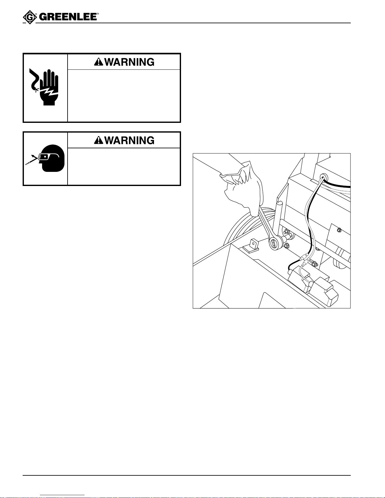
Chain Tension Adjustment
Lubricate the chain and adjust the tension every 6
months.
7. Insert a 1/2" square drive into the eccentric cam (8),
as shown.
Note: The eccentric cam has two mounting
holes for different adjustment positions.
If necessary, remove the mounting bolt and
insert it into the other mounting hole of the
eccentric cam.
8. Torque the eccentric cam to 15 foot-pounds
(20 Newton-meters). Maintain this amount of torque
while tightening the reductor mounting bolts to
35 foot-pounds (47 Newton-meters).
Adjusting Chain Tension
1. Disconnect the battery charger from the power
source.
2. Turn off the bender and disconnect batteries.
3. See the Exploded View. Remove the front cover
(19) and the rear upper guard (63).
4. Loosen the mounting bolts (59) that secure the
reductor (58).
5. Remove the four screws (11) that secure the
countershaft eccentric (9).
6. Rotate the countershaft eccentric to take up
the slack.
Note: If the eccentric is difficult to rotate, tap
it with a hammer and punch to loosen it.
7. Align the holes in the countershaft eccentric with
one of the two sets of holes in the bender chassis.
Replace the screws.
Tip the bender over onto its back to expose the
bottom of the reductor.
9. Connect the batteries. Press BEND or UNLOAD
while spraying a motorcycle chain lubricant on the
inside of the chain between the sprockets. Lubricate
the entire length of the chain. Disconnect the
batteries.
10. Replace the cover and guard.
Replacing the Fuse
1. Disconnect the battery charger from the power
source.
2. Grasp both ends of the fuse holder and pull it apart.
Note: Do not pull on the wires.
3. Remove the defective fuse.
4. Replace with a new fuse.
5. Align the two parts of the fuse holder over the fuse
and push them together. See the Parts List for
proper fuse type.
Greenlee Textron / Subsidiary of Textron Inc.
30
4455 Boeing Dr., Rockford, IL 61109-2988 815/397-7070
Page 31
Maintenance (cont’d)
555BAT™ Battery-Powered Bender
Replacing the Batteries
As batteries age, the recharge time increases and the
discharge time decreases. Replace them when they
are no longer useful.
For assistance in finding the PowerSonic distributor
nearest you, in the United States call 1-800-554-2243,
ext. 3017. Outside of the United States call
1-414-703-5800, ext. 3017.
1. Remove the pins from the bender. Tilt the top of the
bender back to expose the battery compartment.
2. Remove the battery mounting bracket.
3. Disconnect all of the battery cables. Remove the
batteries.
4. Dispose of the batteries in accordance with local,
state, and federal laws. For the location of the
closest recycling center, in North America call the
RBRC (Rechargeable Battery Recycling Corporation)
at 1-800-8-BATTERY. Provide a copy of the battery
MSDS (Material Safety Data Sheet, supplied with
the 555BAT™) for the battery recycler.
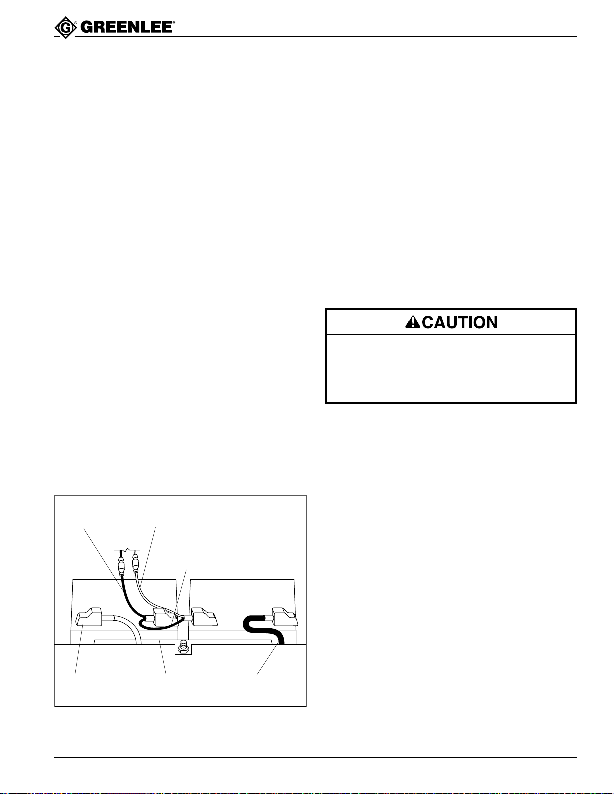
5. Connect the battery cables and cover the battery
terminals with the protective boots, as shown.
Note: Connect the black battery charger cable
to the negative post of Battery 1. Run the
red battery charger cable through the
protective boot and connect it to the positive
post of Battery 2.
6. Install the battery mounting bracket. Tighten the nut
until it is snug – do not overtighten.
7. Tilt the top of the bender to the vertical position.
Replace the two pins.
Electrical Control Unit
1. Disconnect the charger from the power source.
2. Turn off the bender and disconnect batteries.
3. See the Exploded View. Remove
the top cover (45).
4. See the Wiring Layout—General.
Unplug the pendant cord (51) from the Electronic
Control Unit (40).
5. Remove the mounting screws (11).
6. Remove the Electrical Control Unit from the bender.
7. Disconnect the motor leads from the Electronic
Control Unit.
8. Disconnect the red (86) and black (87) wires.
Reductor Gearbox
Benzene, carbon-tetrachloride, acetone and other
similar chemicals can damage the rubber gearbox
seals. Use kerosene for flushing the gearbox and
internal parts. Failure to observe this precaution can
result in damage to the seals and gearbox.
The gearbox does not require periodic maintenance. If
the gearbox is opened, flush all of the lubricant from the
box and internal parts with kerosene. Fill the box with 26
fluid ounces of Mobil 634 synthetic oil.
Replacing the Batteries
BLACK Battery
Charger Cable
RED Battery
Charger Cable
Short BLACK Cable
with Protective Boot
BATTERY 1 BATTERY 2
RED Battery Cable
with Protective Boot
Greenlee Textron / Subsidiary of Textron Inc.
Battery
Mounting Bracket
BLACK
Battery Cable
31
4455 Boeing Dr., Rockford, IL 61109-2988 815/397-7070
Page 32

Troubleshooting
555BAT™ Battery-Powered Bender
PROBLEM SUGGESTED REMEDY
Bender will not operate Power switch is OFF. Turn power ON.
Battery voltage is low. Charge the batteries.
Battery connections are loose. Tighten the battery connections.
Bender operates slowly. Battery voltage is low. Charge the batteries.
Motor “hums”; shoe does Battery voltage is low. Charge the batteries.
not rotate.
Batteries will not charge. Battery connections are loose. Tighten the battery connections.
Battery connectors are corroded or dirty.
Charger’s in-line fuses are blown. Replace charger’s fuses.
Charger is faulty. Test charger’s output with voltmeter.
PROBABLE CAUSE
Clean battery connectors.
Replace charger if output is less
than 12 volts.
Batteries are faulty. Replace batteries.
Low battery life. Batteries are exhausted. Replace batteries.
Bender overbends conduit Too much squeeze on Decrease squeeze. See instructions
slightly. 1-1/2" – 2" EMT or IMC. under Adjusting the squeeze.
Conduit has unusual characteristics. Bend to a smaller angle to
compensate.
Bender underbends conduit Too little squeeze on Increase squeeze. See instructions
slightly. 1-1/2" – 2" EMT or IMC. under Adjusting the squeeze.
Conduit has unusual characteristics.
Bend to a larger angle to compensate.
Greenlee Textron / Subsidiary of Textron Inc.
32
4455 Boeing Dr., Rockford, IL 61109-2988 815/397-7070
Page 33
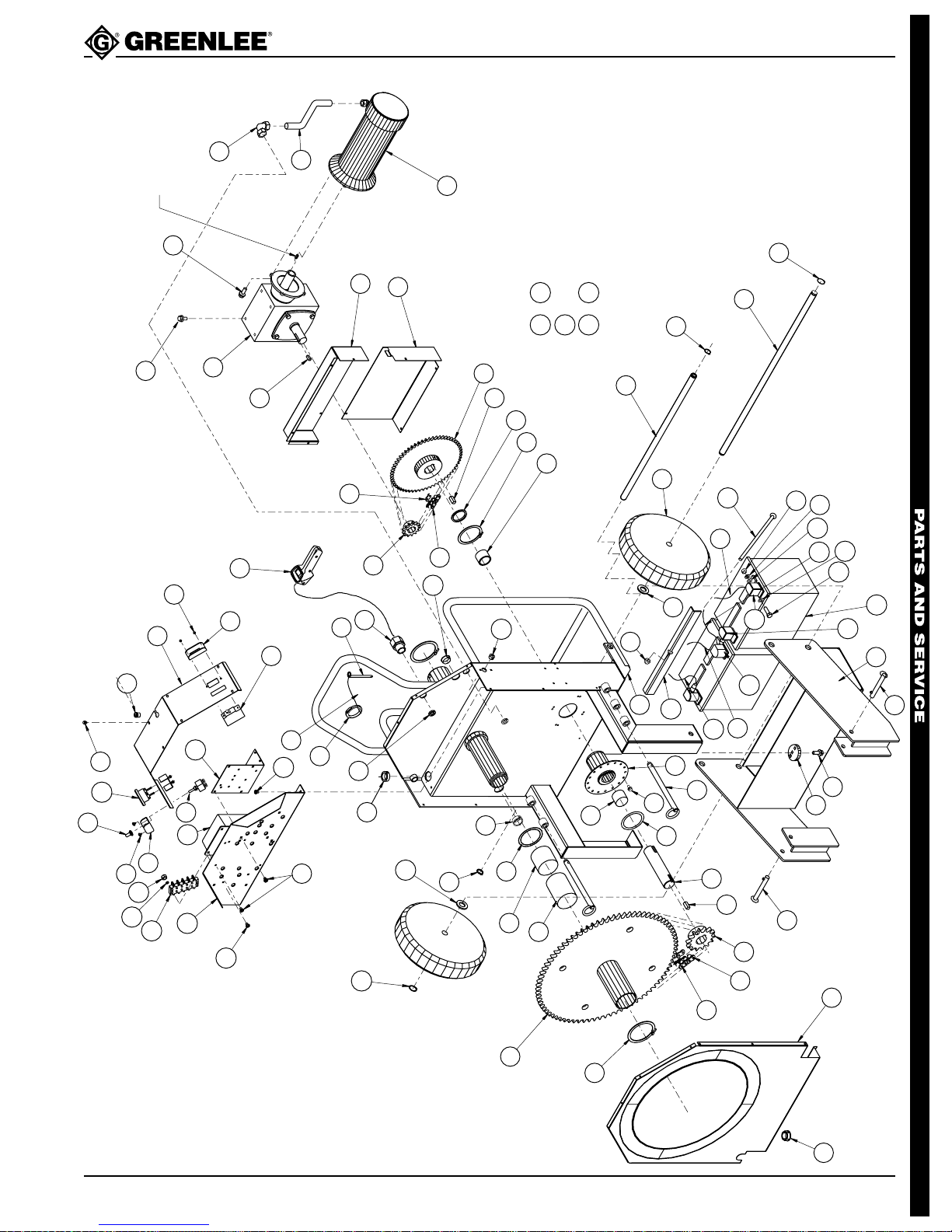
Exploded View
35
34
31
33
38
11
11
37
39
32
42
52
77
74
78
80
9
20
20
20
26
68
49
30
29
45
19
63
64
26
69
60
61
62
7
59
54
55
58
57
56
17
18
15
65
12
66
13
13
21
23
22
25
50
28
NOTE:
KEY SUPPLIED
WITH ITEM
#25 (MOTOR)
11
10
12
14
7
8
6
15
16
5
5
67
41
48
47
46
44
26
27
24
2
3
36
71
79
70
43
51
4
76
26
27
1
72
73
75
73
53
40
16 & 65 : Torque set screw to 150/200 inch-pounds
56 : Torque set screw to 15/20 inch-pounds
14 & 15 : Apply “Loctite CVV” (key fit) to keyway
in shaft before assembling key
90
555BAT™ Battery-Powered Bender
Greenlee Textron / Subsidiary of Textron Inc.
33
4455 Boeing Dr., Rockford, IL 61109-2988 815/397-7070
Page 34
Greenlee Textron / Subsidiary of Textron Inc.
34
4455 Boeing Dr., Rockford, IL 61109-2988 815/397-7070
555BAT™ Battery-Powered Bender
42
85
87
86
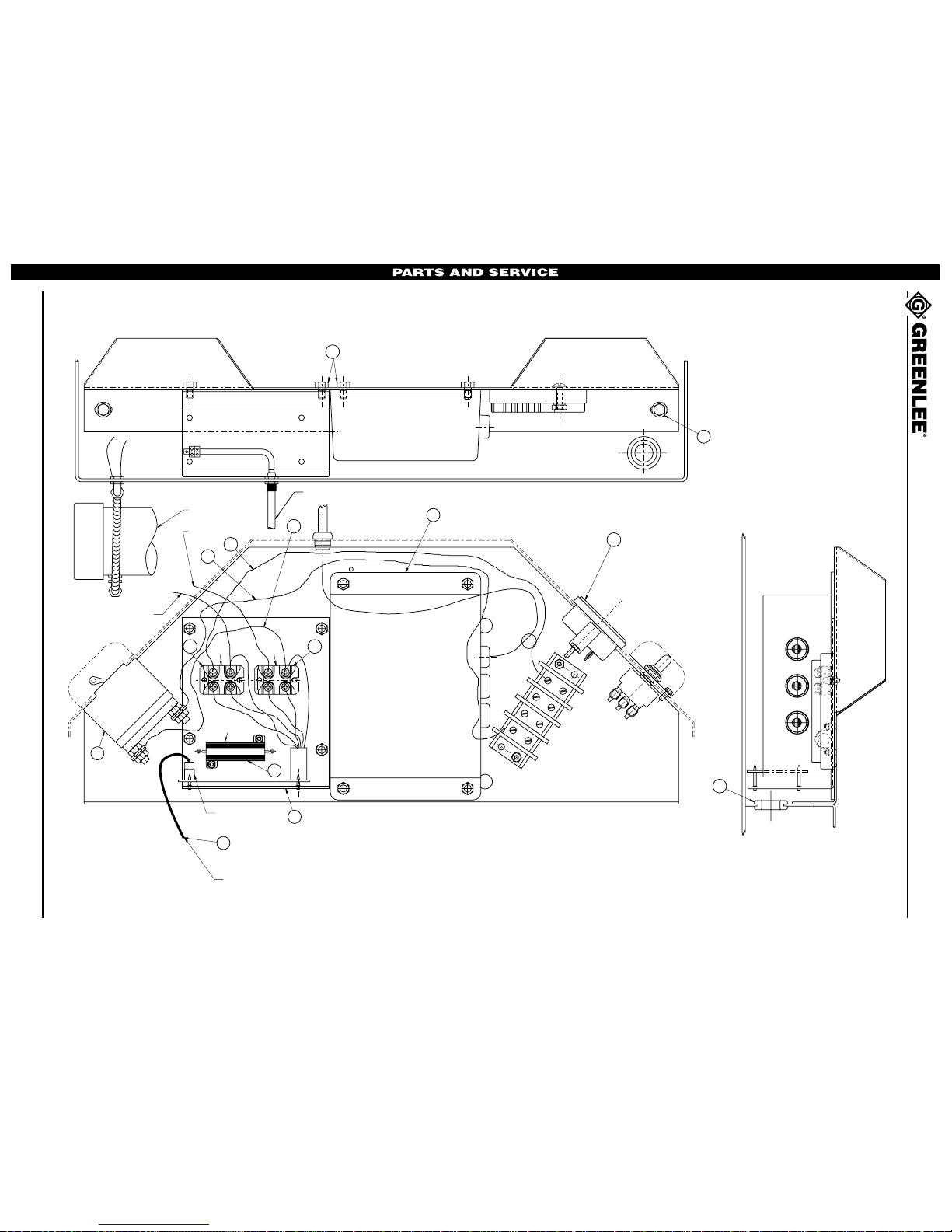
WHITE MOTOR LEAD
BLACK MOTOR LEAD
1
2
LOAD
LINE
MOTOR
PENDANT SWITCH
RECEPTACLE
PENDANT SWITCH CORD
PENDANT SWITCH
51
48
3
4
BATTERY #2
BATTERY #1
11
38
40
20
11
BLACK
RED
SEE THE NEXT PAGE
FOR A COMPLETE
TERMINAL BLOCK
WIRING ILLUSTRATION
BLACK
RED
RED
89
R101
Q102 Q101
88 88
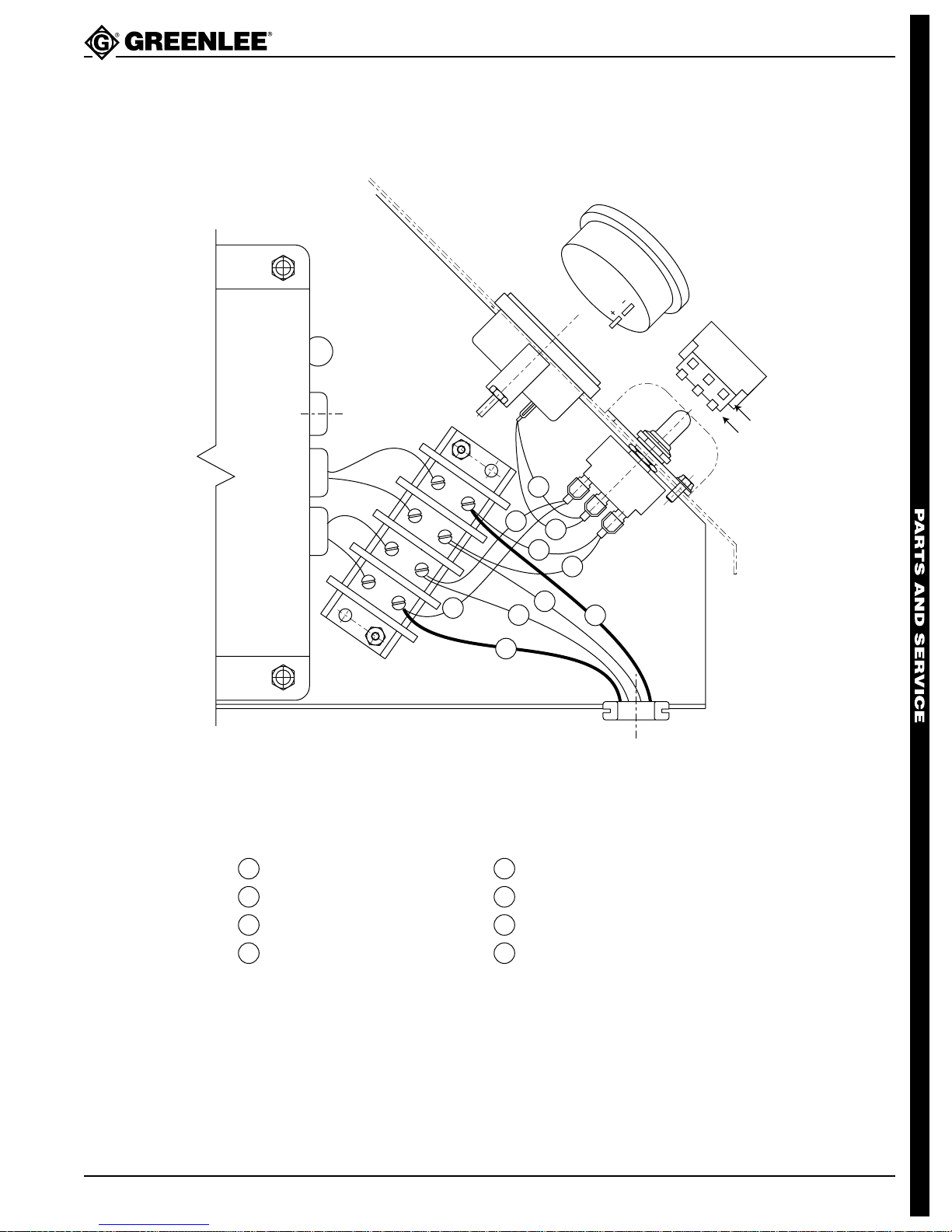
Wiring Layout—General
Page 35
555BAT™ Battery-Powered Bender
Wiring Layout—Terminal Block Detail
Wires (85) and (87) are not shown. See previous page.
BLACK
(+)
(–)
BATTERY #2
BATTERY #1
Gauge Wiring Notes: Connect red wire to positive (+) terminal of gauge.
Switch Wiring Notes: Connect red wires to terminals labeled (+).
70
Black (–) Battery Cable
74
Red Charger Cable with Fuse
BLACK
RED
RED
1
Connect black wire to negative (–) terminal of gauge.
Connect black wires to terminals labeled (–).
4
3
2
82
83
81
84
81
82
74
79
80
81
Black Wire (Terminal Block to Switch)
82
Red Wire (Terminal Block to Switch)
70
Black Charger Cable with Fuse
79
Red (+) Battery Cable
80
Greenlee Textron / Subsidiary of Textron Inc.
83
Red Wire (Switch to Gauge)
Black Wire (Switch to Gauge)
84
35
4455 Boeing Dr., Rockford, IL 61109-2988 815/397-7070
Page 36

Parts List
555BAT™ Battery-Powered Bender
Key UPC No. Part No. Description Qty.
1 04886 500 4886.4 Bracket, battery mounting .........................1
2 39742 503 9742.7 Frame ........................................................1
3 52646 905 2646.5 Nut, hex, 3/8–16 lock.................................1
4 55048 905 5048.0 Screw, 3/8–16 x 12.00 carriage.................1
5 54844 905 4844.2 Pin, hitch....................................................2
6 00487 500 4878.3 Base unit ...................................................1
7 54237 905 4237.1 Screw, flange, 3/8–16 x 1.00 .....................5
8 39758 503 9758.3 Eccentric cam............................................1
9 39763 503 9763.0 Countershaft eccentric ..............................1
10 53389 905 3389.5 Pin, hitch, .437 x 8.10 ................................2
11 54335 905 4335.1 Screw, thread-forming,
1/4–14 x .500 hex washer head ...............14
12 52413 905 2413.6 Bearing, thrust 1.50 x 2.62 x .093 .............2
13 52412 905 2412.8 Bearing, phenolic 1.50 x 1.62 x 1.00 .........2
14 39764 503 9764.8 Countershaft ..............................................1
15 39765 503 9765.6 Key, countershaft ......................................2
16 54253 905 4253.3 Sprocket, #60, 14 teeth .............................1
17 54546 905 4546.0 Chain, #60 ................................................ 1
18 54251 905 4251.7 Link, connecting, #60 chain .......................1
19 39760 503 9760.5 Cover, front................................................1
20 86349 918 6349.0 Grommet, rubber .625 x .875 x .312 .........3
21 52414 905 2414.4 Retaining ring, 2.375,
Truarc #5160-237......................................1
22 32896 503 2896.4 Sprocket, #60, 80 teeth .............................1
23 52410 905 2410.1 Bearing, phenolic 2.50 x 2.62 x 3.75 .........1
24 52409 905 2409.8 Bearing, phenolic 2.50 x 2.62 x 2.50 .........1
25 23452 502 3452.8 Washer, flat, 2.50 x 3.00 x .031, fiber........1
26 51528 905 1528.5 Retaining ring, .750,
Truarc #5160-75-SS-P ..............................4
27 51740 905 1740.7 Washer, flat .812 x 1.50 x .140..................3
28 86263 918 6263.9 Nut, conduit, 1/2" lock................................1
29 54279 905 4279.7 Cable tie, 11-inch ......................................1
30 54552 905 4552.4 Lanyard .....................................................1
31 50516 905 0516.6 Screw, machine,
#12–24 x .750 round head ........................2
32 39822 503 9822.9 Bracket, mounting, electrical .....................1
33 86901 918 6901.3 Terminal block ...........................................1
34 53370 905 3370.4 Washer, lock, .225 x .377 x .056 spring ....2
35 53369 905 3369.0 Nut, hex, #12–24 .......................................2
36 53936 905 3936.2 Screw, self-tapping,
#8–18 x .375 Phillips pan head .................2
37 04889 500 4889.9 Guard, switch ............................................1
38 05138 500 5138.5 Charger, battery ........................................1
Greenlee Textron / Subsidiary of Textron Inc.
36
4455 Boeing Dr., Rockford, IL 61109-2988 815/397-7070
Page 37

Parts List (cont’d)
Key UPC No. Part No. Description Qty.
39 86895 918 6895.5 Switch, double throw .................................1
40 00182 500 0182.5 Electronic control unit ................................1
41 55047 905 5047.1 Boot, toggle switch ....................................1
42 86896 918 6896.3 Gauge, battery...........................................1
43 51655 905 1655.9 Screw, thread forming #10–16 x .500 ......30
44 86899 918 6899.8 Bushing, strain relief ..................................1
45 04892 500 4892.9 Cover, top ..................................................1
46 50430 905 0430.5 Screw, machine,
47 04879 500 4879.1 Guard, switch ............................................1
48 86891 918 6891.2 Circuit breaker ...........................................1
49 54545 905 4545.1 Pin, hitch....................................................1
50 86767 918 6767.3 Strain relief ................................................1
51 39839 503 9839.3 Switch unit, pendant ..................................1
52 55045 905 5045.5 Plug, 5/8" dome .........................................1
53 55046 905 5046.3 Plug, 1-3/32" dome ....................................1
54 54551 905 4551.6 Chain, #40 .................................................1
55 52787 905 2787.9 Link, connecting #40 chain ........................1
56 54547 905 4547.8 Sprocket, #40, 13 teeth .............................1
57 39825 503 9825.3 Key, reducer sprocket ...............................1
58 52388 905 2388.1 Reductor ....................................................1
59 54568 905 4568.0 Bolt, 3/8–16 UNC x .750............................7
60 85214 918 5214.5 Elbow, pipe, 90 degree..............................1
61 54549 905 4549.4 Conduit, sealtight.......................................1
62 86892 918 6892.0 Motor, Electric, 24-volt...............................1
63 39769 503 9769.9 Guard, rear upper ......................................1
64 39768 503 9768.0 Guard, rear lower ......................................1
65 54548 905 4548.6 Sprocket, #40, 60 teeth .............................1
66 54023 905 4023.9 Retaining ring, 2.500,
67 04881 500 4881.3 Shaft, pivot ................................................1
68 53390 905 3390.9 Wheel, rubber, 12 x 3 ................................2
69 38166 503 8166.0 Axle ...........................................................1
70 05105 500 5105.9 Wire (black) ...............................................1
71 54764 905 4764.0 Nut, hex, 5/16–28 full ................................4
72 51602 905 1602.8 Washer, lock .323 x .586 x .078 spring .....4
73 52335 905 2335.0 Washer, flat .344 x .688 x .065..................8
74 05118 500 5118.0 Wire (red) ..................................................1
75 55058 905 5058.7 Screw, cap, 5/16–18 x 1.00 hex head .......4
76 86894 918 6894.7 Battery, lead-acid, 12-volt..........................2
77 86903 918 6903.0 Cover, battery terminal (red) .....................2
78 05104 500 5104.0 Wire (black) ...............................................1
555BAT™ Battery-Powered Bender
#6–32 x .375 slotted pan head ..................2
Truarc #5100-250......................................1
Greenlee Textron / Subsidiary of Textron Inc.
37
4455 Boeing Dr., Rockford, IL 61109-2988 815/397-7070
Page 38

Parts List (cont’d)
Key UPC No. Part No. Description Qty.
79 05114 500 5114.8 Wire (black) ...............................................1
80 05112 500 5112.1 Wire (red) ..................................................1
81 05094 500 5094.0 Wire (black) ...............................................2
82 05095 500 5095.8 Wire (red) ..................................................2
83 05098 500 5098.2 Wire (red) ..................................................1
84 05099 500 5099.0 Wire (black) ...............................................1
85 05122 500 5122.9 Wire (red) ..................................................1
86 05128 500 5128.8 Wire (red) ..................................................1
87 05131 500 5131.8 Wire (black) ...............................................1
88 86902 918 6902.1 FET, IXFN200N7 (Q101, Q102) ................2
89 86872 918 6872.6 Brake Resistor Unit (R101) .......................1
90 86911 918 6911.0 Cover, Battery Terminal (black).................2
Decals and Nameplate:
555BAT™ Battery-Powered Bender
86900 918 6900.5 Fuse, 15 Amp Bussman AGX15A .............2
04889 500 4899.6 Nameplate .................................................1
05093 500 5093.1 Decal, instruction .......................................1
05142 500 5142.3 Decal, identification ...................................1
05143 500 5143.1 Decal, battery selector switch....................1
05155 500 5155.5 Decal, safety..............................................1
30392 503 0392.9 Decal, damp warning.................................1
33937 503 3937.0 Decal, Squeeze Adjust ..............................1
38974 503 8974.2 Decal, Circuit Breaker ...............................1
Literature:
Battery charger manufacturer’s instructions
MSDS for lead/acid batteries
Greenlee Textron / Subsidiary of Textron Inc.
38
4455 Boeing Dr., Rockford, IL 61109-2988 815/397-7070
Page 39
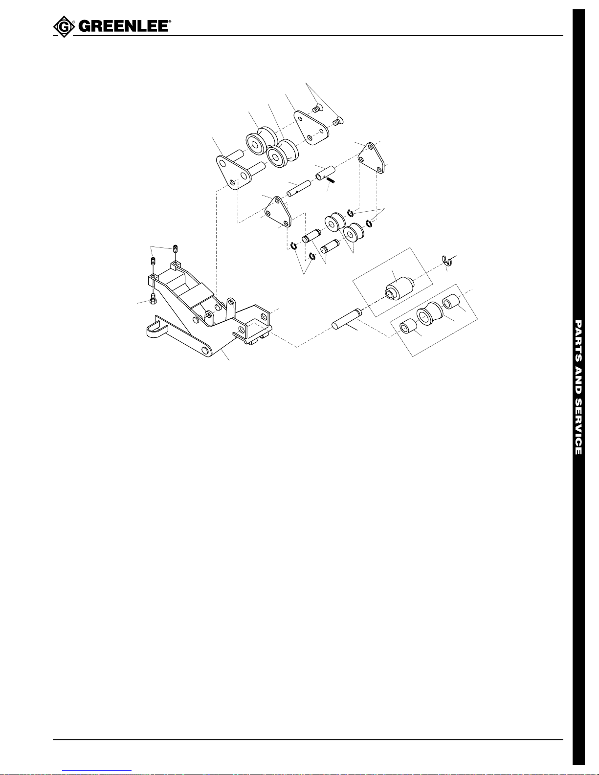
Roller Support Units
555BAT™ Battery-Powered Bender
8
7
6
5
4
3
2
1
EMT Roller Support Unit
9
11
10
9
13
12
14
15
16
13
EMT
17
18
20
18
19
IMC
Key Part No. Description Qty.
502 3541.9 Roller Support Unit, 1-1/2" – 2" EMT
1 502 3539.7 Frame unit, roller support..............................................1
2 905 0542.5 Screw, cap, 1/2–13 x 1.00 hex head ............................2
3 905 2848.4 Screw, set, 1/2–13 x .750 slotted..................................2
4 503 4964.3 Support, 2" roller ...........................................................1
5 502 3519.2 Roller, 2" EMT, front .....................................................1
6 502 3792.6 Roller, 2" EMT, back .....................................................1
7 503 4965.1 Plate, 2" inner roller support .........................................1
8 905 3394.1 Screw, machine, 7/16–14 UNC x 1.00 flat head ...........2
9 502 3524.9 Plate, pivot, 1-1/2 roller .................................................2
10 502 3517.6 Pin, roller pivot ..............................................................1
11 502 3793.4 Spacer, .782 x 1.00 x 2.21 ............................................1
12 905 1491.2 Pin, roll, .187 x 1.25 ......................................................1
13 905 1528.5 Retaining ring, .750, Truarc #5160-75-SS-P ................4
14 502 3932.5 Pin, 1-1/2" roller, .749 x 3.09 ........................................2
15 502 3510.9 Roller, cushioned, 1-1/2" EMT ......................................2
16 502 3511.7 Pin, roller support, .998 x 4.81 ......................................1
17 502 7983.1 Roller, cushioned, EMT ................................................1
20 905 2464.0 Retaining ring, 1.000, Truarc # 5133-98 .......................1
Greenlee Textron / Subsidiary of Textron Inc.
39
4455 Boeing Dr., Rockford, IL 61109-2988 815/397-7070
Page 40

555BAT™ Battery-Powered Bender
Roller Support Units (cont’d)
IMC Roller Support Unit
Key Part No. Description Qty.
502 5273.9 Roller Support Unit, 1-1/2" – 2" IMC
1 502 6325.0 Frame unit, roller support..............................................1
2 905 0542.5 Screw, cap, 1/2–13 x 1.00 hex head ............................2
3 905 2848.4 Screw, set 1/2–13 x .750 slotted...................................2
4 503 4964.3 Support, 2" roller ...........................................................1
5 502 5279.8 Roller, 2" IMC................................................................2
7 503 4965.1 Plate, 2" inner roller support ........................................1
8 905 3394.1 Screw, machine, 7/16–14 UNC x 1.00 flat head ...........2
9 502 3524.9 Plate, pivot, 1-1/2 roller .................................................2
10 502 3517.6 Pin, roller pivot ..............................................................1
11 502 3793.4 Spacer, .782 x 1.00 x 2.21 ............................................1
12 905 1491.2 Pin, roll, .187 x 1.25 ......................................................1
13 905 1528.5 Retaining ring, .750, Truarc #5160-75-SS-P ................4
14 502 3932.5 Pin, 1-1/2" roller, .749 x 3.09 ........................................2
15 502 5274.7 Roller, 1-1/2" IMC .........................................................2
16 502 3511.7 Pin, roller support, .998 x 4.81 ......................................1
18 502 8335.9 Spacer, 1.01 x 1.62 x .730 ............................................2
19 502 8334.0 Roller, IMC ....................................................................1
20 905 2464.0 Retaining ring, 1.000, Truarc # 5133-98 .......................1
Greenlee Textron / Subsidiary of Textron Inc.
40
4455 Boeing Dr., Rockford, IL 61109-2988 815/397-7070
Page 41
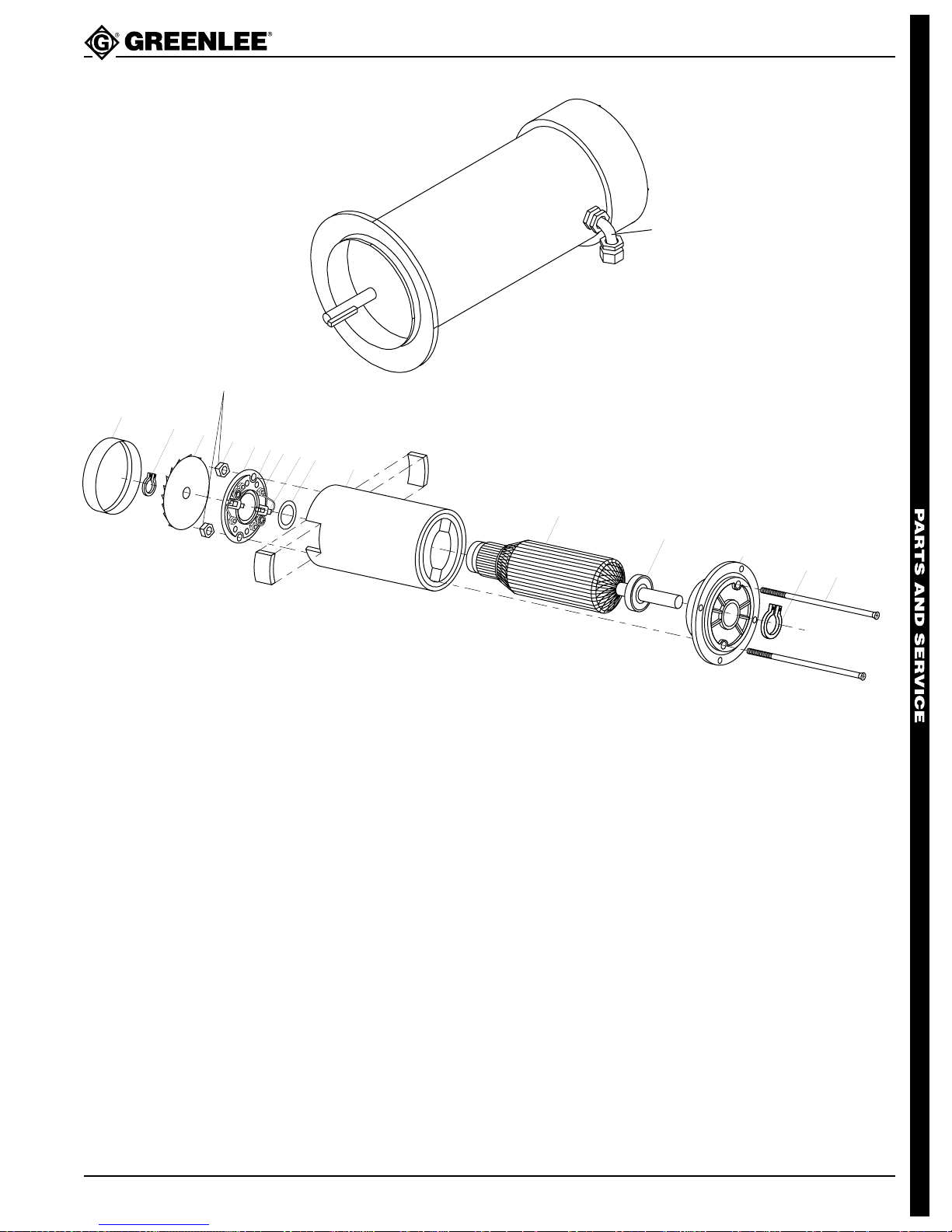
Motor—24 V olt
Torque to
80 inch-pounds
555BAT™ Battery-Powered Bender
1
2
3
4
5
6
7
8
9
10
11
12
13
Key No. Part No. Description Qty.
918 6892.0 Motor, 24 Volt ........................................................1
1 918 5876.3 90° Connector........................................................1
2 918 6471.2 Fan Cover ..............................................................1
3 905 5071.4 Retaining Ring .......................................................1
4 918 6432.1 Fan ........................................................................1
5 918 6428.3 End Bell Nut...........................................................2
6 918 6908.0 Bell, Rear End .......................................................1
7 918 6430.5 Brush Cover...........................................................2
8 918 6431.3 Screw.....................................................................7
9 918 6909.9 Brush .....................................................................2
10 918 6422.4 Thrust Washer .......................................................1
11 918 6906.4 Shell & Magnet Assembly, 24 Volt ........................1
12 918 6907.2 Armature, 24 Volt...................................................1
13 918 6421.6 Bearing ..................................................................2
14 918 6418.6 Bell, Front End .......................................................1
15 918 6424.0 Retaining Ring .......................................................1
16 918 6426.7 Tie Bolt ..................................................................2
14
15
16
Greenlee Textron / Subsidiary of Textron Inc.
41
4455 Boeing Dr., Rockford, IL 61109-2988 815/397-7070
Page 42
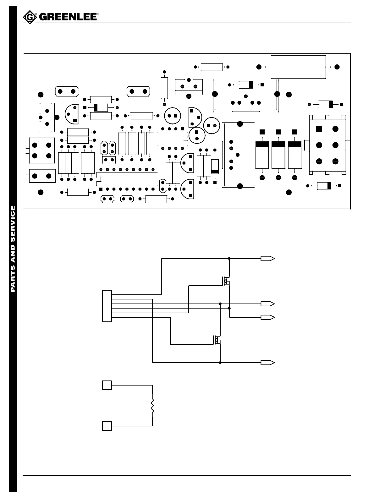
Control Assembly
GREENLEE TEXTRON
J3
Q6
R18
Q3
J1
555BAT™ Battery-Powered Bender
5000183.3
REV 1
R1
R23
C1J5C2
J4
R19
D3
R11R14
R17
R20
C3
+
R8
R9
U2
R21
D6
U3
C6
+
+
C4
R16
R13
R22
Q4
D5
D4
D8
D9
D7
43
21
1
2
R4
R5R3 R2
R7
To J2 on Printed
Circuit Board
Y1
R6
U1
PIC16C620
C7
C8
J101
1
2
3
4
5
6
AMP 350715-1
R15
C5
R10
R12
Q1
D1
Q2
YELLOW
BLUE
G
D S
Q102
G
IXFN200N07
D S
Q101
IXFN200N07
Q5
RED
GRAY
WHITE
BATTERY +24
MOTOR-BLACK LEAD
MOTOR-WHITE LEAD
J2
D2
J102
1
WHITE
To J3, J4 on Printed
Circuit Board
J103
1
Greenlee Textron / Subsidiary of Textron Inc.
WHITE
R101
1 OHM, 50 W
42
BLACK
BATTERY GROUND
4455 Boeing Dr., Rockford, IL 61109-2988 815/397-7070
Page 43
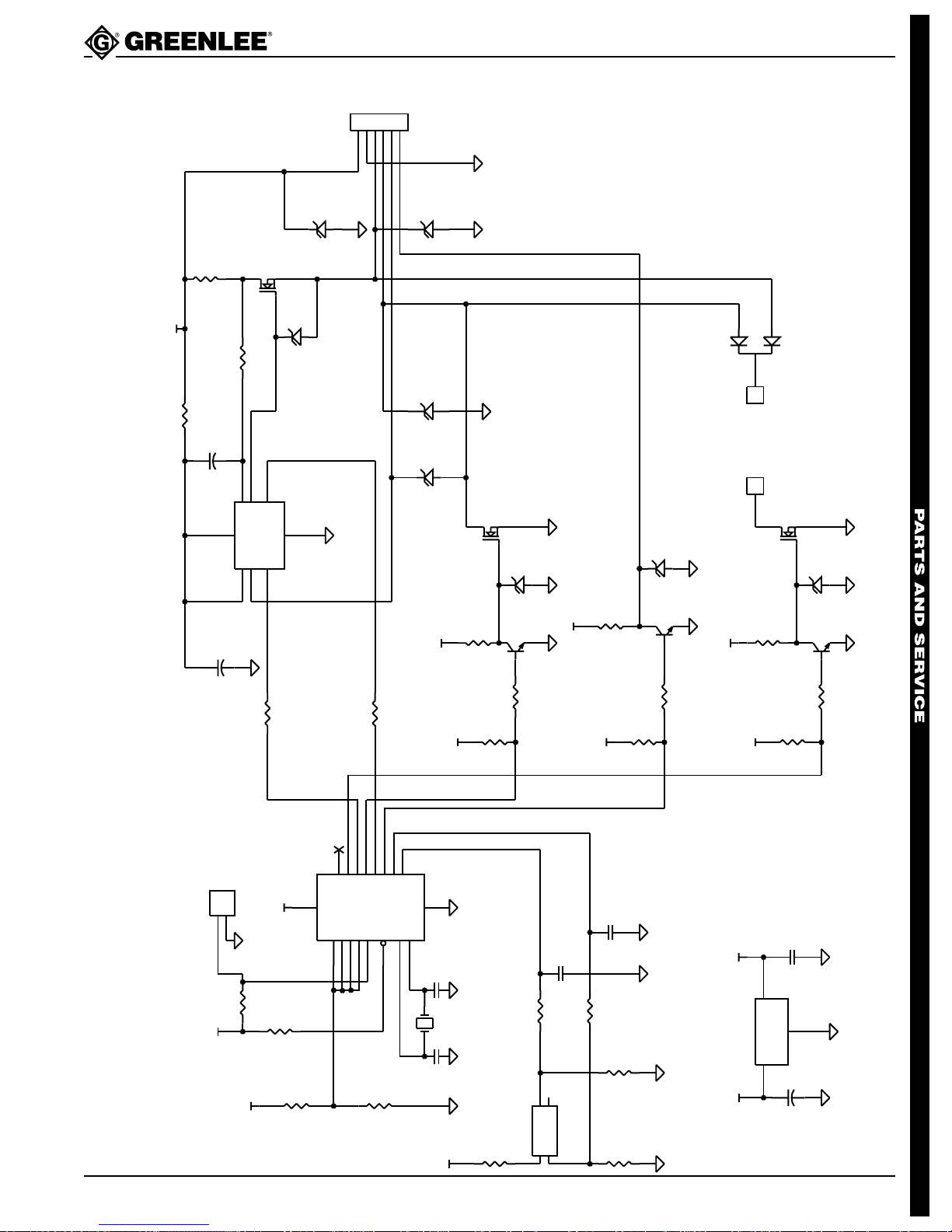
555BAT™ Battery-Powered Bender
Control Assembl y (cont’d)
D7
1.5KE33A
Q4
100K
8
DS 2
Vss6GND
DS 1
1
IRF3205
D S
G
7
5
IN 2
GATE 2
GATE 12IN 1
4
D5
1N5242
AC
3
R20
+24V
10
+24
.005, 5W
R22
R21
C4
4.7
+
U2
LTC1255
J2
AC
12345
6
AMP 350711-1
D9
D8
D4
1.5KE33A
1.5KE33A
1N5242
AC
Q5
IRF3205
D S
G
123
D6
J4
To Brake
J3
D2
1N5242
D1
1N5242
AC
AC
1
Resistor
1
FEP16BT
Q6
IRF1010N
D S
G
D3
1N5242
AC
C3
+
J5
+5V
47
R9
1
2
MOLEX 39-28-1023
R23
10K
+24V
10K
+5V
R8
U1
10K
R6
69.8K, 1%
14
Vdd
PIC16C620
R10
Bend High
Brake
13
RA21RA32RA43MCLR
RA017RA1
18
10K
Bend Low
Unload Low
Unload High
4
R7
10K, 1%
RB06RB17RB28RB39RB410RB511RB612RB7
Vss
OSC116OSC2
15
Y1
+24V
5
C2
C1
100p
1 MHz
100p
+5V
R13
15K
R11
4.7K
Q1
2
2N3904
R12
R5
10K
13
4.7K
Unload Input
2
4
R16
15K
+24V
+5V
Bend Input
C8
C7
.1
R4
10K
R3
Q2
2N3904
13
2
4.7K
R15
R14
4.7K
.1
1K
+24V
+5V+24V
U3
+5V
V78L05
R19
1
3
15K
VO
VI
GND
R17
C6
+
4.7K
C5
10
Q3
2N3904
13
2
R18
4.7K
.1
2
Greenlee Textron / Subsidiary of Textron Inc.
+5V
43
R1
100
J1
1
3
MOLEX 39-28-1043
R2
1K
4455 Boeing Dr., Rockford, IL 61109-2988 815/397-7070
Page 44

555BAT™ Battery-Powered Bender
Control Assembly (cont’d)
Electronic Components
Reference Supplier Model/Part No. Description Qty.
C1,2 generic Capacitor 100ρF 50V ...............................2
C3 generic Capacitor 47µF 50V ................................. 1
C4 generic Capacitor 4.7µF 50V ................................ 1
C5,7,8 generic Capacitor .1µF 50V .................................. 3
C6 generic Capacitor 10µF 50V ................................. 1
D1,2,3,4,5 Microsemi or equiv. 1N5242 Zener Diode 12V 500 mW........................5
D6 General Semiconductor FEP16BT Fast dual diode.........................................1
D7,8,9 Motorola or equiv. 1.5KE33A Transient suppressor diode .....................3
J1 MOLEX 39-28-1043 Connector.................................................1
J2 AMP 350711-1 Connector.................................................1
J3,4 Keystone 1287 Quick-connect male tab 1/4 x .032 ..........2
Q1,2,3 generic 2N3904 Transistor NPN.........................................3
Q4,5 International Rectifier IRF3205 MOSFET N-channel................................. 2
Q6 International Rectifier IRF1010N MOSFET N-channel.................................1
R1 generic Resistor 100 1/4W 5% CF........................1
R2,3 generic Resistor 1K 1/4W 5% CF .........................2
R4,5,8,9,10 generic Resistor 10K 1/4W 5% CF .......................5
R6 generic Resistor 69.8K 1/4W 1% MF....................1
R7 generic Resistor 10K 1/4W 1% MF.......................1
R11,12,14, 15,17,18 generic Resistor 4.7K 1/4W 5% CF ...................... 6
R13,16,19 generic Resistor 15K 1/4W 5% CF .......................3
R20 generic Resistor 10 ohm 1/4W 5% CF .................1
R21 generic Resistor 100K 1/4W 5% CF .....................1
R22 Dale LVR-5-.005 Resistor .005 ohm 5W 1% .......................1
U1 Greenlee Textron 9186910.2 Programmed microprocessor................... 1
U2 Linear Technology LTC1255-N8 Integrated Circuit ......................................1
U3 Motorola or equiv. LM78L05 Voltage regulator, 5 volts .........................1
Y1 ECS ZTB1000J Ceramic resonator, 1 MHz .......................1
Miscellaneous Components
Reference Supplier Model/Part No. Description Qty.
Q4,5 Thermalloy 6221PB Heat Sink.................................................. 2
D6 AAVID 577002B04000 Heat sink .................................................. 1
Q4,5,D6 generic Screw 4–40 x 3/8 ..................................... 3
Q4,5,D6 generic Nut with captive lock washer, 4–40.......... 3
U1 generic socket, 18 PIN..........................................1
Greenlee Textron / Subsidiary of Textron Inc.
44
4455 Boeing Dr., Rockford, IL 61109-2988 815/397-7070
Page 45
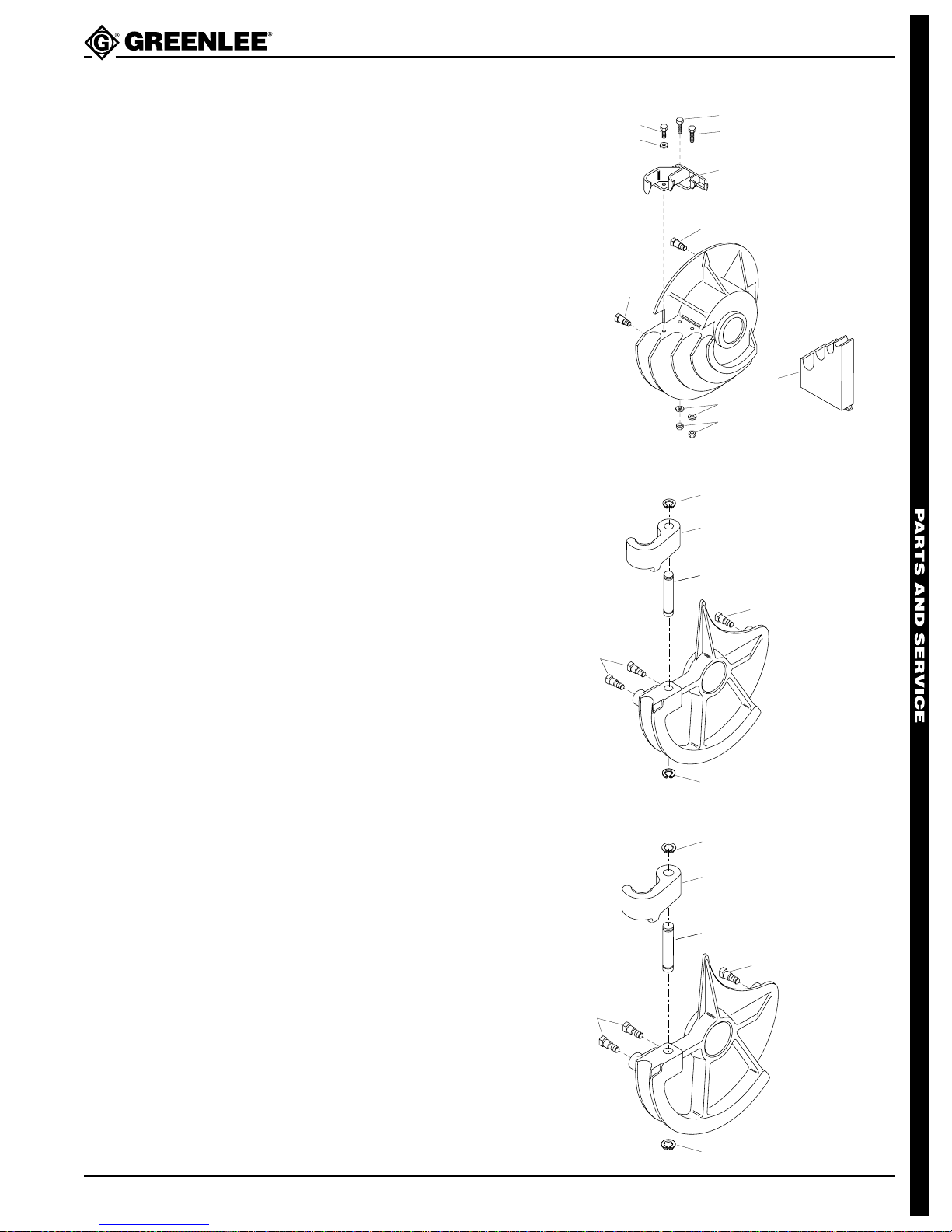
555BAT™ Battery-Powered Bender
1
2
3
4
4
1
1
2
3
4
4
1
Bending Shoes and Roller Supports
1/2" – 1-1/4" EMT
501 7944.6 Shoe Unit
(includes keys 1 - 6).......................1
1 905 1088.7 Screw, cap,
3/8–16 x 1.25 socket head.............2
2 905 0597.2 Screw, cap,
3/8–16 x 1.00 socket head.............1
3 905 0506.9 Washer, lock,
.388 x .673 x .070 ..........................3
4 502 4555.4 Hook .............................................. 1
5 502 3422.6 Stud, drive......................................4
6 905 0639.1 Nut, hex, 3/8–16 ............................ 2
7 501 7986.1 Support Unit................................... 1
2
3
5
1
1
4
5
7
3
6
1-1/2" EMT
502 3499.4 Shoe Unit (includes keys 1 - 4)...... 1
1 905 1529.3 Retain. ring, .875,
Truarc # 5160-87 ...........................2
2 501 8820.8 Hook .............................................. 1
3 501 8841.0 Pin, hook........................................ 1
4 502 3422.6 Stud, drive......................................3
2" EMT
502 3505.2 Shoe Unit (includes keys 1 - 4)...... 1
1 905 1529.3 Retain. ring, .875,
Truarc # 5160-87 ...........................2
2 501 8818.6 Hook .............................................. 1
3 501 8842.9 Pin, hook........................................ 1
4 502 3422.6 Stud, drive......................................3
Greenlee Textron / Subsidiary of Textron Inc.
45
4455 Boeing Dr., Rockford, IL 61109-2988 815/397-7070
Page 46
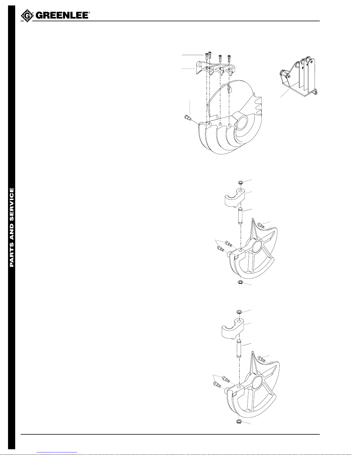
555BAT™ Battery-Powered Bender
1
2
3
4
4
1
1
2
3
4
1
2
3
4
4
1
Bending Shoes and Roller Supports (cont’d)
1/2" – 1-1/4" IMC and Rigid Steel
500 0571.5 Shoe Unit (includes keys 1 - 3)...... 1
1 905 1088.7 Screw, cap,
3/8"–16 x 1.25 socket head ........... 4
2 500 0569.3 Hook .............................................. 1
3 502 3422.6 Stud, drive......................................3
4 500 0936.2 Roller Support Unit ........................ 1
For 1-1/2" IMC
502 5263.1 Shoe Unit (includes keys 1 - 4)......1
1 905 1528.5 Retaining ring, .750,
Truarc #5160-75-SS-P...................2
2 501 8811.9 Hook .............................................. 1
3 501 8837.2 Pin, hook........................................ 1
4 502 3442.6 Stud, drive......................................3
For 2" IMC
1 905 1529.3 Retaining ring, .875,
2 500 0195.7 Hook .............................................. 1
3 501 8842.9 Pin, hook........................................ 1
4 502 3422.6 Stud, drive......................................3
502 5268.2 Shoe Unit (includes keys 1 - 4)......1
Truarc #5160-87 ............................2
Greenlee Textron / Subsidiary of Textron Inc.
46
4455 Boeing Dr., Rockford, IL 61109-2988 815/397-7070
Page 47

555BAT™ Battery-Powered Bender
Bending Shoes and Roller Supports (cont’d)
For 1-1/2" – 2" Rigid Steel
501 7937.3 Shoe Unit (includes keys 1 - 7)...... 1
1 905 2426.8 Screw, cap,
5/8–11 x 4.00 socket head.............1
2 501 7974.8 Pivot............................................... 1
3 501 7969.1 Hook .............................................. 1
4 502 3422.6 Stud, drive......................................4
5 905 2675.9 Washer, flat, .687 x 1.75 x .125.....1
6 905 0905.6 Washer, lock,
.645 x .923 x .203 spring ............... 1
7 905 1569.2 Nut, hex, 5/8–11 ............................ 1
8 501 7984.5 Roller Support Unit ........................ 1
1
2
3
4
4
8
5
6
7
For 1/2" – 1-1/4" 40-Mil PVC Coated Rigid Conduit
500 0573.1 Shoe Unit (includes 1 - 3) ..............1
1 905 1088.7 Screw, cap,
3/8–16 x 1.25 socket head.............4
2 500 0570.7 Hook .............................................. 1
3 502 3422.6 Stud, drive......................................3
4 500 0946.0 Roller Support Unit
(includes keys 5 - 13).....................1
5 500 0930.3 1-1/4" Roller...................................1
6 905 1353.3 Retaining ring, .500,
Truarc #5160-50-S-PP...................5
7 500 0927.3 1/2" Roller ...................................... 1
8 500 0928.1 3/4" Roller ...................................... 1
9 500 0929.0 1" Roller ......................................... 1
10 500 0923.0 1/2" Roller axle ..............................1
11 500 0924.9 3/4" Roller axle ..............................1
12 500 0925.7 1" Roller axle ................................. 1
13 500 0926.5 1-1/4" Roller axle ...........................1
7
8
9
10
11
12
1
6
2
3
13
4
5
6
6
6
6
Greenlee Textron / Subsidiary of Textron Inc.
47
4455 Boeing Dr., Rockford, IL 61109-2988 815/397-7070
Page 48
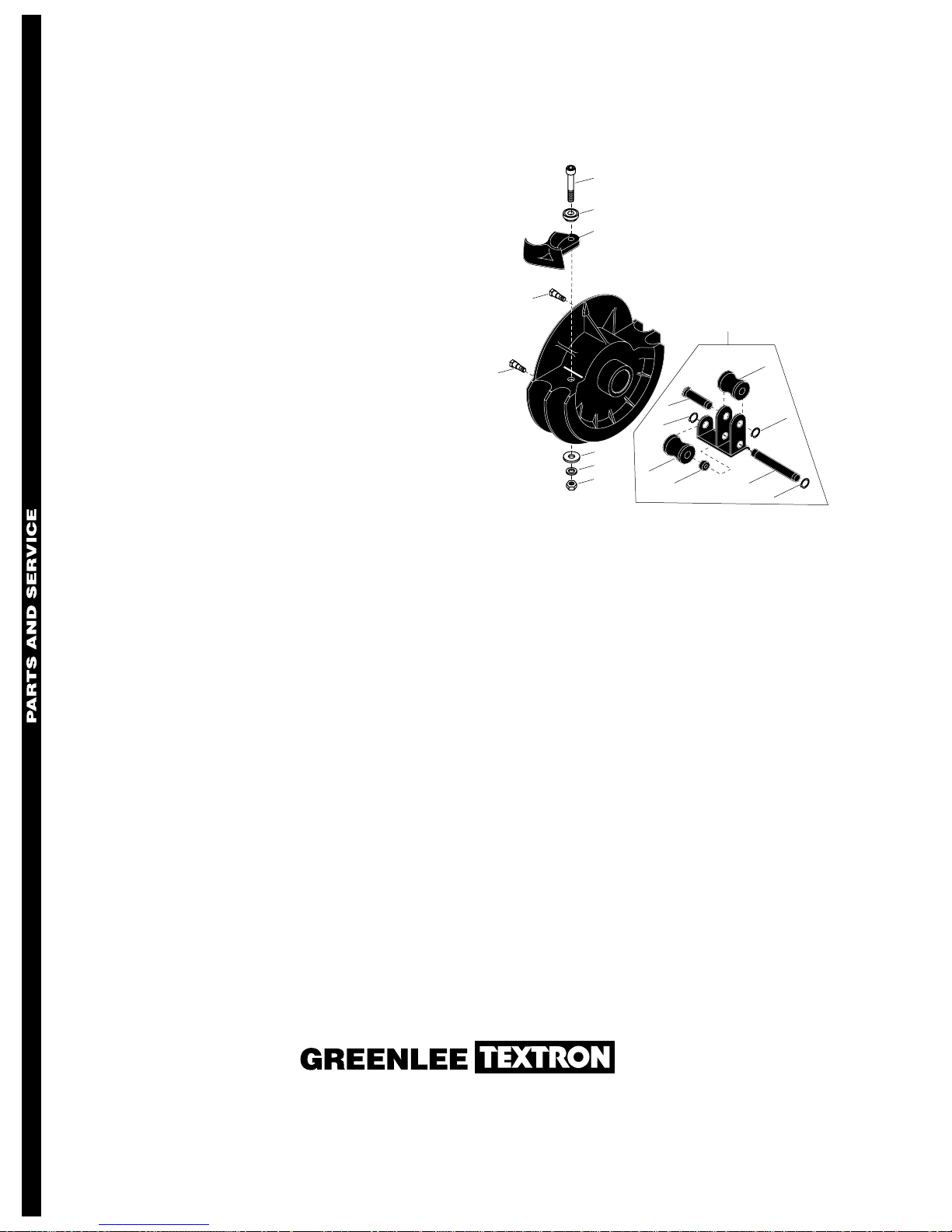
Bending Shoes and Roller Supports (cont’d)
For 1-1/2" – 2" 40-Mil PVC Coated Rigid Conduit
503 7281.5 Shoe Unit (includes keys 1 - 7)......1
1 905 2426.8 Screw, cap,
5/8–11 x 4.00 socket head.............1
2 501 7974.8 Pivot............................................... 1
3 500 2499.0 Hook .............................................. 1
4 502 3422.6 Stud, drive......................................4
5 905 2675.9 Washer, flat, .687 x 1.75 x .125.....1
6 905 0905.6 Washer, lock,
.645 x .923 x .203 spring ............... 1
7 905 1569.2 Nut, hex, 5/8–11 ............................ 1
8 503 7282.3 Roller Support Unit
(includes keys 9 - 14).....................1
9 503 7284.0 1-1/2" Roller...................................1
10 503 7662.4 1-1/2" Roller axle ...........................1
11 905 1528.5 Retaining ring, .750,
Truarc #5160-75-SS-P...................3
12 503 7283.1 2" Roller ......................................... 1
13 503 7661.6 2" Roller axle ................................. 1
14 503 2025.4 Spacer ........................................... 1
1
2
3
4
8
4
10
11
5
6
12
7
14
9
11
13
11
Greenlee Textron / Subsidiary of Textron Inc.
4455 Boeing Drive, Rockford, IL 61109-2988 USA
Customer Service (International): 815/397-7070 • Fax: 815/397-1391
Customer Service (North America): 800/435-0786 • Fax: 800/451-2632, 815/397-1865
Canada Fax: 800/524-2853 Printed in the U.S.A.
 Loading...