

Page 1
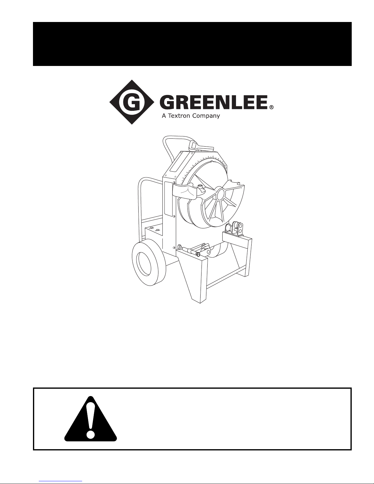
INSTRUCTION MANUAL
Electric Bender
999 1817.0 © 2004 Greenlee Textron Inc. IM 1227 REV 7 6/04
555®-22
Read and understand all of the instructions and
safety information in this manual before operating
or servicing this tool.
Page 2

555®-22 Electric Bender
Table of Contents
Description .....................................................................2
Safety ............................................................................. 2
Purpose.......................................................................... 2
Important Safety Information...................................... 3–4
Grounding Instructions ................................................... 5
Identification ................................................................... 6
Specifications ................................................................. 6
Bending Attachment Groups .......................................... 7
Setup.............................................................................. 8
Operation ................................................................. 9–11
Illustrated Bending Glossary ........................................12
Bending Instructions...............................................13–14
Additional Bending Instructions.............................. 15–24
Handle Removal and Replacement ............................. 25
Transportation .............................................................. 25
Maintenance...........................................................26–27
Troubleshooting ..................................................... 28–29
Exploded Views and Parts Lists............................. 30–33
Schematic Diagrams and Parts Lists .....................34–38
Bending Shoes and Roller Supports ...................... 39–43
Safety
Safety is essential in the use and maintenance of
Greenlee tools and equipment. This instruction manual
and any markings on the tool provide information for
avoiding hazards and unsafe practices related to the
use of this tool. Observe all of the safety information
provided.
Purpose
This manual is intended to familiarize all personnel with
the safe operation and maintenance procedures for the
following Greenlee tool:
555®-22 Electric Bender, with Serial Code AAN
Keep this manual available to all personnel.
Replacement manuals are available upon request at no
charge.
Description
The Greenlee 555®-22 Electric Bender is intended to
bend 1/2" to 2" conduit and pipe.
Bending shoe groups are available to accommodate the
following types: Electrical Metallic Tubing, Intermediate
Metallic Conduit, Rigid Conduit, PVC-Coated Rigid
Conduit, and Schedule 40 Pipe. The shoe groups are
shown in the Bending Attachment Groups section of this
manual.
In addition to the 555®-22, this manual also applies to
the following accessories:
• EMT Shoe Group (includes accessories for bending
Electrical Metallic Tubing)
•IMC Shoe Group (includes accessories for bending
Intermediate Metallic Conduit)
• Rigid Shoe Group (includes accessories for bending
Rigid Conduit and Schedule 40 Pipe)
All specifications are nominal and may change as design improvements occur. Greenlee Textron Inc. shall not be liable for damages
resulting from misapplication or misuse of its products.
Mobil is a registered trademark of Mobil Oil Corporation.
Greenlee / A Textron Company 2 4455 Boeing Dr. • Rockford, IL 61109-2988 USA • 815-397-7070
KEEP THIS MANUAL
Page 3
IMPORTANT SAFETY INFORMATION
SAFETY
ALERT
SYMBOL
This symbol is used to call your attention to hazards
or unsafe practices which could result in an injury or
property damage. The signal word, defined below,
indicates the severity of the hazard. The message
after the signal word provides information for
preventing or avoiding the hazard.
Immediate hazards which, if not avoided, WILL
result in severe injury or death.
555®-22 Electric Bender
Electric shock hazard:
• Connect the power cord to a 220
volt, 15 amp receptacle on a
ground fault protected circuit only.
See Grounding Instructions.
• Do not modify the power cord or
plug.
• Inspect the power cord before use.
Repair or replace the cord if
damaged.
• Disconnect from power before
servicing.
Failure to observe this warning could
result in severe injury or death.
Hazards which, if not avoided, COULD result in
severe injury or death.
Hazards or unsafe practices which, if not avoided,
MAY result in injury or property damage.
Read and understand all of the
instructions and safety information
in this manual before operating or
servicing this tool.
Failure to observe this warning will
result in severe injury or death.
Do not use this tool in a hazardous
environment. Hazards include
flammable liquids, gases, or other
materials. Using this tool in a hazardous environment can result in a
fire or explosion.
Failure to observe this warning will
result in severe injury or death.
• Do not expose to rain.
• Do not use in wet or damp
locations.
Failure to observe these warnings
could result in severe injury or death.
Wear eye protection when operating
or servicing this tool.
Failure to wear eye protection could
result in serious eye injury from
flying debris.
Do not remove guards.
Failure to observe this warning could
result in severe injury or death.
Greenlee / A Textron Company 3 4455 Boeing Dr. • Rockford, IL 61109-2988 USA • 815-397-7070
Page 4
555®-22 Electric Bender
IMPORTANT SAFETY INFORMATION
Extension cords:
• Use only three-wire, 12-gauge
extension cords that have threeprong grounding-type plugs and
three-hole receptacles that accept
the tool’s plug.
• Do not use extension cords that
are longer than 30 m (100').
• Repair or replace damaged
extension cords.
Failure to observe these warnings
could result in severe injury or death.
Make sure that the handle is properly installed and
secured with the safety spring clips and snap pins
before lifting or moving the bender. An improperly
installed handle could allow the bender to fall,
injuring nearby personnel.
Failure to observe this warning could result in
severe injury or death.
Do not use as a step or ladder.
• Conduit moves rapidly as it is bent. The path of
the conduit must be clear of obstructions. Be sure
clearance is adequate before starting the bend.
• Do not operate the bender while wearing loose
clothing. Loose clothing can get caught in moving
parts.
• Inspect the bender before use. Replace worn,
damaged or missing parts with Greenlee replacement parts. A damaged or improperly assembled
component could break and strike nearby personnel.
• Some bender parts and accessories are heavy
and may require more than one person to lift and
assemble.
• Use this tool for the manufacturer’s intended
purpose only. Use other than that which is
instructed in this manual can result in injury or
property damage.
Failure to observe these precautions may result in
injury or property damage.
Pinch points:
Keep hands away from bending
shoe, rollers and conduit when
bender is in use.
Failure to observe this warning could
result in severe injury or death.
Unplug the bender before changing accessories.
Accidental startup could result in serious injury.
Greenlee / A Textron Company 4 4455 Boeing Dr. • Rockford, IL 61109-2988 USA • 815-397-7070
Page 5
Grounding Instructions
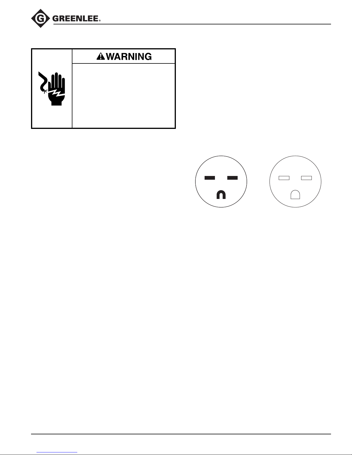
ReceptaclePlug
Electric shock hazard:
• Do not modify the plug provided
with the tool.
• Connect this tool to a grounded
receptacle on a 15 amp ground
fault protected circuit.
Failure to observe this warning could
result in severe injury or death.
555®-22 Electric Bender
This tool must be grounded. In the event of a malfunction or breakdown, an electrical ground provides a path
of least resistance for the electric current. This path of
least resistance is intended to reduce the risk of electric
shock.
This tool’s electric cord has a grounding conductor and
a grounding plug as shown. Do not modify the plug.
Connect the plug to a corresponding GFCI-protected
receptacle that is properly installed and grounded in
accordance with all national and local codes and
ordinances.
Do not use an adapter.
NEMA 6-15
Greenlee / A Textron Company 5 4455 Boeing Dr. • Rockford, IL 61109-2988 USA • 815-397-7070
Page 6
Identification
555®-22 Electric Bender
1
2
3
4
5
6
Specifications
Height.................................................................................................... 1118 mm (44")
Width.................................................................................................... 724 mm (28.5")
Depth ................................................................................................... 521 mm (20.5")
Mass/Weight (bender without shoes or roller supports)....................... 118 kg (260 lb)
Power Supply....................................................................................220 VAC, 15 amp
Operating Conditions
Capacity ............................................................... 1/2" to 2" conduit, schedule 40 pipe
8
7
555®-22 Electric Bender
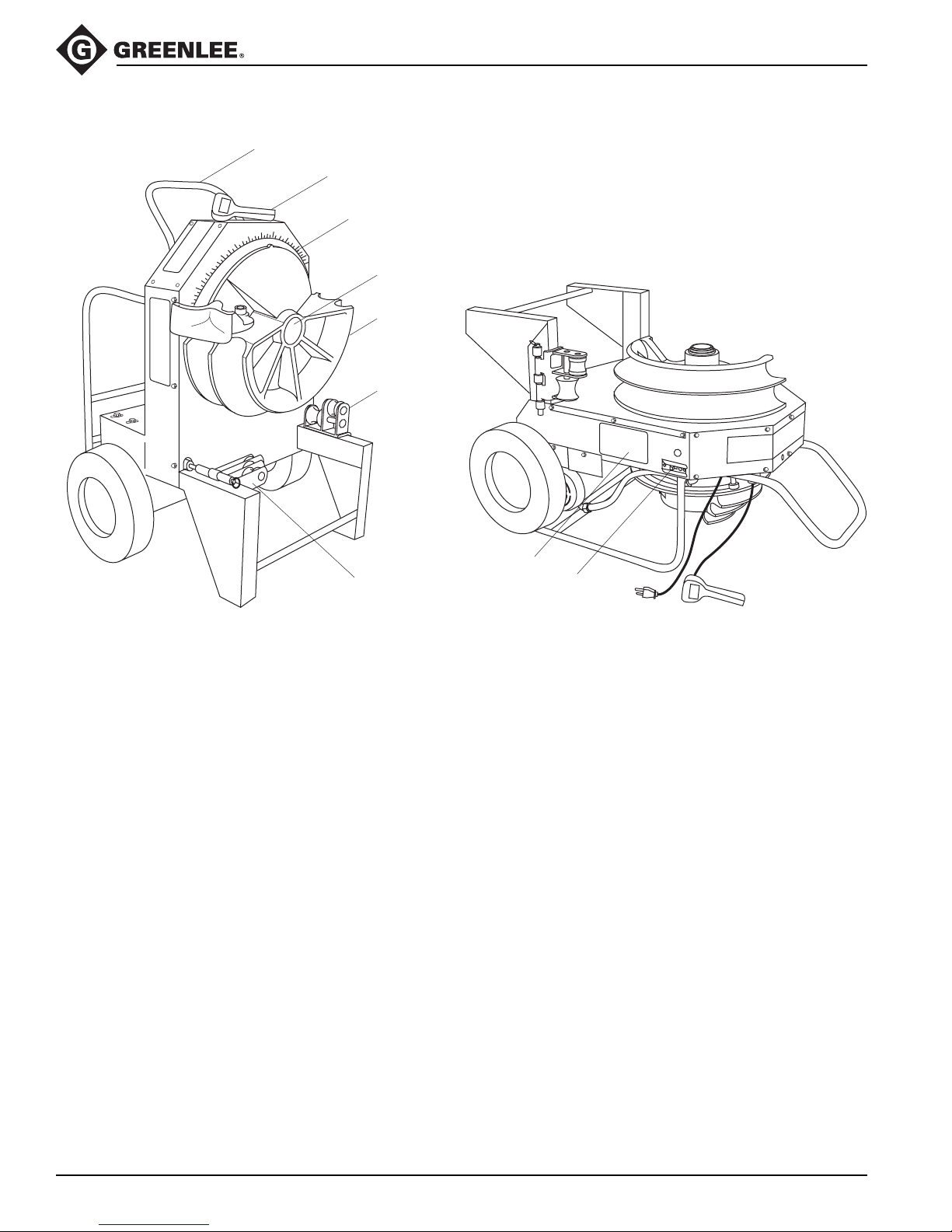
1. Handle
2. Pendant
3. Protractor
4. Main Shaft
5. Bending Shoe
Temperature......................................................–20 °C to 49 °C (–5 °F to 120 °F)
Relative Humidity ..................................................................................... 0 to 98%
6. 1-1/2" to 2" Roller Support
7. 1/2" to 1-1/4" Roller Support
(in storage position)
8. Bending Instructions Decal
9. Circuit Breaker (ON/OFF switch)
9
GFCI-protected receptacle
Greenlee / A Textron Company 6 4455 Boeing Dr. • Rockford, IL 61109-2988 USA • 815-397-7070
Page 7
Bending Attachment Groups
555®-22 Electric Bender
RIGID
1
34
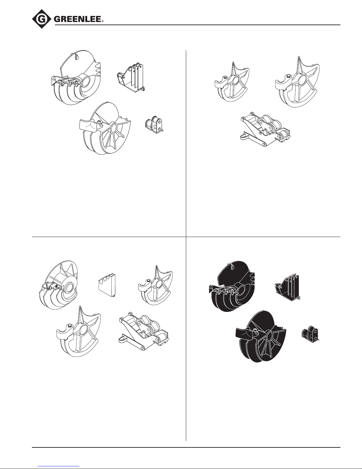
28007: 1/2" to 1-1/4" IMC
1/2" to 2" Rigid Steel
1/2" to 2" Schedule 40 Pipe
UPC No.
Key 78-3310- Description
1 00571 Bending shoe for 1/2" to 1-1/4"
2 00936 Roller support unit for 1/2" to 1-1/4"
3 17937 Bending shoe for 1-1/2" to 2"
4 17984 Roller support unit for 1-1/2" to 2"
2
IMC
1
3
26330: 1-1/2" to 2" IMC
UPC No.
Key 78-3310- Description
1 25263 Bending shoe for 1-1/2"
2 25268 Bending shoe for 2"
3 25273 Roller support unit for 1-1/2" to 2"
23818 Storage box
2
EMT
21
4
5
23802: 1/2" to 2" EMT
UPC No.
Key 78-3310- Description
1 17944 Bending shoe for 1/2" to 1-1/4"
2 17986 Roller support unit for 1/2" to 1-1/4"
3 23499 Bending shoe for 1-1/2"
4 23505 Bending shoe for 2"
5 23541 Roller support unit for 1-1/2" to 2"
23818 Storage box
3
PVC-COATED RIGID
1
34
37279: 1-1/2" to 2" 40 Mil PVC-Coated Rigid
UPC No.
Key 78-3310- Description
1 00573 Bending shoe for 1/2" to 1-1/4"
2 00946 Roller support unit for 1/2" to 1-1/4"
3 37281 Bending shoe for 1-1/2" to 2"
4 37282 Roller support unit for 1-1/2" to 2"
23818 Storage box
2
Greenlee / A Textron Company 7 4455 Boeing Dr. • Rockford, IL 61109-2988 USA • 815-397-7070
Page 8
Setup
555®-22 Electric Bender
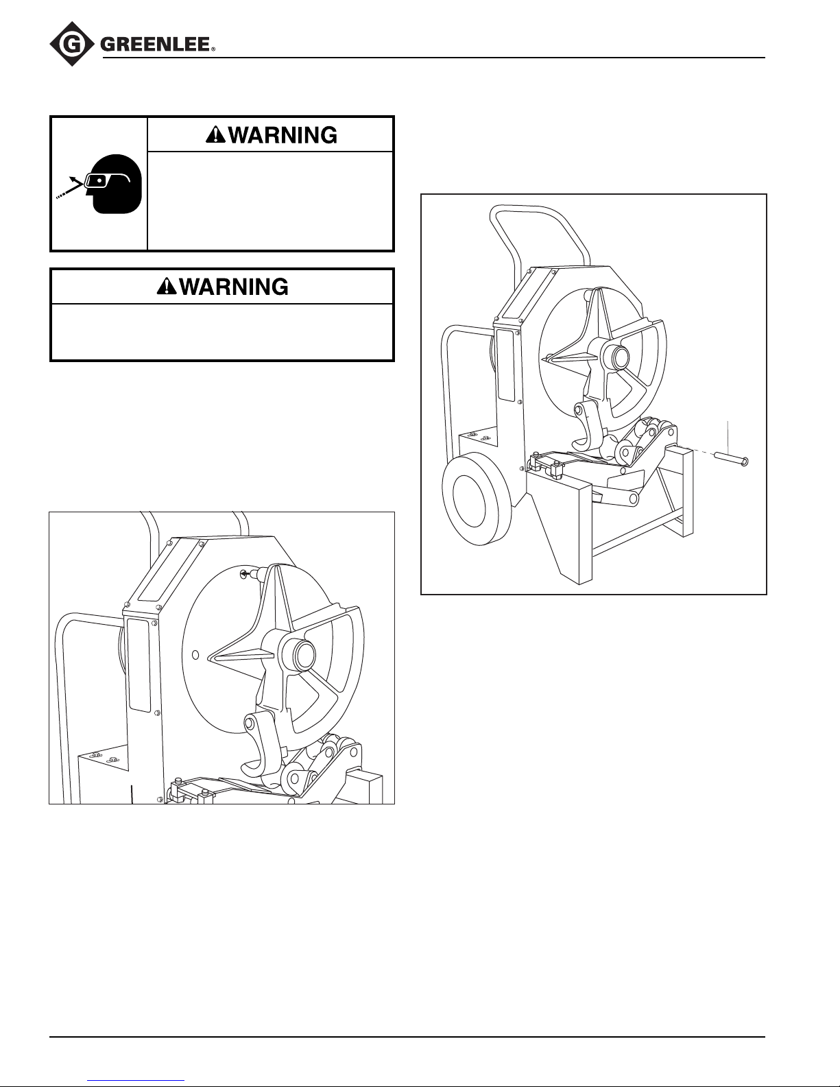
2. Mount the appropriate support unit onto the leg of
the bender and install the hinge pin, as shown.
Wear eye protection when operating
or servicing this tool.
Failure to wear eye protection could
result in serious eye injury from
flying debris.
Unplug the bender before changing accessories.
Accidental startup could result in serious injury.
1. Slide the appropriate bending shoe onto the shaft of
the main sprocket, as shown. Align the four drive
studs on the back of the shoe with the four holes in
the main sprocket.
Note: 1-1/2" and 2" EMT and IMC bending shoes
have only three drive studs.
Installing a Bending Shoe
Roller Support Unit Installed
Install pin
3. Mark the conduit. See the decals on the bender or
the Additional Bending Instructions section of this
manual.
4. Place the bender in either the vertical or horizontal
bending position.
Greenlee / A Textron Company 8 4455 Boeing Dr. • Rockford, IL 61109-2988 USA • 815-397-7070
Page 9
Operation
Wear eye protection when operating
or servicing this tool.
Failure to wear eye protection could
result in serious eye injury from
flying debris.
Pinch points:
Keep hands away from bending
shoe, rollers and conduit when
bender is in use.
Failure to observe this warning could
result in severe injury or death.
555®-22 Electric Bender
BENDING CONDUIT
1. Plug the cord into an appropriate receptacle. See
Grounding Instructions.
2. Press BEND or UNLOAD until the shoe is 5° to 10°
before the 0° starting point.
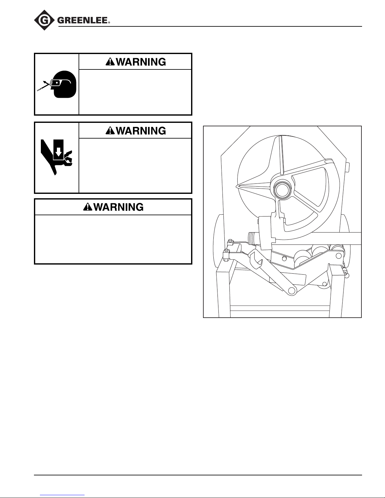
3. Load the conduit so that the bending mark is aligned
with the front edge of the shoe hook, as illustrated.
Loading the Conduit
Do not operate the bender while wearing loose
clothing. Loose clothing can get caught in moving
parts.
Failure to observe this warning could result in
severe injury or death.
4. See the instruction decal for the appropriate bend
angle.
Greenlee / A Textron Company 9 4455 Boeing Dr. • Rockford, IL 61109-2988 USA • 815-397-7070
Page 10
Operation (cont’d)
555®-22 Electric Bender
5. Bend the conduit:
If bending 1-1/2" to 2" EMT or IMC:
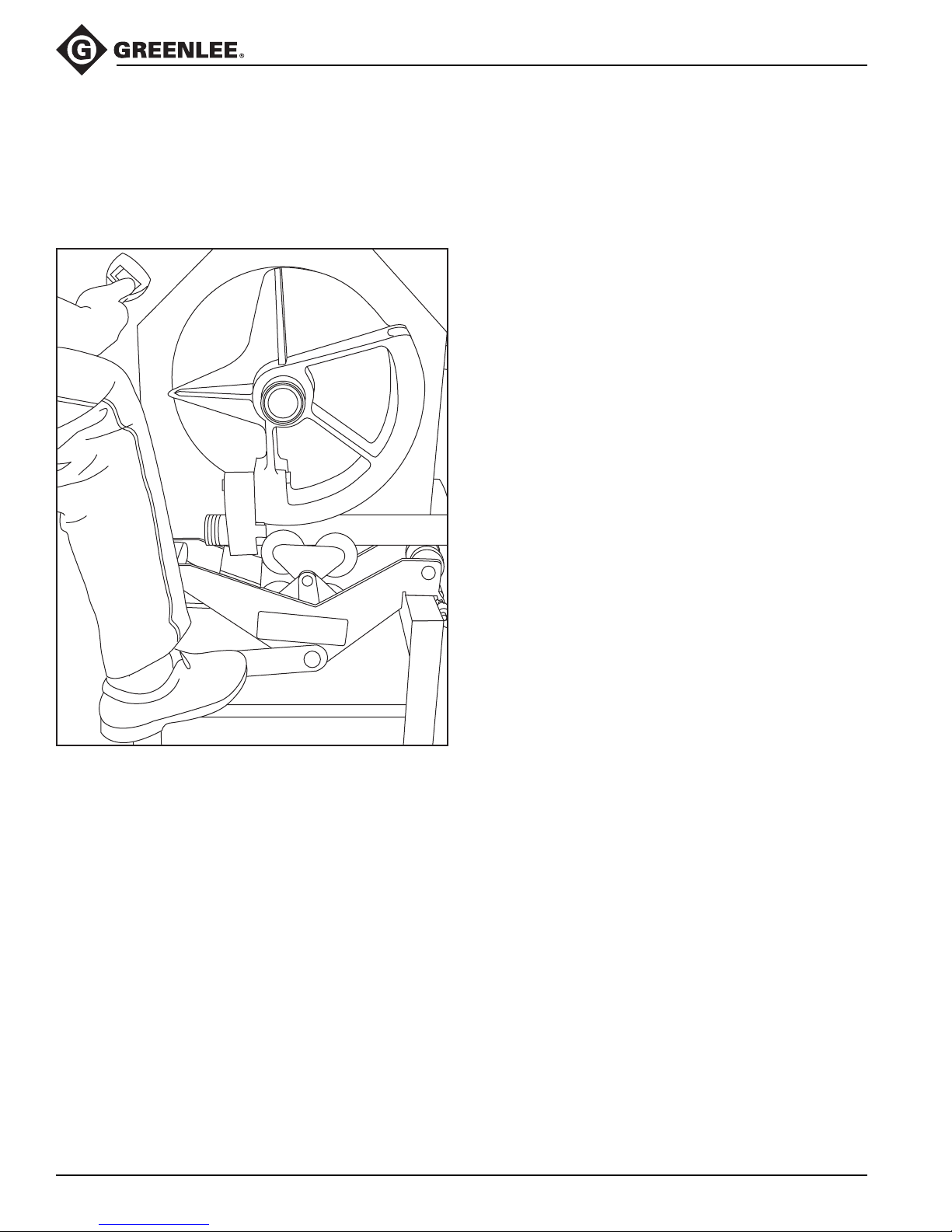
a. Place one foot on the loading pedal, as shown.
Engaging the Loading Pedal
(for 1-1/2" to 2" EMT or IMC Only)
If bending any other size or type of conduit:
a. Press and hold BEND.
b. Release the switch as you approach the desired
angle of bend.
c. Press BEND momentarily until the bend is
complete.
6. Press UNLOAD. The shoe will rotate backward.
Note: If bending EMT or IMC, the roller support unit
will drop to its original position.
7. Twist the conduit to release it from the hook. Remove the conduit.
8. Press and hold UNLOAD until the shoe has rotated
back to 0°.
b. Press and hold BEND. The bender will pull up
the roller support. When the roller support
contacts the stop, remove your foot from the
loading pedal.
c. Release the switch as you approach the desired
angle of bend.
d. Press BEND momentarily until the bend is
complete.
Greenlee / A Textron Company 10 4455 Boeing Dr. • Rockford, IL 61109-2988 USA • 815-397-7070
Page 11
Operation (cont’d)
555®-22 Electric Bender
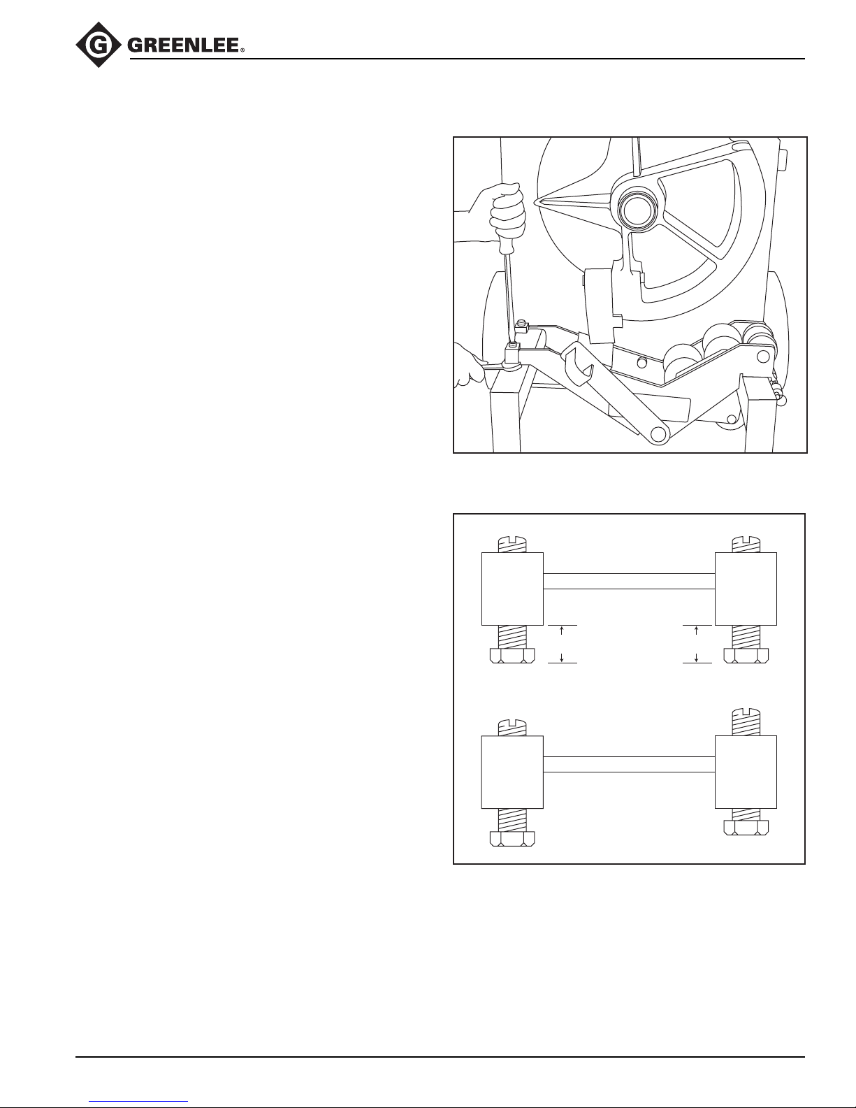
ADJUSTING THE SQUEEZE
When bending 1-1/2" to 2" EMT or IMC, the roller
support must be engaged so that it contacts the conduit;
the pressure against the conduit is the “squeeze.”
Due to variations in conduit, the standard adjustment
may provide too much or too little squeeze. If the conduit
develops excessive side marking when bent, the
squeeze is set too high. If the conduit becomes excessively oval or wrinkled, the squeeze is set too low.
1. Use a screwdriver to loosen the set screws.
2. Use a wrench to rotate both adjusting bolts 1/2 turn
clockwise to INCREASE squeeze or 1/2 turn counterclockwise to DECREASE squeeze.
Note: In order to distribute the load evenly, adjust
both bolts to the same setting. See the illustration.
3. Tighten the set screws.
Adjusting the Squeeze
Standard Squeeze Setting
Adjusting bolts are
at the same setting.
5/8" 5/8"
Adjusting bolts are
at different settings.
INCORRECT
Greenlee / A Textron Company 11 4455 Boeing Dr. • Rockford, IL 61109-2988 USA • 815-397-7070
Page 12
Illustrated Bending Glossary
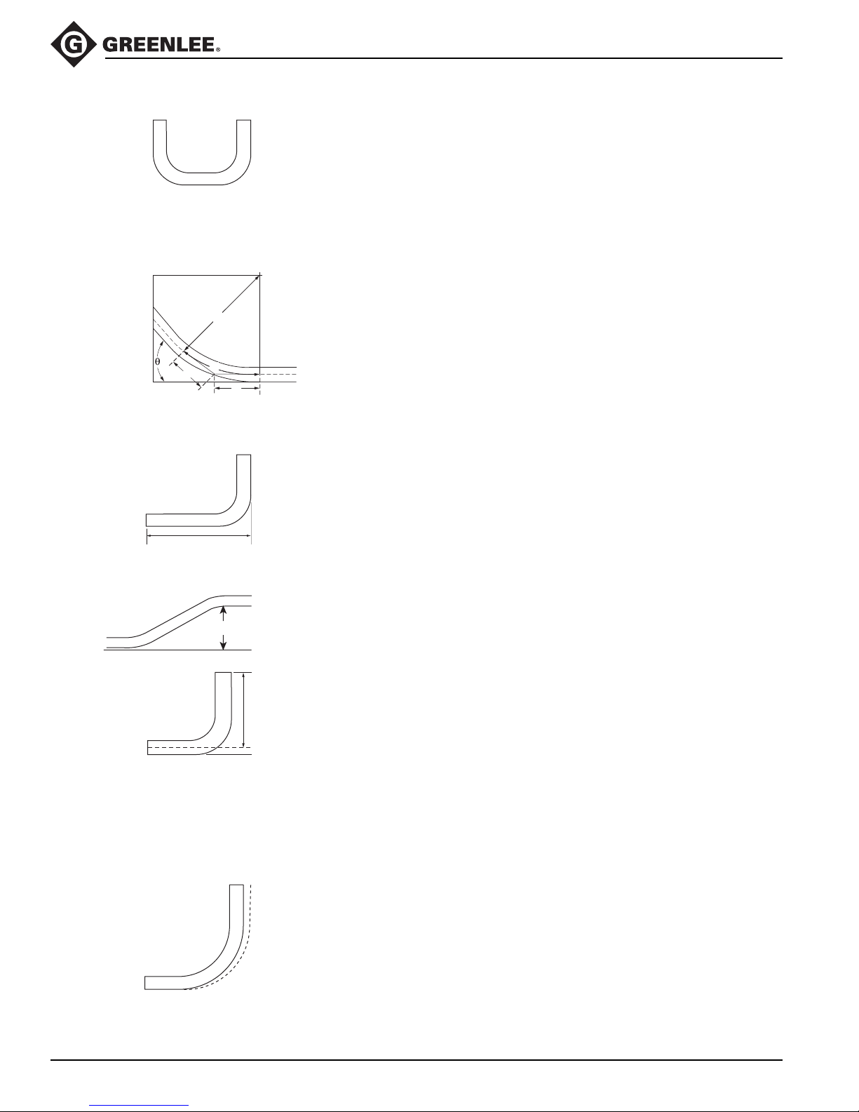
back-to-back bend — any U-shaped bend formed by two
parallel 90° bends with a straight section of conduit or pipe
between the bends.
center-to-center distance — the distance between the
successive bends that make up an offset or a three-bend
saddle.
developed length — the actual length of pipe that will be
bent; see distance “d” in the illustration at left.
555®-22 Electric Bender
r
d
a
Offset Height
gain — the difference between the straight-line distance
(a + a) and the shorter radial distance, (d) where:
θ = angle of bend
a
r = the centerline bending radius of the bending shoe
kick — single bend of less than 90°
leg length — the distance from the end of a straight
section of conduit or pipe to the bend; measured from the
end to the outside edge of the conduit or pipe.
offset bend — two opposite bends with the same degree
of bend; used to avoid an obstruction.
offset height — the distance between the two legs of
an offset bend, measured perpendicular to the two legs;
also called amount of offset and depth of offset.
rise — the distance from the end of a straight section of
conduit or pipe to the bend; measured from the end to the
center line of the conduit or pipe. Also called stub or
stub-up.
saddle — a three-bend or four-bend combination; used
to avoid an obstruction.
shrink — the amount of conduit “lost” when laying out
an offset bend working toward an obstruction; see the
explanation under Offset Bending in this manual.
springback — the amount, measured in degrees, that a
conduit or pipe tends to straighten after being bent.
Greenlee / A Textron Company 12 4455 Boeing Dr. • Rockford, IL 61109-2988 USA • 815-397-7070
Page 13
Bending Instructions
555®-22 Electric Bender
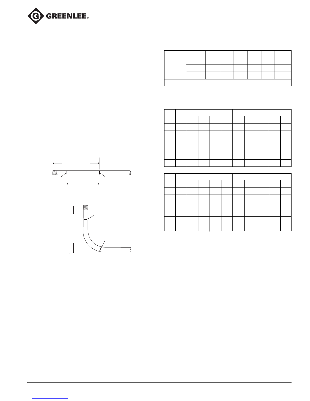
90° STUBS
1. Measure the length of the required stub.
2. See the Minimum Stub Length formula on the
Deduct Table. The required stub must be equal to
or longer than the Minimum Stub Length.
3. Measure and mark the stub length on the conduit.
This is Mark 1. Subtract the Deduct from this mark
and make a new mark. This is Mark 2.
4. Align Mark 2 with the front edge of the hook and
bend the conduit.
Notes:
When the operator presses “UNLOAD”, the conduit may
spring back a few degrees. Compensate by overbending
as shown in the Scale Reading Table.
°
The rigid shoe can make a 180
All other shoes bend to 90
STUB LENGTH
MARK 2
DEDUCT
STUB LENG
TH
bend in one shot.
°
maximum.
MARK 1
MARK 2
MARK 1
Deduct Table
SIZE 1/2 3/4 1 1-1/4 1-1/2 2
RIGID/PVC 7-1/2 9 11 14 14-1/4 16-1/8
DEDUCT EMT 7 8-7/8 10-3/4 13-1/8 13-7/8 15-3/8
IMC 7-1/2 9 11 14 13-3/4 15-1/4
MINIMUM STUB LENGTH = DEDUCT PLUS 2 INCHES
Figures are approximate
Scale Reading Table
RIGID EMT
SIZE
15° 30° 45° 60° 90° 15° 30° 45° 60° 90°
1/2 18-3/4 35 50 66-1/4 96-1/4 16-1/4 32-1/2 47-1/2 63-3/4 95
3/4 17-1/2 32-1/2 47-1/2 63-3/4 95 17-1/2 33-3/4 48-3/4 63-3/4 95
1 17-1/2 33-3/4 48-3/4 65 95 17-1/2 32-1/2 48-3/4 65 95
1-1/4 18-3/4 33-3/4 48-3/4 63-3/4 95 17-1/2 33-3/4 48-3/4 65 95
1-1/2 18-3/4 33-3/4 48-3/4 65 95 16-1/4 31-1/4 46-1/4 61-1/4 92-1/2
2203548-3/4 63-3/4 96-1/4 17-1/2 33-3/4 48-3/4 63-3/4 95
IMC PVC-Coated
15° 30° 45° 60° 90° 15° 30° 45° 60° 90°
SIZE
1/2 20 36-1/4 51-1/4 67-1/2 98-3/4 17-1/2 33-3/4 48-3/4 65 95
3/4 20 36-1/4 51-1/4 67-1/2 97-1/2 17-1/2 33-3/4 48-3/4 63-3/4 95
1 21-1/4 36-1/4 51-1/4 66-1/4 97-1/2 17-1/2 32-1/2 47-1/2 63-3/4 95
1-1/4 18-3/4 33-3/4 50 65 96-1/4 18-3/4 33-3/4 50 65 95
1-1/2 17-1/2 33-3/4 48-3/4 63-3/4 95 18-3/4 33-3/4 48-3/4 65 95
22035506596-1/4 20 35 48-3/4 63-3/4 96-1/4
Figures are approximate
Greenlee / A Textron Company 13 4455 Boeing Dr. • Rockford, IL 61109-2988 USA • 815-397-7070
Page 14
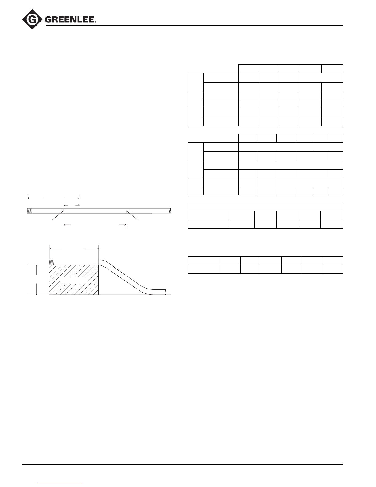
Bending Instructions (cont’d)
555®-22 Electric Bender
Offsets
1. Measure the height and length of the obstruction.
Select the angle to be used.
2. See the Offset Table. The height of the obstruction
must be equal to or greater than the minimum offset.
3. Refer to the X Table to find the X dimension. Refer
to the Offset Table to find the center-to-center
distance.
Note: If the center-to-center distance is not shown,
calculate it by using the multipliers shown in the
Offset Table.
4. Mark the conduit as shown.
5. Insert the conduit into the bender. Align Mark 1 with
the front edge of the hook and bend the conduit.
6. Align Mark 2 with the front edge of the hook. Without
removing the conduit from the bender, rotate the
conduit 180°. Make the second bend.
LENGTH
X
MARK 1
CENTER TO CENTER
DISTANCE
MARK 2
Offset Table
OFFSET ➤ 24 6 8 10
Max Conduit Size 3/4 1-1/2 2 2
15°
Center-to-Center 7-3/4 15-7/16 23-3/16 30-15/16 38-5/8
Max Conduit Size 3/4 1 1-1/2 2
30°
Center-to-Center 8 12 16 20
Max Conduit Size 1/2 1 1-1/4
45°
Center-to-Center 8-1/2 11-5/16 14-1/8
OFFSET ➤ 12 14 16 18 20 22
Max Conduit Size 2
15°
Center-to-Center 46-3/8 54-1/16 61-13/16 69-9/16 77-1/4 85
Max Conduit Size 2
30°
Center-to-Center 24 28 32 36 40 44
Max Conduit Size 1-1/2 2 2
45°
Center-to-Center 16-15/16 19-13/16 22-5/8 25-7/16 28-1/4 31-1/8
CENTER-TO-CENTER DISTANCE = OFFSET HEIGHT x MULTIPLIER
OFFSET ANGLE 10° 15° 22-1/2° 30° 45°
MULTIPLIER 5.8 3.9 2.6 2.0 1.4
Figures are approximate
HEIGHT
LENGTH
OBSTRUCTION
X Table
CONDUIT SIZE 1/2 3/4 1 1-1/4 1-1/2 2
“X” 3-1/16 3-1/16 3-3/16 4 4-1/4 4-1/2
Figures are approximate
Greenlee / A Textron Company 14 4455 Boeing Dr. • Rockford, IL 61109-2988 USA • 815-397-7070
Page 15
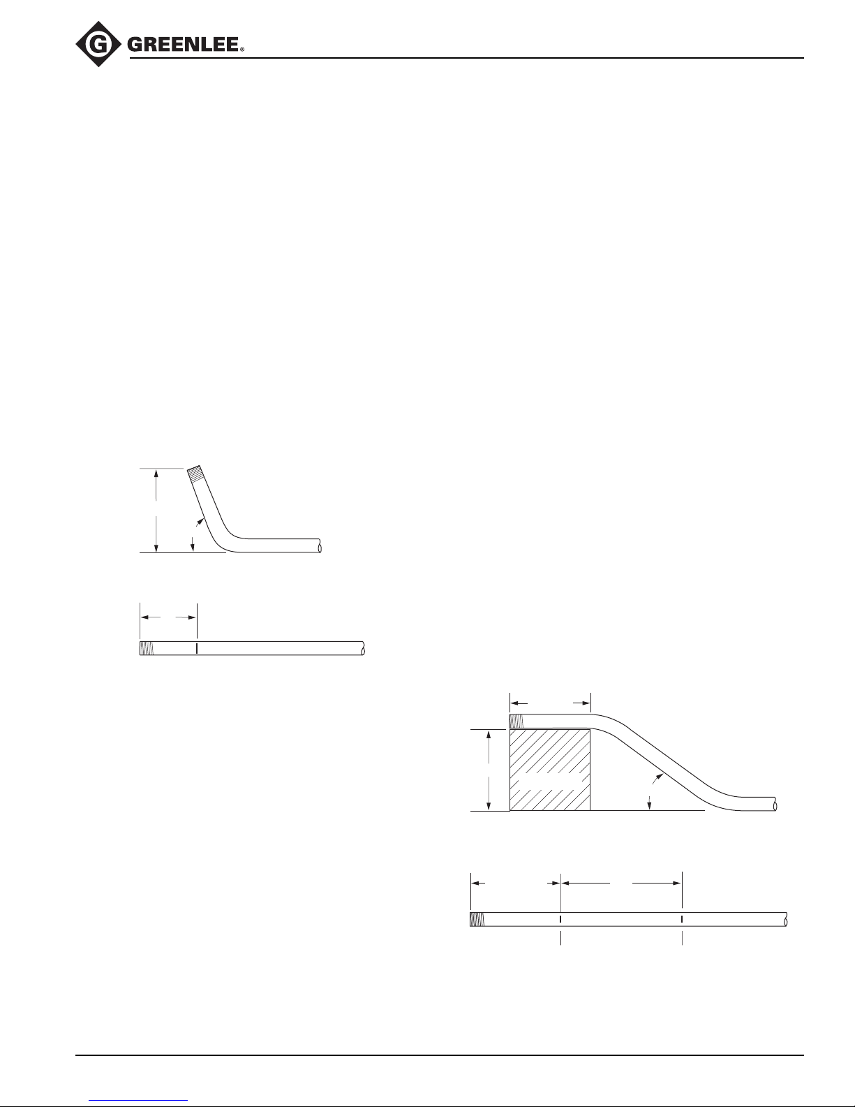
Additional Bending Instructions
555®-22 Electric Bender
The following drawings and bending tables are intended
to provide the information necessary to accomplish the
most common types of bends. The Bending Tables
contain conduit marking information.
STUBS
1. Select the size and type of conduit. Determine the
height of stub and the angle to be used.
2. Find the table that corresponds to the size and type
of conduit selected in Step 1.
3. Under the column labeled ANGLE, find the appropri-
ate angle.
4. Find the row labeled Y. In the row at the top of the
page, find the height (H) of the stub. The number
shown at the intersection of row Y and column H is
the distance Y. Place the bending mark Y inches
from the end of the conduit.
5. Bend the conduit.
HEIGHT
ANGLE
Y
OFFSETS
An offset is used to route the conduit around an obstruction. To make an offset, two equal bends are required.
The distance between the two bends is the center-tocenter distance.
When working past an obstruction, it is necessary to
determine the location of the first bend. The center-tocenter distance is then used to determine the location of
the second bend. When working toward an obstruction,
it is necessary to determine the location of the second
bend. The center-to-center distance is then used to
determine the location of the first bend.
Working Past an Obstruction
1. Select the size and type of conduit. Measure the
height of the obstruction and the distance labeled
LENGTH. Determine the angle to be used.
2. Find the table that corresponds to the size and type
of conduit selected in Step 1.
3. To the right of the size and type of conduit, find the
dimension labeled X. Subtract X from LENGTH.
Place the first bending mark this distance from the
end of the conduit.
4. Under the column labeled ANGLE, find the appropriate angle. Find the row labeled L1. In the row at the
top of the page, find the height (H) of the offset. The
number shown at the intersection of row L1 and
column H is L1. Place the second bending mark L1
inches from the first bending mark.
5. Bend the conduit.
LENGTH
MARK 1
START OF
FIRST
BEND
ANGLE
L1LENGTH – X
MARK 2
MARK
HEIGHT
OBSTRUCTION
Greenlee / A Textron Company 15 4455 Boeing Dr. • Rockford, IL 61109-2988 USA • 815-397-7070
Page 16
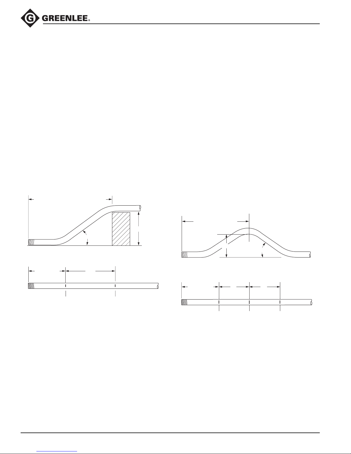
Additional Bending Instructions (cont’d)
555®-22 Electric Bender
Working Toward an Obstruction
1. Select the size and type of conduit. Measure the
height of the obstruction and the distance labeled
LENGTH TO END OF SECOND BEND. Determine
the angle to be used.
2. Find the table that corresponds to the size and type
of conduit selected in Step 1.
3. Under the column labeled ANGLE, find the appropriate angle. Find the row labeled Z. In the row at the
top of the page, find the height (H) of the offset. The
number shown at the intersection of the Z row and
the H column is Z. Subtract Z from LENGTH TO
THE END OF SECOND BEND. Place the first
bending mark this distance from the end of the
conduit.
4. In the same column, find the row labeled L1. Place
the second bending mark L1 inches from the first
bending mark.
5. Bend the conduit.
LENGTH TO END OF SECOND BEND
THREE-BEND SADDLE
1. Select the size and type of conduit. Measure the
height of the obstruction and the distance from the
end of the conduit to the center (LENGTH TO
CENTER) of the bend. Determine the angle to be
used.
2. Find the table that corresponds to the size and type
of conduit selected in Step 1.
3. Under the column labeled ANGLE, find the appropriate angle. Find the row labeled Z. In the row at the
top of the page, find the height (H) of the offset. The
number shown at the intersection of the Z row and
the appropriate H column is Z. Subtract Z from the
LENGTH TO CENTER. Place the first bending mark
this distance from the end of the conduit.
4. In the same column, find the row labeled L1. Place
the second bending mark L1 inches from the first
bending mark.
5. In the same column, find the row labeled L2. Place
the third bending mark L2 inches from the second
bending mark.
6. Bend the conduit.
MARK 1
ANGLE
L1LENGTH – Z
MARK 2
HEIGHT
LENGTH TO CENTER
HEIGHT
MARK 1
L1LENGTH – Z
MARK 2
ANGLE
L2
MARK 3
Greenlee / A Textron Company 16 4455 Boeing Dr. • Rockford, IL 61109-2988 USA • 815-397-7070
Page 17
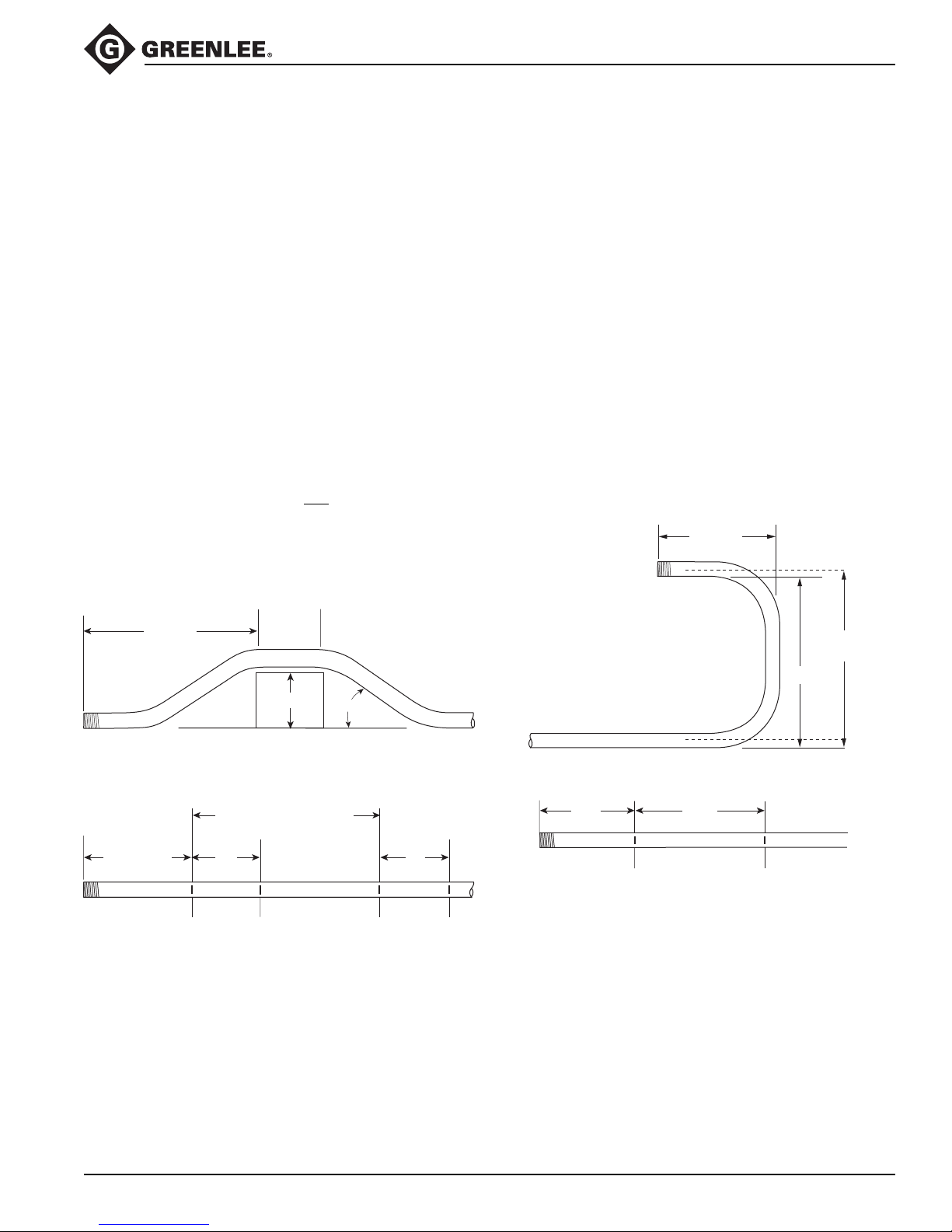
Additional Bending Instructions (cont’d)
555®-22 Electric Bender
FOUR-BEND SADDLE
1. Select the size and type of conduit. Measure the
height of the obstruction, the distance labeled
LENGTH, and the distance labeled STRAIGHT
SECTION. Determine the angle to be used.
2. Find the table that corresponds to the size and type
of conduit selected in Step 1.
3. Under the column labeled ANGLE, find the appropriate angle. Find the row labeled Z. In the row at the
top of the page, find the height (H) of the offset. The
number shown at the intersection of the Z row and
the appropriate H column is Z. Subtract Z from the
LENGTH. Place the first bending mark this distance
from the end of the conduit.
4. In the same column, find the row labeled L1. Place
the second bending mark L1 inches from the first
bending mark.
5. In the same column, find the row labeled L2. Add L2
to the STRAIGHT SECTION. Place the third bending
mark this distance from the
first bending mark.
6. Make the final bending mark L1 inches from the third
bending mark.
7. Bend the conduit.
U-BENDS
1. Select the size and type of conduit. Determine the
LENGTH and the HEIGHT.
2. Find the table that corresponds to the size and type
of conduit selected in Step 1.
3. Under the column labeled ANGLE, find 90°.
4. Find the row labeled Y. In the row at the top of the
page, find the height (H) that corresponds to the
LENGTH. The number shown at the intersection of
the Y row and the appropriate H column is the
distance Y. Place the bending mark Y inches from
the end of the conduit.
5. Find the row labeled L1, and go to the right to find
the height (H) that corresponds to the HEIGHT.
6. The number shown at the intersection of the L1 row
and the appropriate H column is L1. Place the
second bending mark L1 inches from the first mark.
7. Bend the conduit.
LENGTH
LENGTH
LENGTH – Z
MARK 1
STRAIGHT
SECTION
HEIGHT
L2 + STRAIGHT SECTION
L1 L1
MARK 2 MARK 3
ANGLE
MARK 4
HEIGHT
@ ???
HEIGHT
Y
MARK 1
L1
MARK 2
Greenlee / A Textron Company 17 4455 Boeing Dr. • Rockford, IL 61109-2988 USA • 815-397-7070
Page 18

Additional Bending Tables
DIM ANGLE 2" 4" 6" 8" 10" 12" 15" 18" 24" 36"
1/2" EMT
Y15 3.74 11.47 19.20 26.92 34.65 42.38 53.97 65.56 88.74 135.11
L1 15 7.72 15.45 23.18 30.90 38.63 46.36 57.95 69.54 92.72 139.09
L2 15 8.94 16.66 24.39 32.12 39.84 47.57 59.16 70.75 93.94 140.30
Z15 10.70 18.16 25.62 33.09 40.55 48.02 59.21 70.41 92.80 137.59
MINIMUM H = 0.84
Y 22.5 1.37 6.60 11.82 17.05 22.28 27.50 35.34 43.18 58.86 90.22
L1 22.5 5.20 10.43 15.65 20.88 26.11 31.33 39.17 47.01 62.69 94.05
L2 22.5 7.02 12.25 17.48 22.70 27.93 33.16 41.00 48.83 64.51 95.87
Z 22.5 8.68 13.51 18.34 23.17 28.00 32.83 40.07 47.31 61.80 90.77
MINIMUM H = 1.48
Y30 0.04 4.04 8.04 12.04 16.04 20.04 26.04 32.04 44.04 68.04
L1 30 7.94 11.94 15.94 19.94 23.94 29.94 35.94 47.94 71.94
L2 30 10.37 14.37 18.37 22.37 26.37 32.37 38.37 50.37 74.37
Z30 11.42 14.89 18.35 21.82 25.28 30.48 35.67 46.07 66.85
MINIMUM H = 2.25
Y45 1.23 4.05 6.88 9.71 12.54 16.78 21.02 29.51 46.48
L1 45 8.29 11.11 13.94 16.77 21.01 25.26 33.74 50.71
L2 45 11.93 14.76 17.59 20.42 24.66 28.90 37.39 54.36
Z45 11.85 13.85 15.85 17.85 20.85 23.85 29.85 41.85
MINIMUM H = 4.14
Y60 1.83 4.14 6.45 8.76 12.22 15.69 22.62 36.47
L1 60 8.74 11.05 13.36 16.82 20.29 27.21 41.07
L2 60 13.60 15.91 18.22 21.68 25.14 32.07 45.93
Z60 11.99 13.14 14.30 16.03 17.76 21.22 28.15
MINIMUM H = 6.38
Y90 1.00 3.00 5.00 8.00 11.00 17.00 29.00
L1 90 10.01 13.01 16.01 22.01 34.01
L2 90 17.30 20.30 23.30 29.30 41.30
Z90 11.29 11.29 11.29 11.29 11.29
MINIMUM H = 11.29
555®-22 Electric Bender
3/4" EMT
MINIMUM H = 1.12
MINIMUM H = 1.94
MINIMUM H = 2.92
MINIMUM H = 5.27
MINIMUM H = 8.03
MINIMUM H = 13.95
Y15 2.35 10.07 17.80 25.53 33.26 40.98 52.58 64.17 87.35 133.71
L1 15 7.72 15.45 23.17 30.90 38.63 46.36 57.95 69.54 92.72 139.08
L2 15 9.17 16.90 24.62 32.35 40.08 47.81 59.40 70.99 94.17 140.54
Z15 11.79 19.26 26.72 34.19 41.65 49.11 60.31 71.51 93.90 138.68
Y 22.5 0.05 5.28 10.50 15.73 20.95 26.18 34.02 41.86 57.54 88.90
L1 22.5 5.20 10.42 15.65 20.88 26.10 31.33 39.17 47.01 62.69 94.04
L2 22.5 7.37 12.60 17.83 23.05 28.28 33.50 41.34 49.18 64.86 96.22
Z 22.5 9.90 14.73 19.56 24.39 29.22 34.04 41.29 48.53 63.02 91.99
Y30 2.72 6.72 10.72 14.72 18.72 24.72 30.72 42.72 66.72
L1 30 7.93 11.93 15.93 19.93 23.93 29.93 35.93 47.93 71.93
L2 30 10.83 14.83 18.83 22.83 26.83 32.83 38.83 50.83 74.83
Z30 12.77 16.23 19.70 23.16 26.62 31.82 37.02 47.41 68.19
Y45 2.67 5.50 8.33 11.15 15.40 19.64 28.12 45.09
L1 45 8.25 11.08 13.90 16.73 20.97 25.22 33.70 50.67
L2 45 12.60 15.43 18.25 21.08 25.33 29.57 38.05 55.02
Z45 13.46 15.46 17.46 19.46 22.46 25.46 31.46 43.46
Y60 0.33 2.64 4.95 7.26 10.72 14.18 21.11 34.97
L1 60 10.95 13.26 16.72 20.19 27.12 40.97
L2 60 16.75 19.06 22.53 25.99 32.92 46.78
Z60 15.04 16.20 17.93 19.66 23.12 30.05
Y90 1.13 3.13 6.13 9.13 15.13 27.13
L1 90 12.62 15.62 21.62 33.62
L2 90 21.32 24.32 30.32 42.32
Z90 13.95 13.95 13.95 13.95
Greenlee / A Textron Company 18 4455 Boeing Dr. • Rockford, IL 61109-2988 USA • 815-397-7070
Page 19

Additional Bending Tables (cont’d)
DIM ANGLE 2" 4" 6" 8" 10" 12" 15" 18" 24" 36"
1" EMT
Y15 1.35 9.07 16.80 24.53 32.26 39.98 51.57 63.16 86.35 132.71
L1 15 7.72 15.44 23.17 30.90 38.63 46.35 57.95 69.54 92.72 139.08
L2 15 9.54 17.26 24.99 32.72 40.45 48.17 59.76 71.36 94.54 140.90
Z15 12.51 19.98 27.44 34.91 42.37 49.83 61.03 72.23 94.62 139.40
MINIMUM H = 1.31
Y 22.5 4.33 9.56 14.78 20.01 25.24 33.07 40.91 56.59 87.95
L1 22.5 10.42 15.64 20.87 26.10 31.32 39.16 47.00 62.68 94.04
L2 22.5 13.15 18.37 23.60 28.82 34.05 41.89 49.73 65.41 96.77
Z 22.5 15.64 20.47 25.30 30.13 34.96 42.20 49.44 63.93 92.90
MINIMUM H = 2.29
Y30 1.75 5.75 9.75 13.75 17.75 23.75 29.75 41.75 65.75
L30 7.91 11.91 15.91 19.91 23.91 29.91 35.91 47.91 71.91
L2 30 11.55 15.55 19.55 23.55 27.55 33.55 39.55 51.55 75.55
Z30 13.87 17.34 20.80 24.27 27.73 32.92 28.12 48.51 69.30
MINIMUM H = 3.47
Y45 1.56 4.39 7.22 10.05 14.29 18.53 27.02 43.99
L1 45 11.01 13.84 16.67 20.91 25.16 33.64 50.61
L2 45 16.47 19.30 22.13 26.37 30.62 39.10 56.07
Z45 16.98 18.98 20.98 23.98 26.98 32.98 44.98
MINIMUM H = 6.35
Y60 1.33 3.64 5.95 9.42 12.88 19.81 33.67
L1 60 10.80 13.11 16.57 20.04 26.97 40.82
L2 60 18.08 20.39 23.85 27.32 34.24 48.10
Z60 17.02 18.17 19.91 21.64 25.10 32.03
MINIMUM H = 9.74
Y90 1.25 4.25 7.25 13.25 25.25
L1 90 15.02 21.02 33.02
L2 90 25.93 31.93 43.93
Z90 17.12 17.12 17.12
MINIMUM H = 17.12
555®-22 Electric Bender
1-1/4" EMT
MINIMUM H = 1.48
MINIMUM H = 2.66
MINIMUM H = 4.09
MINIMUM H = 7.65
MINIMUM H = 11.92
MINIMUM H = 21.38
Y15 0.26 7.99 15.72 23.45 31.17 38.90 50.49 62.08 85.27 131.63
L1 15 7.71 15.44 23.17 30.90 38.62 46.35 57.94 69.53 92.72 139.08
L2 15 10.07 17.80 25.52 33.25 40.98 48.71 60.30 71.89 95.07 141.44
Z15 13.20 20.66 28.12 35.59 43.05 50.52 61.71 72.91 95.30 140.09
Y 22.5 3.33 8.55 13.78 19.01 24.23 32.07 39.91 55.59 86.95
L1 22.5 10.41 15.63 20.86 26.09 31.31 39.15 46.99 62.67 94.03
L2 22.5 13.94 19.17 24.40 29.62 34.85 42.69 50.53 66.21 97.56
Z 22.5 16.60 21.43 26.26 31.09 35.91 43.16 50.40 64.89 93.86
Y30 0.72 4.72 8.72 12.72 16.72 22.72 28.72 40.72 64.72
L1 30 11.89 15.89 19.89 23.89 29.89 35.89 47.89 71.89
L2 30 16.61 20.61 24.61 28.61 34.61 40.61 52.61 76.61
Z30 18.58 22.04 25.51 28.97 34.17 39.37 49.76 70.54
Y45 0.33 3.15 5.98 8.81 13.05 17.30 25.78 42.75
L1 45 10.93 13.75 16.58 20.83 25.07 33.55 50.52
L2 45 18.00 20.83 23.66 27.90 32.14 40.63 57.60
Z45 18.82 20.82 22.82 25.82 28.82 34.82 46.82
Y60 2.11 4.42 7.89 11.35 18.28 32.14
L1 60 12.89 16.35 19.82 26.74 40.60
L2 60 22.32 25.79 29.25 36.18 50.04
Z60 20.69 22.42 24.16 27.62 34.55
Y90 1.88 4.88 10.88 22.88
L1 90 20.13 32.13
L2 90 34.29 46.29
Z90 21.38 21.38
Greenlee / A Textron Company 19 4455 Boeing Dr. • Rockford, IL 61109-2988 USA • 815-397-7070
Page 20

Additional Bending Tables (cont’d)
DIM ANGLE 2" 4" 6" 8" 10" 12" 15" 18" 24" 36"
1-1/2" EMT
Y15 6.26 13.99 21.72 29.44 37.17 48.76 60.35 83.53 129.90
L1 15 7.71 15.44 23.17 30.90 38.62 46.35 57.94 69.53 92.72 139.08
L2 15 9.95 17.68 25.40 33.13 40.86 48.58 60.18 71.77 94.95 141.31
Z15 14.42 21.88 29.35 36.81 44.28 51.74 62.94 74.13 96.53 141.31
MINIMUM H = 1.81
Y 22.5 1.77 7.00 12.22 17.45 22.68 30.52 38.36 54.03 85.39
L1 22.5 10.41 15.64 20.86 26.09 31.31 39.15 46.99 62.67 94.03
L2 22.5 13.76 18.98 24.21 29.44 34.66 42.50 50.34 66.02 97.38
Z 22.5 17.76 22.59 27.42 32.25 37.07 44.32 51.56 66.04 95.02
MINIMUM H = 3.11
Y30 3.26 7.26 11.26 15.26 21.26 27.26 39.26 63.26
L1 30 11.90 15.90 19.90 23.90 29.90 35.90 47.90 71.90
L2 30 16.36 20.36 24.36 28.36 34.36 40.36 52.36 76.36
Z30 19.67 23.14 26.60 30.07 35.26 40.46 50.85 71.64
MINIMUM H = 4.64
Y45 1.84 4.67 7.50 11.74 15.98 24.47 41.44
L1 45 13.78 16.60 20.85 25.09 33.57 50.54
L2 45 20.47 23.30 27.55 31.79 40.27 57.24
Z45 21.78 23.78 26.78 29.78 35.78 47.78
MINIMUM H = 8.33
Y60 0.91 3.22 6.68 10.15 17.07 30.93
L1 60 16.40 19.87 26.80 40.65
L2 60 25.34 28.80 35.73 49.58
Z60 23.22 24.95 28.42 35.34
MINIMUM H = 12.61
Y90 0.89 3.89 9.89 21.89
L1 90 20.34 32.34
L2 90 33.74 45.74
Z90 21.77 21.77
MINIMUM H = 21.77
555®-22 Electric Bender
2" EMT
MINIMUM H = 1.89
MINIMUM H = 3.28
MINIMUM H = 4.94
MINIMUM H = 8.95
MINIMUM H = 13.63
MINIMUM H = 23.74
Y15 5.15 12.87 20.60 28.33 36.05 47.65 59.24 82.42 128.78
L1 15 7.71 15.44 23.17 30.90 38.62 46.35 57.94 69.53 92.71 139.08
L2 15 10.19 17.92 25.64 33.37 41.10 48.83 60.42 72.01 95.19 141.56
Z15 14.77 22.24 29.70 37.17 44.63 52.10 63.29 74.49 96.88 141.66
Y 22.5 0.88 6.11 11.33 16.56 21.79 29.62 37.46 53.14 84.50
L1 22.5 10.40 15.63 20.86 26.08 31.31 39.15 46.99 62.67 94.02
L2 22.5 14.12 19.35 24.57 29.80 35.02 42.86 50.70 66.38 97.74
Z 22.5 18.24 23.07 27.90 32.73 37.55 44.80 52.04 66.52 95.50
Y30 2.45 6.45 10.45 14.45 20.45 26.45 38.45 62.45
L1 30 11.88 15.88 19.88 23.88 29.88 35.88 47.88 71.88
L2 30 16.84 20.84 24.84 28.84 34.84 40.84 52.84 76.84
Z30 20.28 23.75 27.21 30.67 35.87 41.07 51.46 72.24
Y45 1.02 3.85 6.68 10.92 15.16 23.65 40.62
L1 45 13.74 16.56 20.81 25.05 33.53 50.50
L2 45 21.16 23.99 28.24 32.48 40.96 57.93
Z45 22.66 24.66 27.66 30.66 36.66 48.66
Y60 0.00 2.31 5.77 9.23 16.16 30.02
L1 60 16.30 19.77 26.70 40.55
L2 60 26.21 29.67 36.60 50.46
Z60 24.40 26.14 29.60 36.53
Y90 2.62 8.62 20.62
L1 90 19.94 31.94
L2 90 34.80 46.80
Z90 23.74 23.74
Greenlee / A Textron Company 20 4455 Boeing Dr. • Rockford, IL 61109-2988 USA • 815-397-7070
Page 21

Additional Bending Tables (cont’d)
DIM ANGLE 2" 4" 6" 8" 10" 12" 15" 18" 24" 36"
1/2" IMC, Rigid, and 40 Mil PVC-Coated Rigid
Y15 3.03 10.76 18.48 26.21 33.94 41.67 53.26 64.85 88.03 134.39
L1 15 7.72 15.45 23.18 30.90 38.63 46.36 57.95 69.54 92.72 139.09
L2 15 8.87 16.59 24.32 32.05 39.78 47.50 59.10 70.69 93.87 140.23
Z15 11.12 18.58 26.05 33.51 40.97 48.44 59.63 70.83 93.22 138.01
MINIMUM H = 0.95
Y 22.5 .77 5.98 11.21 16.44 21.66 26.89 34.73 42.57 58.25 89.60
L1 22.5 5.20 10.43 15.66 20.88 26.11 31.34 39.17 47.01 62.69 94.05
L2 22.5 6.92 12.15 17.38 22.60 27.83 33.06 40.89 48.73 64.41 95.77
Z 22.5 9.07 13.90 18.73 23.56 28.38 33.21 40.46 47.70 62.18 91.15
MINIMUM H = 1.62
Y30 3.49 7.49 11.49 15.49 19.49 25.49 31.49 43.49 67.49
L1 30 7.95 11.95 15.95 19.95 23.95 29.95 35.95 47.95 71.95
L2 30 10.24 14.24 18.24 22.24 26.24 32.24 38.24 50.24 74.24
Z30 11.78 15.24 18.70 22.17 25.63 30.83 36.02 46.42 67.20
MINIMUM H = 2.42
Y45 3.59 6.41 9.23 12.06 16.30 20.55 29.03 46.00
L1 45 8.30 11.13 13.95 16.78 21.02 25.27 33.75 50.72
L2 45 11.74 14.57 17.39 20.22 24.46 28.71 37.19 54.16
Z45 12.13 14.13 16.13 18.13 21.13 24.13 30.13 42.13
MINIMUM H = 4.33
Y60 1.42 3.73 6.04 8.34 11.81 15.27 22.20 36.06
L1 60 8.77 11.08 13.39 16.85 20.31 27.24 41.10
L2 60 13.35 15.66 17.97 21.44 24.90 31.83 45.69
Z60 12.18 13.33 14.49 16.22 17.95 21.41 28.34
MINIMUM H = 6.55
Y90 .71 2.71 4.71 7.71 10.71 16.70 28.70
L1 90 10.12 13.12 16.12 22.12 34.12
L2 90 17.00 20.00 23.00 29.00 41.00
Z90 11.26 11.26 11.26 11.26 11.26
MINIMUM H = 11.26
555®-22 Electric Bender
3/4" IMC, Rigid, and 40 Mil PVC-Coated Rigid
Y15 1.86 9.58 17.31 25.04 32.77 40.49 52.08 63.68 86.86 133.22
L1 15 7.72 15.45 23.17 30.90 38.63 46.36 57.95 69.54 92.72 139.08
L2 15 9.19 16.91 24.64 32.37 40.09 47.82 59.41 71.00 94.19 140.55
MINIMUM H = 1.19
MINIMUM H = 2.05
MINIMUM H = 3.06
MINIMUM H = 5.49
MINIMUM H = 8.31
MINIMUM H = 14.33
Z15 12.06 19.53 26.89 34.46 41.92 49.38 60.58 71.78 94.17 138.95
Y 22.5 4.85 10.08 15.31 20.53 25.76 33.60 41.44 57.12 88.47
L1 22.5 10.42 15.65 20.88 26.10 31.33 39.17 47.01 62.69 94.04
L2 22.5 12.62 17.85 23.08 28.30 33.53 41.37 49.21 64.89 96.24
Z 22.5 15.01 19.84 24.67 29.49 34.32 41.57 48.81 63.29 92.26
Y30 2.33 6.33 10.33 14.33 18.33 24.33 30.33 42.33 66.33
L1 30 7.93 11.93 15.93 19.93 23.93 29.93 35.93 47.93 71.93
L2 30 10.86 14.86 18.86 22.86 26.86 32.86 38.86 50.86 74.86
Z30 13.05 16.52 19.98 23.45 26.91 32.11 37.30 47.70 68.48
Y45 2.31 5.13 7.96 10.79 15.03 19.28 27.76 44.73
L1 45 8.24 11.07 13.90 16.73 20.97 25.21 33.70 50.67
L2 45 12.64 15.47 18.30 21.13 25.37 29.61 38.10 55.07
Z45 13.76 15.76 17.76 19.76 22.76 25.76 31.76 43.76
Y60 2.28 4.59 6.90 10.36 13.83 20.75 34.61
L1 60 10.94 13.25 16.72 20.18 27.11 40.97
L2 60 16.81 19.12 22.58 26.05 32.98 46.83
Z60 15.36 16.52 18.25 19.88 23.45 30.38
Y90 .76 2.76 5.76 8.76 14.76 26.76
L1 90 12.60 15.60 21.60 33.60
L2 90 21.39 24.39 30.39 42.39
Z90 14.33 14.33 14.33 14.33
Greenlee / A Textron Company 21 4455 Boeing Dr. • Rockford, IL 61109-2988 USA • 815-397-7070
Page 22

Additional Bending Tables (cont’d)
DIM ANGLE 2" 4" 6" 8" 10" 12" 15" 18" 24" 36"
1" IMC, Rigid, and 40 Mil PVC-Coated Rigid
Y15 1.08 8.81 16.52 24.25 31.97 39.70 51.29 62.88 86.07 132.43
L1 15 7.72 15.44 23.17 30.90 38.63 46.35 57.94 69.54 92.72 139.08
L2 15 9.59 17.32 25.04 32.77 40.50 48.23 59.82 71.41 94.59 140.95
Z15 12.53 20.00 27.46 34.93 42.39 49.86 61.05 72.25 94.64 139.43
MINIMUM H = 1.31
Y 22.5 4.13 9.35 14.58 19.81 25.03 32.87 40.71 56.39 87.75
L1 22.5 10.42 15.64 20.87 26.09 31.32 39.16 47.00 62.68 94.04
L2 22.5 13.22 18.45 23.68 28.90 34.13 41.97 49.81 65.49 96.84
Z 22.5 15.69 20.52 25.35 30.18 35.01 42.25 49.49 63.98 92.95
MINIMUM H = 2.31
Y30 1.58 5.58 9.58 13.58 17.58 23.58 29.58 41.58 65.58
L1 30 7.91 11.91 15.91 19.91 23.91 29.91 35.91 47.91 71.91
L2 30 11.66 15.66 19.66 23.66 27.66 33.66 39.66 51.66 75.66
Z30 13.95 17.41 20.88 24.34 27.81 33.00 38.20 48.59 69.38
MINIMUM H = 3.51
Y45 1.42 4.24 7.06 9.89 14.14 18.38 26.86 43.83
L1 45 11.01 13.83 16.66 20.91 25.15 33.63 50.60
L2 45 16.62 19.45 22.28 26.52 30.76 39.25 56.22
Z45 17.11 19.11 21.11 24.11 27.11 33.11 45.11
MINIMUM H = 6.44
Y60 1.17 3.48 5.79 9.25 12.71 19.64 33.49
L1 60 10.78 13.09 16.55 20.02 26.94 40.80
L2 60 18.27 20.58 24.04 27.50 34.43 48.29
Z60 17.22 18.37 20.11 21.84 25.30 32.23
MINIMUM H = 9.91
Y90 1.01 4.01 7.01 13.01 25.01
L1 90 14.93 20.93 32.93
L2 90 26.16 32.16 44.16
Z90 17.49 17.49 17.49
MINIMUM H = 17.49
555®-22 Electric Bender
1-1/4" IMC, Rigid, and 40 Mil PVC-Coated Rigid
Y15 7.15 14.87 22.60 30.33 38.06 49.65 61.24 84.42 130.78
L1 15 7.71 15.44 23.17 30.90 38.62 46.35 57.94 69.53 92.72 139.08
L2 15 10.07 17.80 25.53 33.25 40.98 48.71 60.30 71.89 95.07 141.44
MINIMUM H = 1.63
MINIMUM H = 2.88
MINIMUM H = 4.38
MINIMUM H = 8.06
MINIMUM H = 11.32
MINIMUM H = 21.96
Z15 13.77 21.24 28.70 36.17 43.63 51.09 62.29 73.49 95.88 140.66
Y 22.5 2.57 7.80 13.02 18.25 23.47 31.31 39.15 54.83 86.19
L1 22.5 10.41 15.63 20.86 26.09 31.31 39.15 46.99 62.67 94.03
L2 22.5 13.94 19.17 24.40 29.62 34.85 42.69 50.53 66.21 97.56
Z 22.5 17.18 22.01 26.84 31.66 36.49 43.73 50.98 65.46 94.43
Y30 4.00 8.00 12.00 16.00 22.00 28.00 40.00 64.00
L1 30 11.89 15.89 19.89 23.89 29.89 35.89 47.89 71.89
L2 30 16.61 20.61 24.61 28.61 34.61 40.61 52.61 76.61
Z30 19.16 22.62 26.09 29.55 34.75 39.94 50.33 71.12
Y45 2.48 5.31 8.14 12.38 16.62 25.11 42.08
L1 45 13.75 16.58 20.83 25.07 33.55 50.52
L2 45 20.83 23.66 27.90 32.14 40.63 57.60
Z45 21.40 23.40 26.40 29.40 35.40 47.40
Y60 1.46 3.77 7.23 10.69 17.62 31.48
L1 60 16.35 19.82 26.74 40.60
L2 60 25.79 29.25 36.18 50.04
Z60 23.00 24.73 28.20 35.13
Y90 1.23 4.23 10.23 22.23
L1 90 20.13 32.13
L2 90 34.29 46.29
Z90 21.96 21.96
Greenlee / A Textron Company 22 4455 Boeing Dr. • Rockford, IL 61109-2988 USA • 815-397-7070
Page 23

Additional Bending Tables (cont’d)
DIM ANGLE 2" 4" 6" 8" 10" 12" 15" 18" 24" 36"
1-1/2" Rigid and 40 Mil PVC-Coated Rigid
Y15 5.87 13.59 21.32 29.05 36.77 48.37 59.96 83.14 129.50
L1 15 7.71 15.44 23.17 20.90 38.62 46.35 57.94 69.53 92.72 139.08
L2 15 9.94 17.67 25.39 33.12 40.85 48.58 60.17 71.76 94.94 141.31
Z15 14.50 21.97 29.43 36.89 44.36 51.82 63.02 74.21 96.61 141.39
MINIMUM H = 1.82
Y 22.5 1.48 6.71 11.93 17.16 22.38 30.22 38.06 53.74 85.10
L1 22.5 10.41 15.64 20.86 26.09 31.31 39.15 46.99 62.67 94.03
L2 22.5 13.75 18.97 24.20 29.43 34.65 42.49 50.33 66.01 97.37
Z 22.5 17.84 22.67 27.50 32.32 37.15 44.39 51.64 66.12 95.09
MINIMUM H = 3.13
Y30 3.02 7.02 11.02 15.02 21.02 27.02 39.02 63.02
L1 30 11.90 15.90 19.90 23.90 29.90 35.90 47.90 71.90
L2 30 16.35 20.35 24.35 28.35 34.35 40.35 52.35 76.35
Z30 19.75 23.21 26.68 30.14 35.34 40.53 50.92 71.71
MINIMUM H = 4.68
Y45 1.65 4.48 7.31 11.55 15.79 24.28 41.25
L1 45 13.78 16.60 20.85 25.09 33.58 50.55
L2 45 20.45 23.28 27.52 31.77 40.25 57.22
Z45 21.84 23.84 26.84 29.84 35.84 47.84
MINIMUM H = 8.37
Y60 0.74 3.05 6.52 9.98 16.91 30.76
L1 60 16.41 19.87 26.80 40.66
L2 60 25.31 28.77 35.70 49.56
Z60 23.28 25.01 28.47 35.40
MINIMUM H = 12.66
Y90 0.75 3.75 9.75 21.75
L1 90 20.35 32.35
L2 90 33.70 45.70
Z90 21.80 21.80
MINIMUM H = 21.80
555®-22 Electric Bender
2" Rigid and 40 Mil PVC-Coated Rigid
Y15 4.42 12.15 19.87 27.60 35.33 46.92 58.51 81.69 128.06
L1 15 7.71 15.44 23.17 30.89 38.62 46.35 57.94 69.53 92.71 139.08
L2 15 10.27 18.00 25.73 33.46 41.18 48.91 60.50 72.09 95.27 141.64
MINIMUM H = 2.00
MINIMUM H = 3.47
MINIMUM H = 5.20
MINIMUM H = 9.38
MINIMUM H = 14.25
MINIMUM H = 24.72
Z15 15.20 22.66 30.13 37.59 45.06 52.52 63.72 74.91 97.30 142.09
Y 22.5 0.24 5.47 10.70 15.92 21.15 28.99 36.83 52.51 83.86
L1 22.5 10.40 15.63 20.85 26.08 31.31 39.15 46.99 62.66 94.02
L2 22.5 14.24 19.47 24.70 29.92 35.15 42.99 50.83 66.51 97.86
Z 22.5 18.71 23.54 28.36 33.19 38.02 45.26 52.51 66.99 95.96
Y30 1.84 5.84 9.84 13.84 19.84 25.84 37.84 61.84
L1 30 11.88 15.88 19.88 23.88 29.88 35.88 47.88 71.88
L2 30 17.00 21.00 25.00 29.00 35.00 41.00 53.00 77.00
Z30 20.79 24.26 27.72 31.19 36.38 41.58 51.97 71.75
Y45 0.42 3.25 6.08 10.32 14.57 23.05 40.02
L1 45 13.72 16.55 20.79 25.04 33.52 50.49
L2 45 21.40 24.23 28.47 32.72 41.20 58.17
Z45 23.26 25.26 28.26 31.26 37.26 49.26
Y60 1.68 5.14 8.61 15.54 29.39
L1 60 16.27 19.73 26.66 40.52
L2 60 26.51 29.97 36.90 50.76
Z60 25.11 26.85 30.31 37.24
Y90 1.87 7.87 19.87
L1 90 31.80
L2 90 47.16
Z90 24.72
Greenlee / A Textron Company 23 4455 Boeing Dr. • Rockford, IL 61109-2988 USA • 815-397-7070
Page 24

Additional Bending Tables (cont’d)
DIM ANGLE 2" 4" 6" 8" 10" 12" 15" 18" 24" 36"
1-1/2" IMC
Y15 6.41 14.14 21.87 29.60 37.32 48.91 60.51 83.69 130.05
L1 15 7.71 15.44 23.17 30.90 38.62 46.35 57.94 69.53 92.72 139.00
L2 15 9.95 17.68 25.40 33.13 40.86 48.58 60.18 71.77 94.94 141.31
Z15 13.99 21.45 28.92 36.38 43.85 51.31 62.51 73.70 96.10 140.88
MINIMUM H = 1.69
Y 22.5 2.02 7.24 12.47 17.69 22.92 30.76 38.60 54.28 85.64
L1 22.5 10.41 15.64 20.86 26.09 31.31 39.15 46.99 62.67 94.03
L2 22.5 13.76 18.98 24.21 29.44 34.66 42.50 50.34 66.02 97.38
Z 22.5 17.33 22.16 26.99 31.82 36.64 43.89 51.13 65.61 94.59
MINIMUM H = 2.94
Y30 3.55 7.55 11.55 15.55 21.55 27.55 39.55 63.55
L1 30 11.90 15.90 19.90 23.90 29.90 35.90 47.90 71.90
L2 30 16.36 20.36 24.36 28.36 34.36 40.36 52.36 76.36
Z30 19.24 22.71 26.17 29.64 34.83 40.03 50.42 71.21
MINIMUM H = 4.43
Y45 2.17 5.00 7.83 12.07 16.31 24.80 41.77
L1 45 13.78 16.60 20.85 25.09 33.57 50.54
L2 45 20.47 23.30 27.55 31.79 40.27 57.24
Z45 21.35 23.35 26.35 29.35 35.35 47.35
MINIMUM H = 8.02
Y60 1.26 3.56 7.03 10.49 17.42 31.28
L1 60 16.40 19.87 26.80 40.65
L2 60 25.34 28.80 35.73 49.58
Z60 22.79 24.52 27.99 34.91
MINIMUM H = 12.24
Y90 1.25 4.25 10.25 22.25
L1 90 20.34 32.34
L2 90 33.74 45.74
Z90 21.34 21.34
MINIMUM H = 21.34
555®-22 Electric Bender
2" IMC
MINIMUM H = 1.84
MINIMUM H = 3.20
MINIMUM H = 4.84
MINIMUM H = 8.80
MINIMUM H = 13.45
MINIMUM H = 23.53
Y15 5.04 12.77 20.50 28.22 35.95 47.54 59.13 82.31 128.68
L1 15 7.71 15.44 23.17 30.90 38.62 46.35 57.94 69.53 92.71 139.00
L2 15 10.19 17.92 25.64 33.37 41.10 48.83 60.42 72.01 95.19 141.56
Z15 14.56 22.03 29.49 36.96 44.42 51.89 63.00 74.28 96.67 141.45
Y 22.5 0.88 6.10 11.33 16.56 21.78 29.62 37.46 53.14 84.50
L1 22.5 10.40 15.63 20.86 26.08 31.31 39.15 46.99 62.67 94.02
L2 22.5 14.12 19.35 24.57 29.80 35.02 42.86 50.70 66.38 97.74
Z 22.5 18.03 22.86 27.69 32.52 37.34 44.59 51.83 66.31 95.29
Y30 2.50 6.50 10.50 14.50 20.50 26.50 38.50 62.50
L1 30 11.88 15.88 19.88 23.88 29.88 35.88 47.88 71.88
L2 30 16.84 20.84 24.84 28.84 34.84 40.84 52.84 76.84
Z30 20.07 23.54 27.00 30.46 35.66 40.86 51.25 72.03
Y45 1.12 3.94 6.77 11.02 15.26 23.74 40.71
L1 45 13.74 16.56 20.81 25.05 33.53 50.50
L2 45 21.16 23.99 28.24 32.48 40.96 57.93
Z45 22.45 24.45 27.45 30.45 36.45 48.45
Y60 0.11 2.42 5.89 9.35 16.28 20.13
L1 60 16.30 19.77 26.70 20.55
L2 60 26.21 29.67 36.60 50.46
Z60 24.19 25.93 29.39 26.32
Y90 2.75 8.75 20.75
L1 90 19.94 31.94
L2 90 34.80 46.80
Z90 23.53 23.53
Greenlee / A Textron Company 24 4455 Boeing Dr. • Rockford, IL 61109-2988 USA • 815-397-7070
Page 25
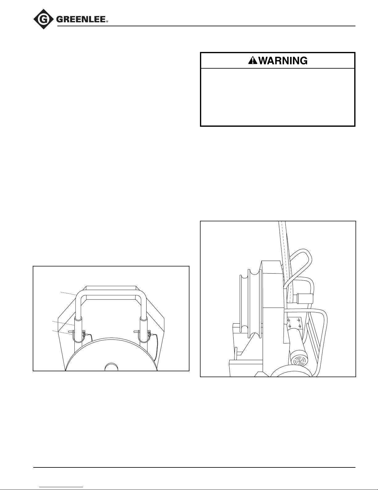
555®-22 Electric Bender
Handle Removal and Replacement
The handle of the 555®-22 is designed to be removable.
This feature is convenient when performing complex
bending, and makes it easy to replace a damaged
handle.
Removal
1. Place the bender in the upright position.
2. Release the spring clip on the safety snap pin (79).
3. Remove the pin from the handle (80) and the sleeve
of the frame (1).
4. Repeat Steps 1 through 3 for the other end of the
handle.
5. Lift the handle to remove.
Replacement
1. Insert the handle (80) into the sleeves of the frame (1).
2. Align the holes in the handle with the holes in the
sleeves.
3. Insert the safety snap pin (79). Ensure that the pin
goes through the handle and the sleeve on the
frame (1).
4. Engage the safety spring clip over the end of the pin.
Ensure that the loop on the clip is completely around
the pin.
5. Repeat Steps 2 through 4 for the other end of the
handle.
Transportation
Make sure that the handle is properly installed and
secured with the safety spring clips and snap pins
before lifting or moving the bender. An improperly
installed handle could allow the bender to fall,
injuring nearby personnel.
Failure to observe this warning could result in severe
injury or death.
The only proper way to lift this bender is by attaching a
nylon or polyester sling around the storage spindle. The
sling should extend between the handle and main frame
of the bender so that the handle acts as a guide for the
sling, as shown.
Make sure that all components used to lift this bender
are properly rated for the 159 kg (350 lb) weight. Use a
ramp to load and unload from a truck or other vehicle
that is not equipped with a lift gate.
Transporting Bender
79
Removing or Replacing Handle
80
1
Greenlee / A Textron Company 25 4455 Boeing Dr. • Rockford, IL 61109-2988 USA • 815-397-7070
Page 26
Maintenance
There is no need for periodic flushing and replacing of
lube in the bender gear box since it is sealed and locked
tight. However, if the box is opened for repair and the
lube is lost or contaminated by dirt, then the box and
parts should be flushed out and filled with 26 fluid
ounces of Mobil® 634 synthetic oil.
Flushing should be accomplished with kerosene, which
is a petroleum hydrocarbon that does not affect seals.
Note: Aromatic hydrocarbons such as benzine,
chlorinated solvents such as carbon-tetrachloride, and
ketones such as acetone should never be used for
flushing as they are solvents for rubber. They are also
harmful to the environment.
Disconnect this tool when not in use,
before servicing or adjusting, and
when changing shoes or conduit
rollers and supports.
Failure to observe this warning could
result in severe injury or death.
555®-22 Electric Bender
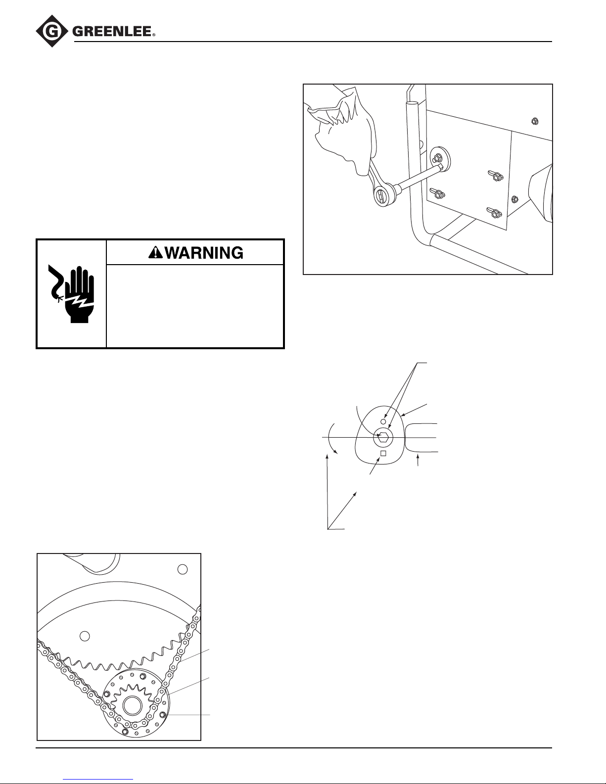
With the eight reductor mounting bolts (22, 24) loose,
rotate the eccentric cam with a 1/2" square drive to
tension the chain. Torque the eight reductor mounting
bolts to 47 Newton-meters (35 ft-lb).
Chain Adjustment
Both chains have to be adjusted if the final drive #60
chain is to be reset. Refer to the Exploded View and
Parts List.
1. Remove the front cover (38) and upper rear guard
(37).
2. Loosen the eight mounting bolts for the reductor
(19). Remove the eccentric cam and move the
reductor to create chain slack.
3. Remove the four retaining screws for eccentric
adjustment. Rotate to remove slack from the chain
and align with one of the two sets of holes in the
frame. Remount the eccentric with the four bolts.
4. Slide the reductor in slotted mounting holes to the
retension chain. Set tension with the eccentric cam.
#60 HT Final
Drive Chain
Two eccentric cam mounting
holes provided for varying
Reductor
Mounting Bolt
1/2" Square
Rotate eccentric cam counterclockwise.
Apply 20 Newton-meters (15 ft-lb) of torque to set
chain tension. Then torque reductor mounting bolts
to 47 Newton-meters (35 ft-lb).
adjustment positions
Eccentric Cam
Tab on
Reductor Bracket
Greenlee / A Textron Company 26 4455 Boeing Dr. • Rockford, IL 61109-2988 USA • 815-397-7070
Positioning Plate on
Eccentric Housing,
Counter Shaft
Four 1/4" Flange
Mounting Screws
Page 27
Maintenance (cont’d)
555®-22 Electric Bender
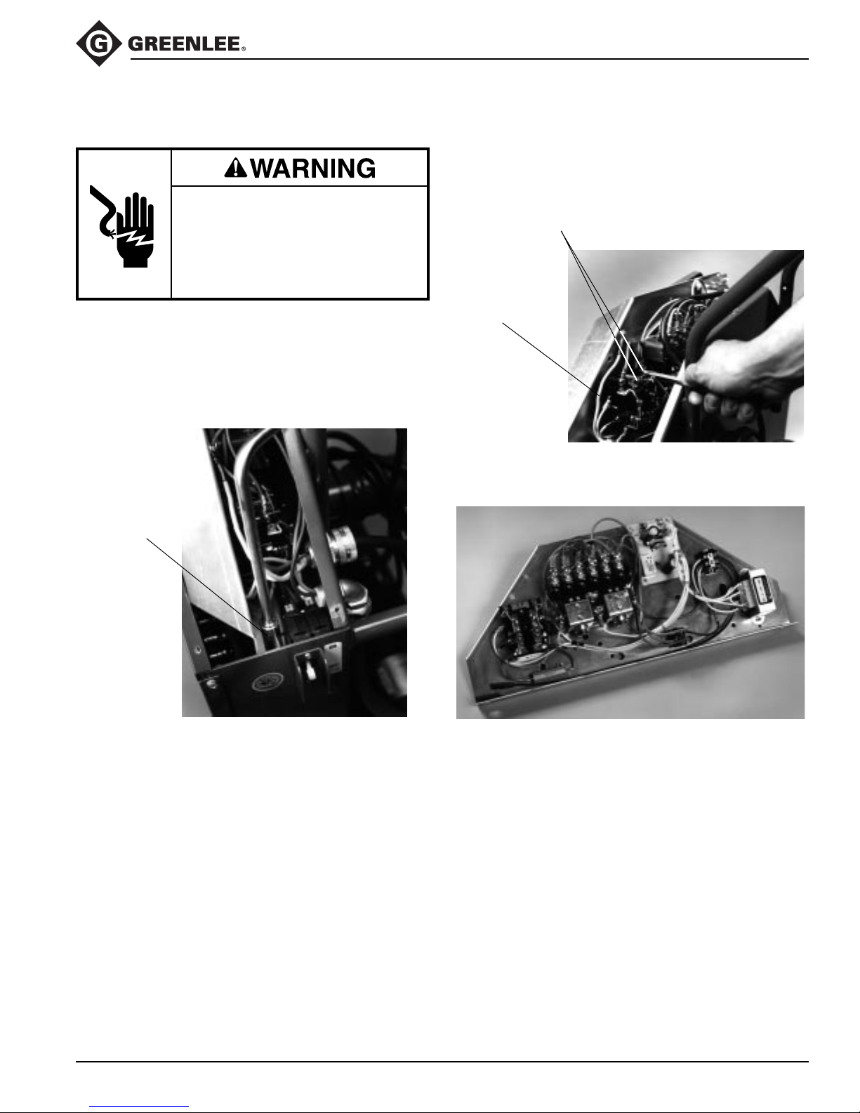
Electrical Control Unit Removal
Disconnect power supply before
servicing bender. Servicing to be done
only by trained service technician.
Failure to observe this warning could
result in severe injury or death.
1. Remove the cover retained by ten 5/16" hex screws.
2. Disconnect the pendant switch plug from the circuit
board and remove through the cord grip.
3. Remove two hex mounting screws, one on each
side.
3/8" Hex
Mounting
Screw
4. Remove the motor leads, power cord ground wire,
and neutral wire before the control unit can be totally
removed from the bender.
Motor Leads
Ground Wire
Electrical control removed from bender
Greenlee / A Textron Company 27 4455 Boeing Dr. • Rockford, IL 61109-2988 USA • 815-397-7070
Page 28

555®-22 Electric Bender
Troubleshooting
Problem Probable Cause Probable Remedy
Bender will not operate. No voltage. Check supply voltage circuit operation.
Check that switch is on.
Bends are overbent a few
degrees.
Bends are underbent a few
degrees.
Too much squeeze on 1-1/2" or 2"
EMT or IMC conduit.
Unusual conduit characteristics. Bend smaller angle to compensate.
Too little squeeze on 1-1/2" or 2"
EMT or IMC conduit.
Unusual conduit characteristics. Bend larger angle to compensate.
Back squeeze off per adjustment
instructions.
Increase squeeze per adjustment
instructions.
Greenlee / A Textron Company 28 4455 Boeing Dr. • Rockford, IL 61109-2988 USA • 815-397-7070
Page 29
Troubleshooting (cont’d)
555®-22 Electric Bender
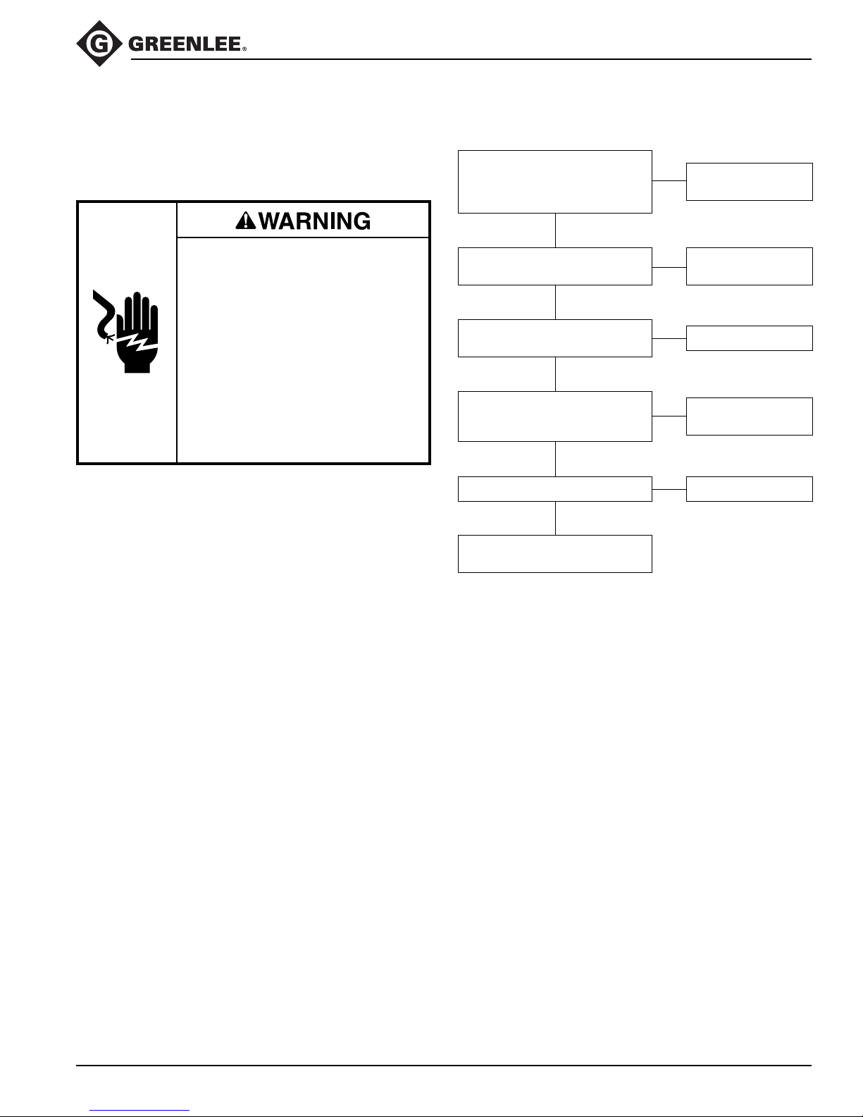
The following flow chart shows the suggested troubleshooting procedures when the bender trips the switch/
circuit breaker. It by no means encompasses all possible
problems or solutions.
Electric shock hazard:
• Contact with live circuits can result
in severe injury or death.
• Some troubleshooting steps
require power to the bender. This
type of troubleshooting step should
only be performed at authorized
Greenlee service centers by
personnel who are familiar with
safe troubleshooting procedures.
Failure to observe these warnings
could result in severe injury or death.
Trips 555®-22 Switch/Circuit Breaker
Are the proper roller supports and
shoe groove being used for the
type and size of conduit being
bent?
YES
Is the current on the 220 VAC line
exceeding 20 amps?
YES
Is the DC current to the motor
exceeding 17 amps?
NO
When BEND is pressed, is the
voltage sent to the motor
220 VDC (approx.)?
YES
Are connectors corroded?
NO
NO
NO
YES
NO
YES
Follow directions in
instruction manual.
Replace circuit
breaker.
Replace motor.
Replace bridge
rectifier (918 5997.2).
Clean the connectors.
Clean contacts or replace
contactor.
Greenlee / A Textron Company 29 4455 Boeing Dr. • Rockford, IL 61109-2988 USA • 815-397-7070
Page 30
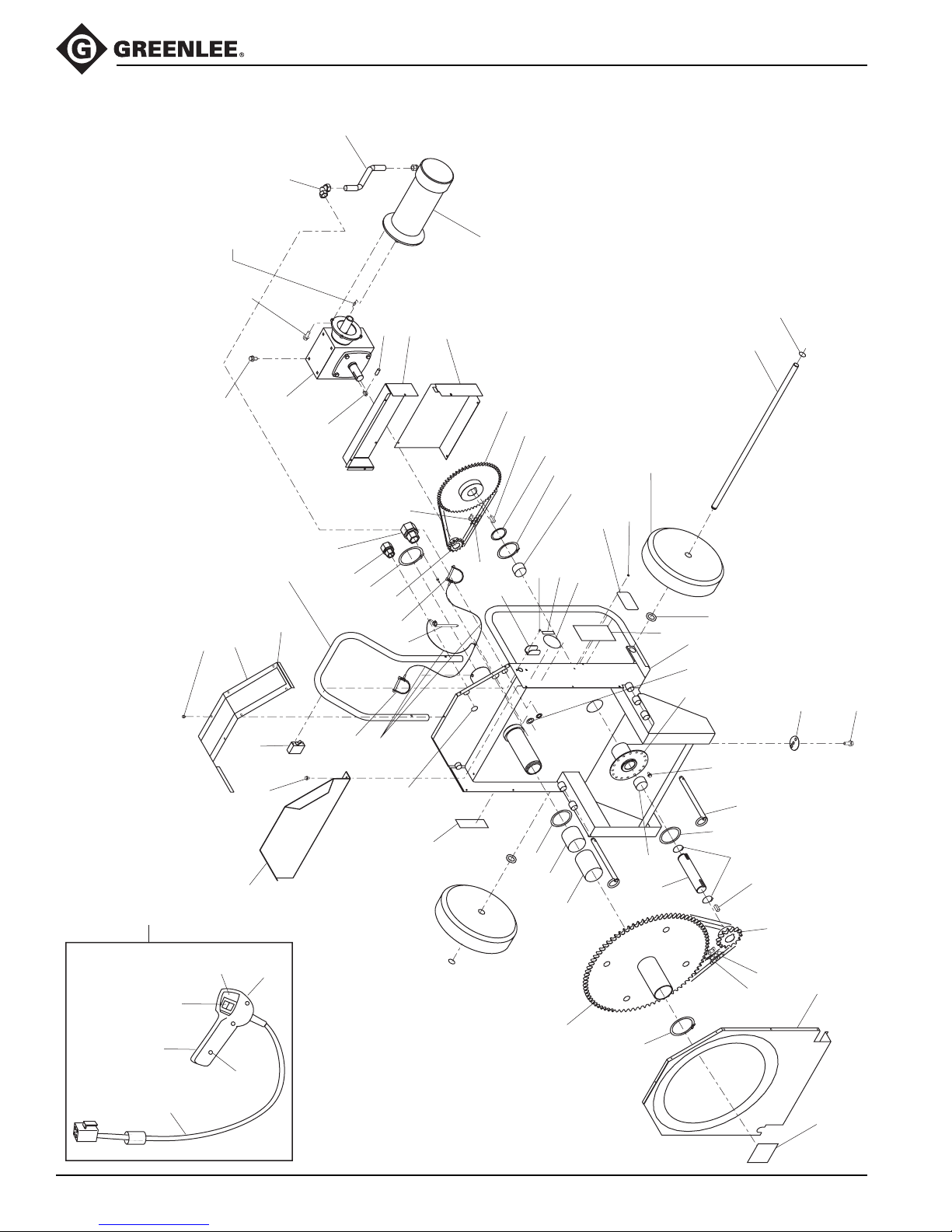
Exploded View — 555®-22 Electric Bender
26
27
Note: Key supplied
with item #19
(reductor).
24
37
59
36
555®-22 Electric Bender
25
34
32
62
39
22
47
77
41
54
19
80
71
18
28
30
79
50
52
17
79
20
53
31
57
21
42
12
14
11
9
7
43
58
40
46
2
4
5
44
35
7
10
72
70
1
29
8
23
54
49
11
78
14
13
24
62F
62A
62D
62E
Greenlee / A Textron Company 30 4455 Boeing Dr. • Rockford, IL 61109-2988 USA • 815-397-7070
62B
62C
16
15
3
6
38
48
Page 31

Parts List — 555®-22 Electric Bender
Key Part No. Description Qty
1 503 9742.7 Weldment, main frame ............................................................... 1
2 502 3452.8 Washer, fiber .............................................................................. 1
3 503 2896.4 Weldment, sprocket unit............................................................. 1
4 905 2409.8 Bearing, Fiberglide ø2.625 x 2.5 long ........................................ 1
5 905 2410.1 Bearing, Fiberglide ø2.625 x 3.75 long ...................................... 1
6 905 2414.4 Ring, retaining #5100-237 .......................................................... 1
7 905 2412.8 Bearing, Fiberglide ø1.625 x 1.00 long ...................................... 2
8 503 9763.0 Weldment, countershaft ............................................................. 1
9 905 4023.9 Ring, retaining #5100-250 .......................................................... 1
10 503 9764.8 Shaft, counter ............................................................................. 1
11 905 2413.6 Bearing, thrust Fiberglide ........................................................... 2
12 905 4548.6 Sprocket, #40 60T ...................................................................... 1
13 905 4253.3 Sprocket, #60 14T ...................................................................... 1
14 503 9765.6 Key, countershaft ....................................................................... 2
15 905 4546.0 Chain, #60 87P........................................................................... 1
16 905 4251.7 Masterlink, #60 ........................................................................... 1
17 905 4547.8 Sprocket, #40 13T ...................................................................... 1
18 500 8431.3 Key, reductor sprocket ............................................................... 1
19 905 2388.1 Reductor, worm gear .................................................................. 1
20 905 2787.9 Masterlink, #40 ........................................................................... 1
21 905 4551.6 Chain, #40 87P........................................................................... 1
22 905 4568.0 Bolt, 3/8–16 UNC x .75............................................................... 7
23 503 9758.3 Eccentric ..................................................................................... 1
24 905 4237.1 Bolt, 3/8–16 UNC x 1.00............................................................. 5
25 918 5828.3 Motor, 220V ................................................................................ 1
26 905 4549.4 Conduit, Sealtight ....................................................................... 1
27 918 5214.5 Elbow, Sealtight.......................................................................... 1
28 918 6683.9 Strain relief ................................................................................. 1
29 905 1170.0 Nut, 3/4 conduit lock ................................................................... 1
30 918 6767.3 Strain relief, pendant switch ....................................................... 1
31 918 6263.9 Nut, 1/2 conduit lock ................................................................... 1
32 503 9757.5 Axle............................................................................................. 1
34 905 1528.5 Ring, retaining #5160-75 ............................................................ 2
35 905 3390.9 Wheel ......................................................................................... 2
36 503 9768.0 Guard, rear lower ....................................................................... 1
37 503 9769.9 Guard, rear upper ....................................................................... 1
38 503 9760.5 Cover, front................................................................................. 1
39 905 1655.9 Screw, #10–16 x .50 hex head................................................. 31
40 905 0430.5 Screw, #6–32 x .375 Phillips ...................................................... 2
41 918 6785.1 Switch, Potter & Brumfield.......................................................... 1
42 502 9708.2 Guard, switch.............................................................................. 1
43 502 3839.6 Nameplate .................................................................................. 1
44 905 3001.2 Rivet, pop 1/8 x 1/8 drive ........................................................... 4
555®-22 Electric Bender
Greenlee / A Textron Company 31 4455 Boeing Dr. • Rockford, IL 61109-2988 USA • 815-397-7070
Page 32

Parts List — 555®-22 Electric Bender (cont’d)
Key Part No. Description Qty
46 503 0392.9 Decal, damp warning.................................................................. 1
47 503 9759.1 Cover, top ................................................................................... 1
48 503 5191.5 Decal, safety............................................................................... 1
49 905 3389.5 Pin, hitch ..................................................................................... 2
50 905 2501.9 Ring, retaining #5100-287 .......................................................... 1
52 905 4552.4 Lanyard....................................................................................... 3
53 905 4545.1 Pin, hitch ..................................................................................... 1
54 905 4335.1 Screw, 1/4 x .37 thread-forming ................................................. 6
57 503 3937.0 Decal, squeeze adjust ................................................................ 1
58 503 8974.2 Decal, circuit breaker.................................................................. 1
59 905 5323.3 Pin, Driv-Lok, 1/8 x 1/2 ............................................................... 1
62 500 6913.6 Switch, pendant .......................................................................... 1
62A 918 6449.6 Switch, center off........................................................................ 1
62B 503 1902.7 Handle, right half ........................................................................ 1
62C 905 3441.7 Screw, #6–20 x .625 pan head, self-tapping.............................. 3
62D 503 1901.9 Handle, left half .......................................................................... 1
62E 503 9837.7 Cord ............................................................................................ 1
62F 503 5487.6 Decal, face plate......................................................................... 1
555®-22 Electric Bender
65 905 4329.7 Screw, #8–32 x .37 ground ........................................................ 1
70 905 1740.7 Washer, flat ................................................................................ 2
71 500 2497.3 Decal, instruction ........................................................................ 1
72 905 3724.6 Washer, internal tooth lock......................................................... 1
77 500 0036.5 Electronic control assembly ....................................................... 1
78 905 1051.8 Ring, retaining #5100-150 .......................................................... 2
79 905 5268.7 Pin, safety snap .......................................................................... 2
80 503 9748.6 Handle, upper ............................................................................. 1
Greenlee / A Textron Company 32 4455 Boeing Dr. • Rockford, IL 61109-2988 USA • 815-397-7070
Page 33
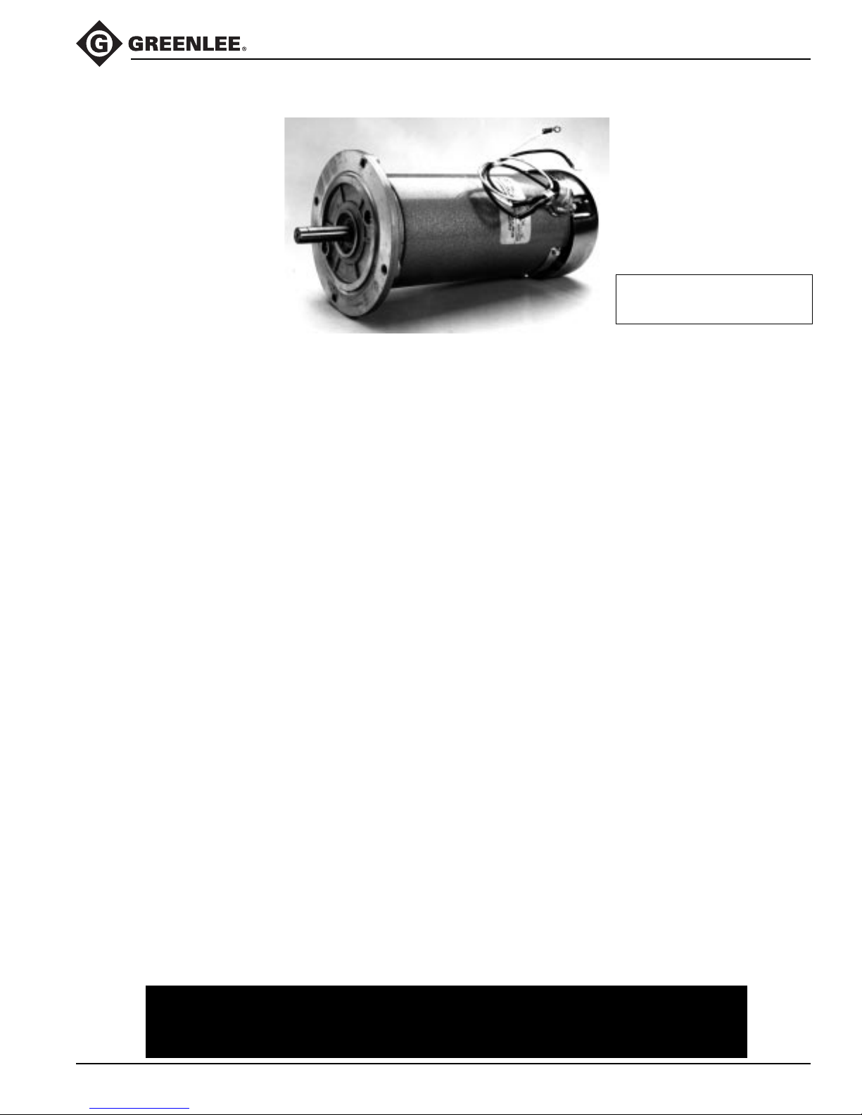
Motor Parts List – 220V
918 5828.3 Motor – 220 volt (standard) ....................... 1
918 6418.6 Bell, front end............................................. 1
918 6252.3 Bell, rear end ............................................. 1
918 6420.8 Brush.......................................................... 2
918 6421.6 Bearing kit.................................................. 2
918 6422.4 Thrust washer............................................ 1
918 6423.2 Terminal cover........................................... 1
918 6424.0 Retaining ring............................................. 1
918 6249.3 Armature, 220V.......................................... 1
918 6426.7 Tie bolt ....................................................... 2
918 6427.5 Shell & magnet assembly.......................... 1
918 6428.3 End bell nut................................................ 2
918 6429.1 Terminal cover screw ................................ 2
918 6430.5 Brush cover................................................ 2
918 6431.3 Cover screw............................................... 2
918 6432.1 Fan............................................................. 1
918 5876.3 90° Connector............................................ 1
555®-22 Electric Bender
When ordering parts, give
serial number of bender.
Pacific Scientific
Part No. Description Qty
Leeson Motors
Part No. Description Qty
918 5828.3 Motor – 230 volt D.C.................................. 1
918 6251.5 Bell, front end............................................. 1
918 6252.5 Bell, rear end ............................................. 1
918 6253.1 Brush/plate assembly ................................ 2
918 6250.7 Bearing 203 dbl. shielded.......................... 2
918 6258.2 Thrust washer - wave spring ..................... 2
918 6255.8 Terminal cover........................................... 1
918 6259.0 Terminal cover........................................... 1
918 6249.3 Armature, 230V.......................................... 1
905 3613.4 Tie bolt, #10-32 x 3-1/4 lg. front ................ 4
905 3614.2 Tie bolt, #10-32 x 1-3/4 lg. rear................. 4
918 6247.7 Frame - 48 ................................................. 1
905 0750.9 Lock washer-brush #10-32 inter. tooth ..... 4
905 2626.0 Cover screw-brush #10-32 x 1/2
round head machine .............................. 4
918 6256.6 Brush cover................................................ 2
918 6257.4 Brush cover insulation ............................... 2
For parts not shown contact your nearest Authorized Greenlee
Service Station or call 800-435-0786 for more information.
Greenlee / A Textron Company 33 4455 Boeing Dr. • Rockford, IL 61109-2988 USA • 815-397-7070
Page 34
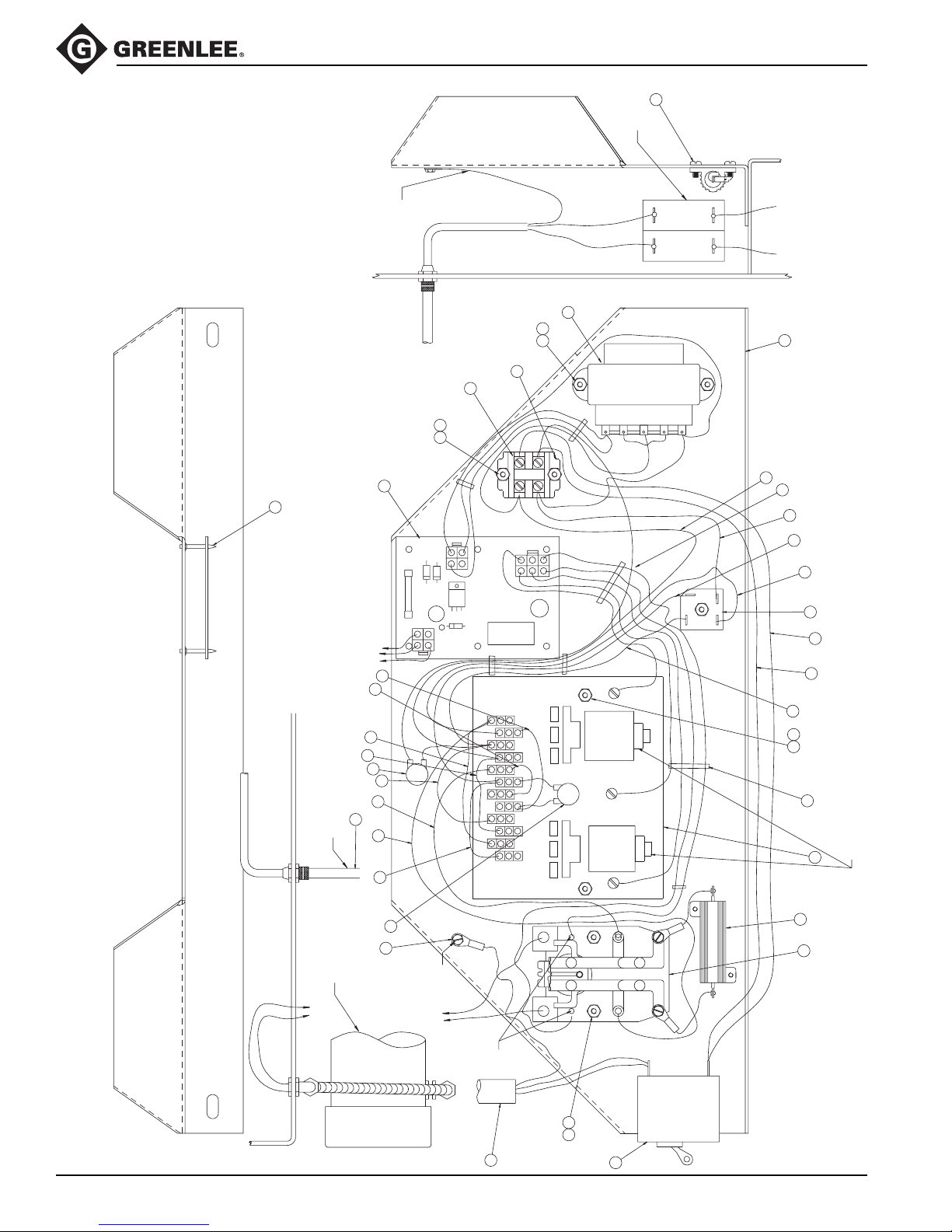
555®-22 Electric Bender
Layout — Electrical
Control System
73
BREAKER
31
WHITE
BLACK
WHITE
BLACK
See pages 33 and 36
for part numbers.
16
9
Complete replacement electrical
assembly available as 500 0036.5.
32
33
34
5
29
30
34
20
18
51
NOTE: Route wires to be clear of coil armatures.
2
(GREEN)
GROUND
20
18
8
7
POWER CORD
20
18
2
BLACK
BLUE
TERM
BOARD
1
RELAY
BLUE
UE
BL
3
17
PENDANT SWITCH
25
35
26
36
37
11
PENDANT SWITCH CORD
VAR
24
28
27
25
GREY
RED
BLUE
GREY
WHITE
BLACK
4
TRAN.
230V
BLACK
PURPLE
U
CON
VAR
B
CON
115V
WHITE
LINE
RED
LINE
BLUE
BLACK
RED
BLACK
LOAD
LOAD
PURPLE
AC
+HV
AC
-HV
REC
WHITE
RED
Greenlee / A Textron Company 34 4455 Boeing Dr. • Rockford, IL 61109-2988 USA • 815-397-7070
MOTOR 240V
15
21
GROUND
BLACK
TO MOTOR
WHITE
BLACK
WHITE
LINE
14
PENDANT
COIL
GREEN
1920
10
BREAKER
2 POLE
R1
LOAD
6
1
Page 35

Parts List — Electrical Control System
Key Part No. Description Qty
1 918 6781.9 CR1............................................................................................. 1
2 918 6783.5 Bend and unload contactor ........................................................ 1
3 918 6782.7 Circuit board with time delay switch ........................................... 1
4 918 6784.3 Transformer assembly................................................................ 1
5 918 5888.7 Rectifier ...................................................................................... 1
6 918 6772.0 Resistor, Dale ............................................................................. 1
7 918 5872.0 Terminal block, Buchannan........................................................ 2
8 918 5996.4 End piece, Buchannan ............................................................... 1
9 503 9972.1 Control cable .............................................................................. 1
10 503 9973.0 Power cord ................................................................................. 1
11 503 9839.3 Pendant unit ............................................................................... 1
14 918 6785.1 Circuit breaker, Potter Brumfield ............................................... 1
15 500 0034.9 Varistor unit ................................................................................ 2
16 503 9969.1 Bracket, mounting, electrical control .......................................... 1
17 918 6644.8 Support, LCBS, Richco .............................................................. 6
18 905 4330.0 Screw, #6-32 x .50 Phillips head ................................................ 7
19 905 4331.9 Screw, #6-32 x .75 Phillips head ................................................ 2
20 905 0632.4 Nut, hex #6-32 ............................................................................ 9
21 905 4329.7 Screw, ground #8-32 x .37 ......................................................... 1
24 503 9994.2 Jumper, red 3.50" ....................................................................... 1
25 503 9995.0 Jumper, blue terminal to terminal 3.50" ..................................... 2
26 503 9996.9 Jumper, blue terminal to terminal 5.50" ..................................... 1
27 500 0031.4 Jumper, grey to CR1 coil 18.00" ................................................ 1
28 500 0020.9 Jumper, grey to CR1 coil 12.00" ................................................ 1
29 500 0021.7 Jumper, black breaker to terminal block 20.50" ......................... 1
30 500 0025.0 Jumper, white breaker to terminal block 20.50" ......................... 1
31 500 0019.5 Jumper, red terminal block to BCON-UCON 14.00" .................. 1
32 500 0028.4 Jumper, purple terminal block to Rec. 20.50" ............................ 1
33 503 9975.6 Wire unit, red rec. to B&U contactor 15.00" ............................... 1
34 503 9974.8 Wire unit, black rec. to B&U contactor 14.00" ............................ 2
35 503 9993.4 Jumper, blue terminal to terminal 1.50" ..................................... 1
36 503 9992.6 Jumper, black terminal to terminal 3.50" .................................... 1
37 500 0035.7 Varistor unit ................................................................................ 1
51 905 4279.7 Tie, wrap ..................................................................................... 7
52 905 3724.6 Washer, internal lock .................................................................. 1
555®-22 Electric Bender
Greenlee / A Textron Company 35 4455 Boeing Dr. • Rockford, IL 61109-2988 USA • 815-397-7070
Page 36
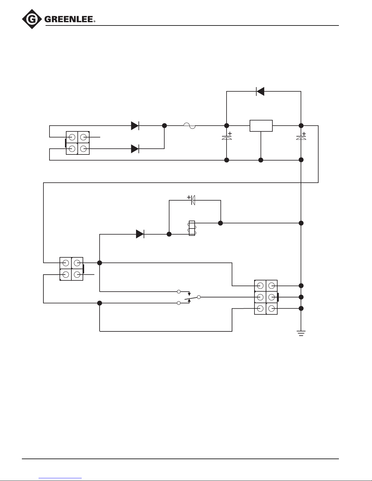
Bender Control Schematic Diagram
555®-22 Electric Bender
1N4007
KA
D1
TRANSFORMER
3
4
PENDANT
1
2
UNLOAD
J2
J1
3
BEND
4
1N5400
A K
1
D2
F1
3A / 250V
1N5400
2
AK
D3
C2 C1
4700µF
NTE1936
VI
G
U1
VO
12V
100µF
1200µF
C3
D4
AK
1N4007
K1:A
L1
TIME DELAY
L2
RELAYS
BEND
TIME DELAY
C2
C3
K1:B
C1
BRAKE
UNLOAD
3
2
1
6
5
4
J3
Greenlee / A Textron Company 36 4455 Boeing Dr. • Rockford, IL 61109-2988 USA • 815-397-7070
GND
Page 37
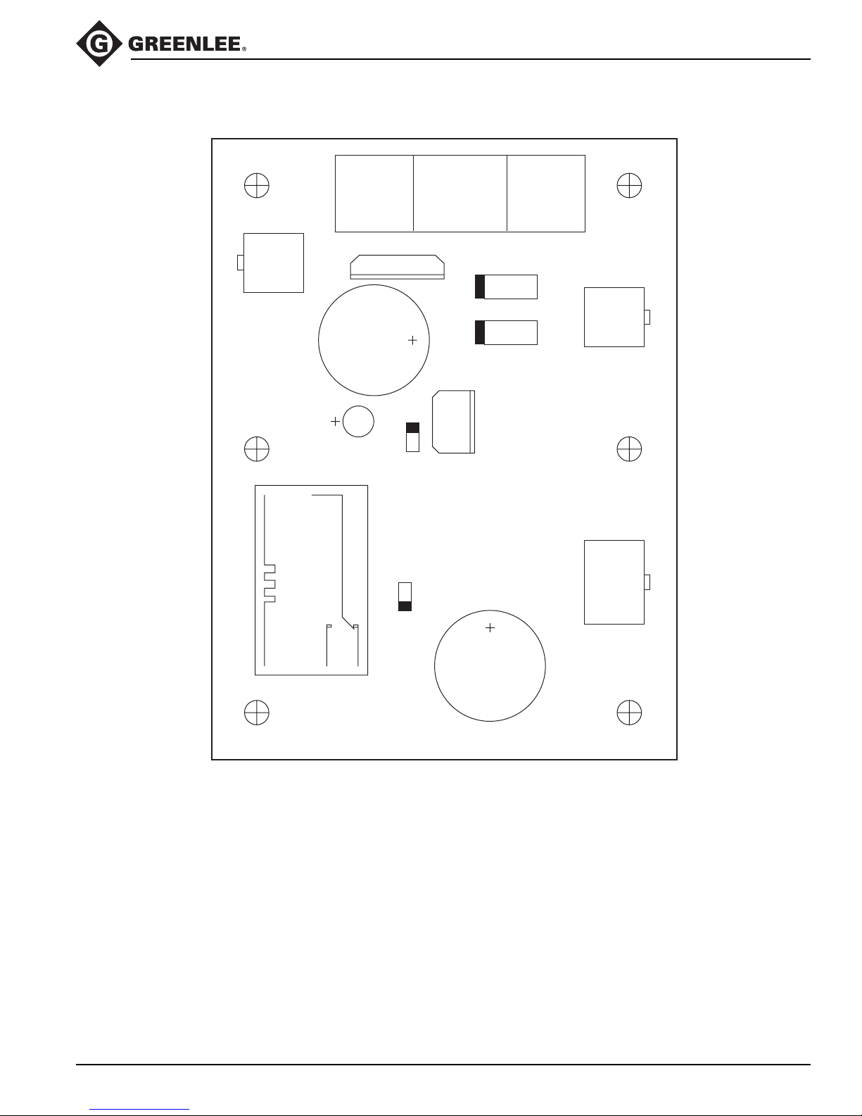
555®-22 Electric Bender
Diagram and Parts List — Bender Control Printed Circuit Board
PENDANT
3
4
1
2
K1
U1
C1
3 AMP / 250 VOLT
FUSE
C2
D1
D4
U1
C3
D3
D2
F1
2
1
3
22
1
TRANSFORMER
4
3
6
RELAYS
5
4
Key Part No. Manufacturer Description Qty
U1 NTE1936 NTE 12V Regulator................................1
F1 312.003 Littelfuse 3A Fuse .........................................1
C1 UVX1E101MEA Nichicon 100µF/25V Capacitor.....................1
C2 ECE-A1EU472 Panasonic 4700µF Capacitor ..........................1
C3 EEU-FC1E122S Panasonic 1200µF Capacitor ..........................1
D1, 4 1N4007 Any Diode .............................................2
D2, 3 1N5400 Any Diode .............................................2
K1 CR50-E2-X1-12 Computer Components Inc. Relay..............................................1
J1, 2 39-28-1043 Molex 4 Pin Minifit Jr. Connector .............2
J3 39-28-1063 Molex 6 Pin Minifit Jr. Connector .............1
Greenlee / A Textron Company 37 4455 Boeing Dr. • Rockford, IL 61109-2988 USA • 815-397-7070
9186782.7
GREENLEE TEXTRON INC.
Page 38
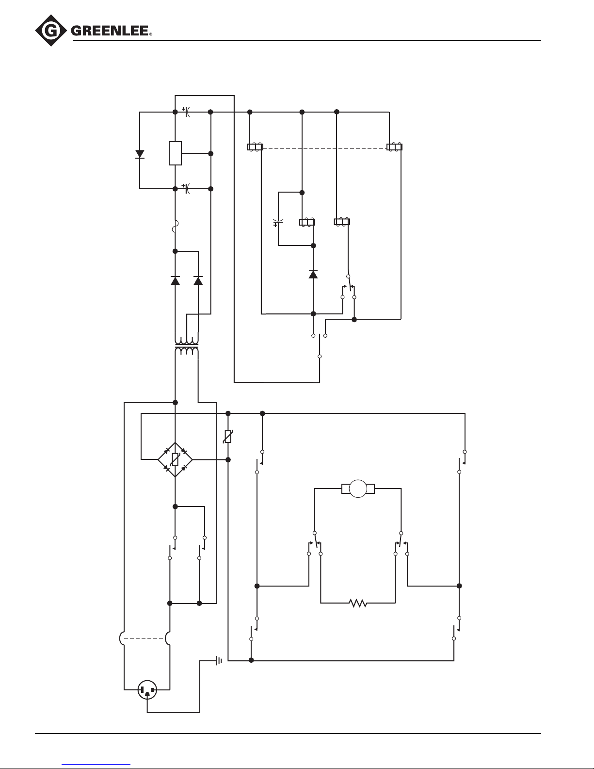
Control and Power Unit Schematic Diagram
100µF
L2
K1:A
L1
BEND CONTACTOR
L2
1N4007
K A
D1
12V
VO
2
G
VI
U1
NTE1936
13
C2 C1
4700µF
555®-22 Electric Bender
L2
K4:A
L1
L2
UNLOAD CONTACTOR
F1
1N5400
A K
D2
P1 S1T1
R2
3A / 250V
S2
1N5400
AK
D3
220:20
P2 S3
R3
BR1
K4:C
K1:A
1200µF
C3
K3:A
L1
D4
AK
C3
TIME DELAY
1N4007
C2
L1
C1
TIME DELAY
C2
BRAKE RELAY
K1:B
C3
S1
PENDANT
C1
C4
M1
220 VDC
C4
K1:C
C3
C2
K1:B
CB1A
K4:B
C1
C1
CB1B
J1
AC PLUG
Greenlee / A Textron Company 38 4455 Boeing Dr. • Rockford, IL 61109-2988 USA • 815-397-7070
C2
C1
K3:B
C2
C3
2 OHM
50 WATT
C6 C3
R1
K1:D
GND
C5
K3:C
C6
C4
C5
C6
K4:D
C5
Page 39
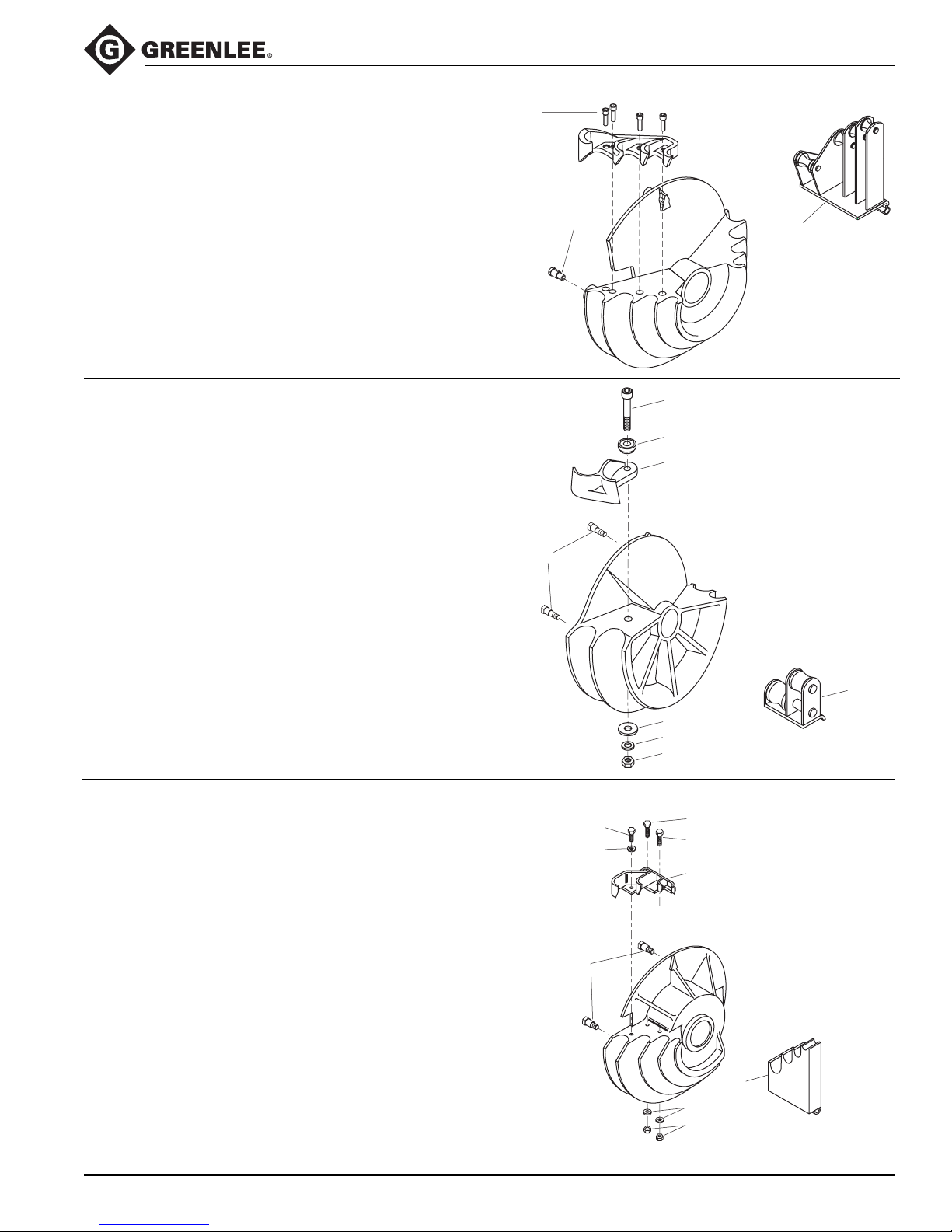
555C Electric Bender Classic
Bending Shoes and Roller Supports
Bending Shoe and Roller Support
1/2" to 1-1/4" IMC and Rigid Conduit
Key Part No. Description Qty
1 500 0936.2 Roller support, 1/2" to 1-1/4"
IMC and Rigid...................................... 1
500 0571.5 Bending shoe assembly
(includes items 2–4) ............................ 1
2 500 0569.3 Hook .................................................... 1
3 905 1088.7 3/8–16 UNC x 1-1/4"
Socket head cap screw ....................... 4
4 502 3422.6 Stud, drive ........................................... 3
Shoe not available separately.
Bending Shoe and Roller Support
1-1/2" to 2" Rigid Conduit
Key Part No. Description Qty
1 501 7984.5 Roller support, 1-1/2" to 2"
rigid conduit ......................................... 1
501 7937.3 Bending shoe assembly,
1-1/2" to 2" Rigid conduit
(includes items 2–8) ............................ 1
2 501 7969.1 Pipe hook............................................. 1
3 501 7974.8 Pivot..................................................... 1
4 905 2675.9 5/8 flat washer ..................................... 1
5 905 1569.2 5/8–11 UNC hex nut ............................ 1
6 905 0905.6 5/8 split lock washer ............................ 1
7 905 2426.8 5/8–11 UNC x 4" Socket head
cap screw ............................................ 1
8 502 3422.6 Stud, drive ........................................... 4
Shoe not available separately.
3
2
4
7
3
2
8
4
6
5
1
1
Bending Shoe and Pipe Rest
1/2" to 1-1/4" EMT Conduit
Key Part No. Description Qty
1 501 7986.1 Pipe rest assembly for
1/2" to 1-1/4" EMT conduit .................. 1
501 7944.6 Bending shoe assembly for
1/2" to 2-1/4" EMT conduit
(includes items 2–8) ............................ 1
2 905 0597.2 3/8–16 UNC x Socket head
cap screw ............................................ 1
3 905 0506.9 3/8 Lock washer (split) ........................ 3
4 502 4555.4 Pipe hook............................................. 1
5 502 3422.6 Stud, drive ........................................... 4
6 905 0639.1 3/8–16 UNC hex nut, cad. plated ........ 2
7 905 0532.8 3/8–16 UNC x 1-1/4 SAE grade 5
socket head cap screw........................ 1
8 905 1088.7 3/8–16 UNC x 1-1/4
socket head screw............................... 1
Shoe not available separately.
Greenlee / A Textron Company 39 4455 Boeing Dr. • Rockford, IL 61109-2988 USA • 815-397-7070
2
3
5
7
8
4
1
3
6
Page 40
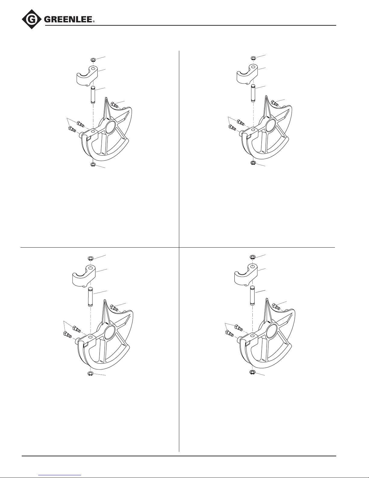
Bending Shoes and Roller Supports (cont’d)
555C Electric Bender Classic
4
1
2
3
3
Bending Shoe
4
1-1/2" EMT Conduit
Key Part No. Description Qty
502 3499.4 Shoe unit, 1-1/2" EMT
(includes items 1–4) ......................1
1 501 8820.8 Hook, 1-1/2" EMT ..........................1
2 501 8841.0 Pin, 1-1/2" EMT hook .................... 1
3 502 3422.6 Stud, drive ..................................... 3
4 905 1529.3 Ring, Tru-Arc #5160-87
retaining.........................................2
4
1
2
3
3
Bending Shoe
4
1-1/2" IMC Conduit
Key Part No. Description Qty
502 5363.1 Shoe unit, 1-1/2" IMC
(includes items 1–4) ......................1
1 501 8811.9 Hook, 1-1/2" IMC ...........................1
2 501 8837.2 Pin, 1-1/2" IMC .............................. 1
3 502 3422.6 Stud, drive .....................................3
4 905 1528.5 Ring, Tru-Arc retaining .................. 2
4
1
2
3
3
Bending Shoe
4
2" EMT Conduit
Key Part No. Description Qty
502 3505.2 Shoe unit, 2" EMT conduit
(includes items 1–4) ......................1
1 501 8818.6 Hook, 2" EMT ................................1
2 501 8842.9 Pin, 2" EMT hook........................... 1
3 502 3422.6 Stud, drive .....................................3
4 905 1529.3 Ring, Tru-Arc #5160-87
3
Bending Shoe
2" IMC Conduit
Key Part No. Description Qty
502 5268.2 Shoe unit, 2" IMC
(includes items 1–4) ......................1
1 500 0195.7 Hook, 2" IMC .................................1
2 501 8842.9 Pin, 2" IMC .................................... 1
3 502 3422.6 Stud, drive .....................................3
4 905 1529.3 Ring, Tru-Arc retaining .................. 2
4
1
2
3
4
retaining.........................................2
Greenlee / A Textron Company 40 4455 Boeing Dr. • Rockford, IL 61109-2988 USA • 815-397-7070
Page 41
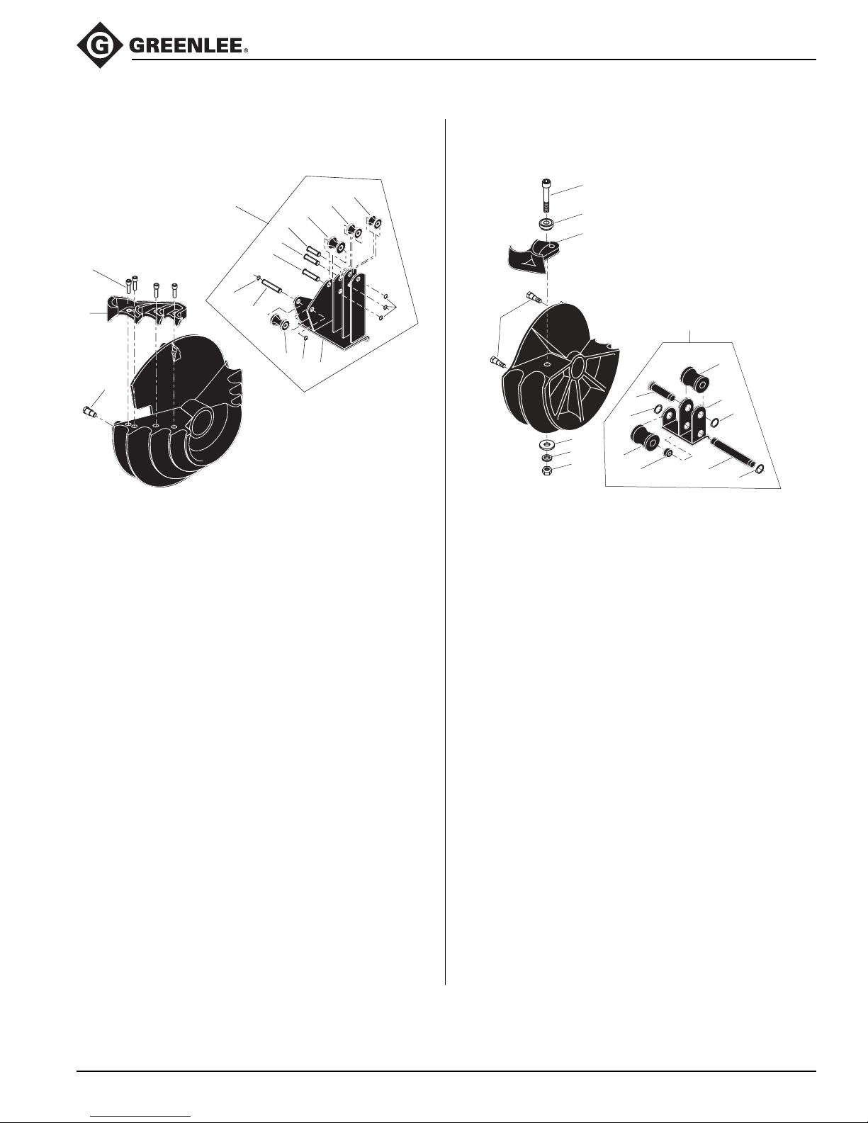
Bending Shoes and Roller Supports (cont’d)
555C Electric Bender Classic
11
1
7
8
9
3
6
2
4
10
14
13
12
6
6
5
Bending Shoe and Roller Support
1/2" to 1-1/4" 40 Mil PVC-Coated Rigid Conduit
Key Part No. Description Qty
1 500 0946.0 Roller support, 1/2" to 1-1/4"
PVC-coated Rigid
(includes items 5–14) ....................1
500 0573.1 Bending shoe assembly,
1/2" to 1-1/4" PVC-coated Rigid
(includes items 2–4) ......................1
2 500 0570.7 Hook ..............................................1
3 905 1088.7 3/8–16 UNC x 1-1/4"
Socket head cap screw .................4
4 502 3422.6 Stud, drive .....................................3
5 500 0945.1 Support weldment, roller ...............1
6 905 1353.3 Retaining ring ................................5
7 500 0923.0 1/2" roller axle................................ 1
8 500 0924.9 3/4" roller axle................................ 1
9 500 0925.7 1" roller axle...................................1
10 500 0926.5 1-1/4" roller axle ............................ 1
11 500 0927.3 1/2" roller .......................................1
12 500 0928.1 3/4" roller .......................................1
13 500 0929.0 1" roller ..........................................1
14 500 0930.3 1-1/4" roller ....................................1
7
3
2
8
9
11
4
6
13
5
15
1
12
14
11
10
11
Bending Shoe and Roller Support
1-1/2" to 2" 40 Mil PVC-Coated Rigid Conduit
Key Part No. Description Qty
1 503 7282.3 Roller support, 1-1/2" to 2"
PVC-coated Rigid.......................... 1
(includes items 9–15) ......................
503 7281.5 Bending shoe assembly,
1-1/2" to 2" PVC
(includes items 2–8) ......................1
2 500 2499.0 Hook ..............................................1
3 501 7974.8 Pivot...............................................1
4 905 2675.9 5/8" Flat washer............................. 1
5 905 1569.2 5/8–11 UNC Hex nut ..................... 1
6 905 0905.6 5/8" Lock washer ...........................1
7 905 2426.8 5/8–11 UNC x 4"
Socket head cap screw .................1
8 502 3422.6 Stud, drive .....................................4
9 503 7662.4 1-1/2" Shaft.................................... 1
10 503 7661.6 2" Shaft ..........................................1
11 905 1528.5 Retaining ring ................................3
12 503 7284.0 1-1/2" Roller...................................1
13 503 7283.1 2" Roller .........................................1
14 503 7664.0 Support weldment ......................... 1
15 503 2025.4 Spacer ...........................................1
Greenlee / A Textron Company 41 4455 Boeing Dr. • Rockford, IL 61109-2988 USA • 815-397-7070
Page 42
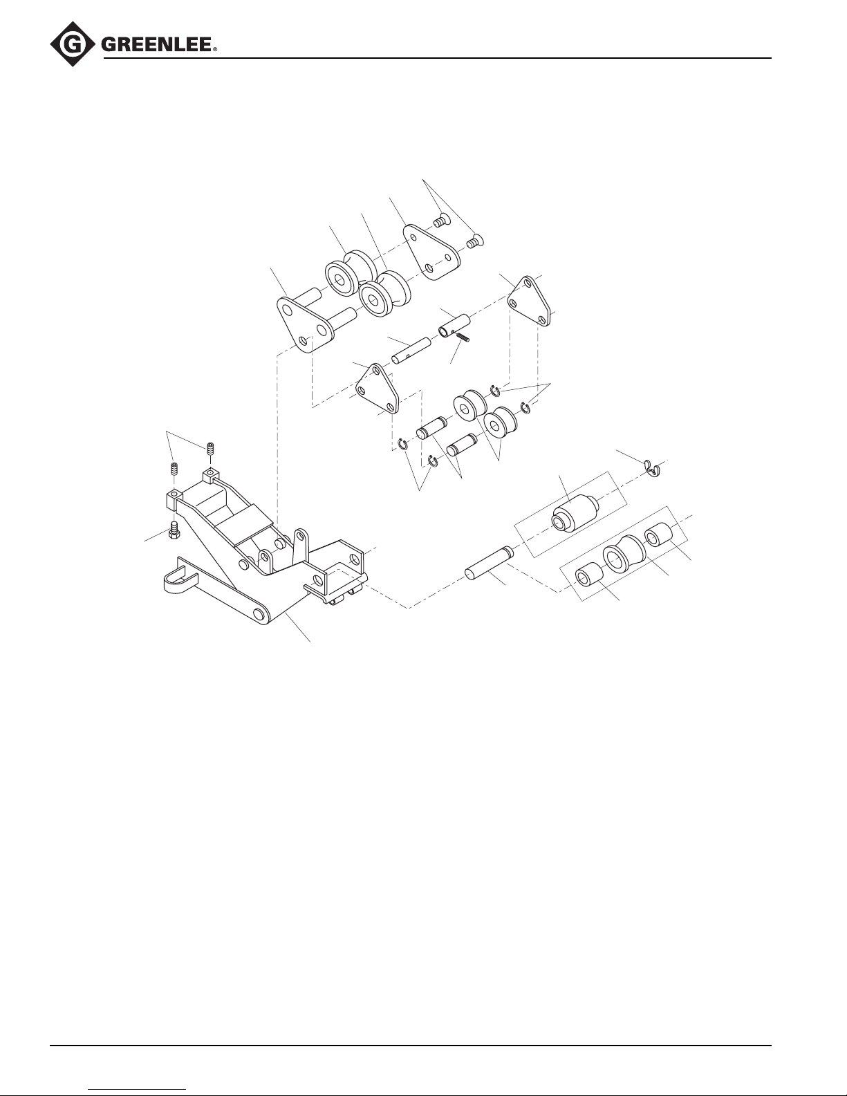
Bending Shoes and Roller Supports (cont’d)
21*
18
20
19
555C Electric Bender Classic
16
15
17
10
11
8
10
14
5
7
12
6
4
EMT
12
1A
13
2
1B
IMC
2
Greenlee / A Textron Company 42 4455 Boeing Dr. • Rockford, IL 61109-2988 USA • 815-397-7070
Page 43

Bending Shoes and Roller Supports (cont’d)
555C Electric Bender Classic
EMT Roller Support Unit
Key Part No. Description Qty
502 3541.9 Support unit,
1-1/2" and 2" EMT roller
(includes all of the following) ......... 1
1A 502 7983.1 Roller unit, cushioned....................1
4 502 3539.7 Frame unit ..................................... 1
5 502 3510.9 Roller, 1-1/2" EMT .........................2
6 502 3511.7 Pin, roller support .......................... 1
7 502 3932.5 Pin, 1-1/2" EMT roller .................... 2
8 502 3517.6 Pin, roller pivot...............................1
10 502 3524.9 Plate, 1-1/2" EMT pivot ................. 2
11 502 3793.4 Spacer ...........................................1
12 905 1528.5 Ring, retaining ...............................4
13 905 2464.0 Ring, Tru-Arc #X5133-98
external series “E” retaining .......... 1
14 905 1491.2 Rollpin, #59, -040-187-1250..........1
15 905 2848.4 Screw, 1/2–13 UNC x 3/4
cup pt. skt. set ............................... 2
16 905 0542.5 Screw, 1/2–13 UNC x 1
hex head cap ................................. 2
17 503 4964.3 Support weldment, 2" roller ...........1
18 503 4965.1 Plate, 2" inner roller support .......... 1
19 502 3519.2 Roller, 2" EMT front .......................1
20 502 3792.6 Roller, 2" EMT back....................... 1
21* 905 3394.1 Screw, 7/16–14 UNC x 1
flat head.........................................2
IMC Roller Support Unit
Key Part No. Description Qty
502 5273.9 Support unit,
1-1/2" and 2" IMC roller
(includes items 1 and 2) ................1
1B 502 8334.0 Roller ............................................. 1
2 502 8335.9 Spacer ...........................................2
4 502 6325.0 Frame unit ..................................... 1
5 502 5274.7 Roller, 1-1/2" IMC ..........................2
6 502 3511.7 Pin, roller support .......................... 1
7 502 3932.5 Pin, 1-1/2" IMC roller .....................2
8 502 3517.6 Pin, roller pivot...............................1
10 502 3524.9 Plate, 1-1/2" IMC pivot .................. 2
11 502 3793.4 Spacer ...........................................1
12 905 1528.5 Ring, retaining ...............................4
13 905 2464.0 Ring, Tru-Arc #X5133-98
external series “E” retaining .......... 1
14 905 1491.2 Rollpin, #59, -040-187-1250..........1
15 905 2848.4 Screw, 1/2–13 UNC x 3/4
cup pt. skt. set ............................... 2
16 905 0542.5 Screw, 1/2–13 UNC x 1
hex head cap ................................. 2
17 503 4964.3 Support weldment, 2" roller ...........1
18 503 4965.1 Plate, 2" inner roller support .......... 1
19 502 5279.8 Roller, 2" IMC ................................2
21* 905 3394.1 Screw, 7/16–14 UNC x 1
flat head.........................................2
*Key No. 21 must be torqued to 54 to 61 Newton-meters (40 to 45 ft-lb).
Greenlee / A Textron Company 43 4455 Boeing Dr. • Rockford, IL 61109-2988 USA • 815-397-7070
Page 44

USA 800-435-0786 Fax: 800-451-2632
815-397-7070 Fax: 815-397-1865
Canada 800-435-0786 Fax: 800-524-2853
International +1-815-397-7070 Fax: +1-815-397-9247
4455 Boeing Drive • Rockford, IL 61109-2988 • USA • 815-397-7070
An ISO 9001 Company
www.greenlee.com
•
Greenlee Textron Inc. is a subsidiary of Textron Inc.
Printed in USA
 Loading...