

Page 1
INSTRUCTION MANUAL
999 2653.9 © 1998 Greenlee Textron IM 1329 1/98
Read and understand this material
before operating or servicing this test
instrument. Failure to understand how
to safely operate the test instrument
could result in an accident causing
serious injury or death.
The symbol above is used to call your attention
to instructions concerning your personal
safety. Watch for this symbol. It points out
important safety precautions. It means
“ATTENTION! Become alert! Your personal
safety is involved!” Read the message that
follows and be alert to the possibility of
personal injury or death.
SAFETY
ALERT
SYMBOL
Immediate hazards which, if not avoided,
WILL result in severe personal injury or death.
Hazards or unsafe practices which, if not
avoided, COULD result in severe personal
injury or death.
Hazards or unsafe practices which, if not
avoided, COULD result in minor personal
injury or property damage.
Electric shock hazard.
Do not use on live circuits.
Contact with live circuits can
result in severe injury or death.
A person who has not read
and does not understand all
operating instructions is not
qualified to operate this tool.
Failure to read and understand
safety instructions could
result in injury or death.
Greenlee Textron / Subsidiary of Textron Inc.
4455 Boeing Drive, Rockford, IL 61109-2988 USA
Customer Service (International): 815/397-7070
Fax: 815/397-1391
Customer Service (North America): 800/435-0786
Fax: 800/451-2632, 815/397-1865
Canada Fax: 800/524-2853
Do not use the test instrument
if it is wet or damaged. Electric
shock can result.
SA VE THESE
INSTRUCTIONS
Additional copies of this manual are
available upon request at no charge.
Do not attempt to repair this test instrument.
It contains no user-serviceable parts. Failure
to observe this precaution can result in
damage the instrument.
Replace weak or discharged batteries as soon
as either of these conditions is detected.
Continuity and Tracing
1. Select the wire pair to be traced.
2. Plug the modular plug into the receptacle, or
strip the wires and connect the 45081 to the
bare wires with the alligator clips.
3. Set the switch to CONTINUITY.
• If the LED glows, the wire pair has a short
circuit and cannot be traced. Repair or
replace the wire.
• If the LED does not glow, the wire pair
does not have a short circuit and can be
traced. Proceed to Step 4.
4. Set the switch to TONE. Hold the tracer near
the 45081 to check for the presence of tone.
5. Trace the wire.
Lifetime Limited Warranty
Greenlee warrants to the original purchaser of
these goods for use that these products will be
free from defects in workmanship and material
for their useful life, excepting normal wear and
abuse. This warranty is subject to the same terms
and conditions contained in Greenlee’s standard
one year limited warranty.
For all Test Instrument repairs, ship units Freight
Prepaid to: Greenlee Textron at 4411 Boeing Drive,
Rockford, IL 61109-2932 USA.
Mark all packages: Attention TEST INSTRUMENT
REPAIR. For items not covered under warranty
(such as dropped, abused, etc.), repair cost quote
available upon request.
Note: Prior to returning any test instrument,
please check replaceable batteries or
make sure the battery
is at full charge.
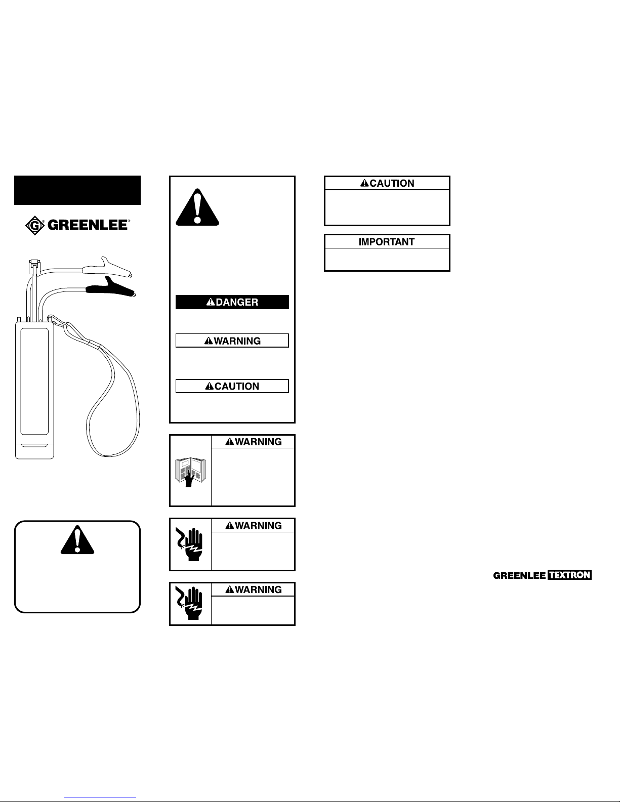
45081
TONE GENERA TOR
Description
The 45081 Tone Generator is intended to trace
wire pairs. It will produce a distinctive warbling
tone that a tracer can detect on each wire point.
For best results, use the 45081 Tone Generator
with the 45082 Pair Tracing Probe.
Specifications
Battery Quantity and Type ...................... one 9-volt
Output Level..............................-3 dBm (± 3 dBm)
Frequency .............1004 Hz ± 100 Hz Sweep Tone
Sweep Rate ....................................... 6 Hz nominal
Polarity/Voltage Test.................. to 1.5 kΩ at 50 V
Resistance Test..........................................to 1 kΩ
Polarity Testing
1. Set the switch to OFF/POL.
2. Strip the wires. Use the alligator clips to
connect the 45081 Tone Generator to the
wires. The LED will glow when the red
alligator clip is connected to the positive wire
and the black alligator clip is connected to the
negative wire.
• The LED glows brightly to indicate an
inactive line (on-hook condition).
• The LED glows dimly to indicate an active
line (off-hook condition) or faulty line.
Note: Do not set the switch to TONE –
this would send a loud warbling tone
to the customer.
 Loading...