

Page 1
INSTRUCTION MANUAL
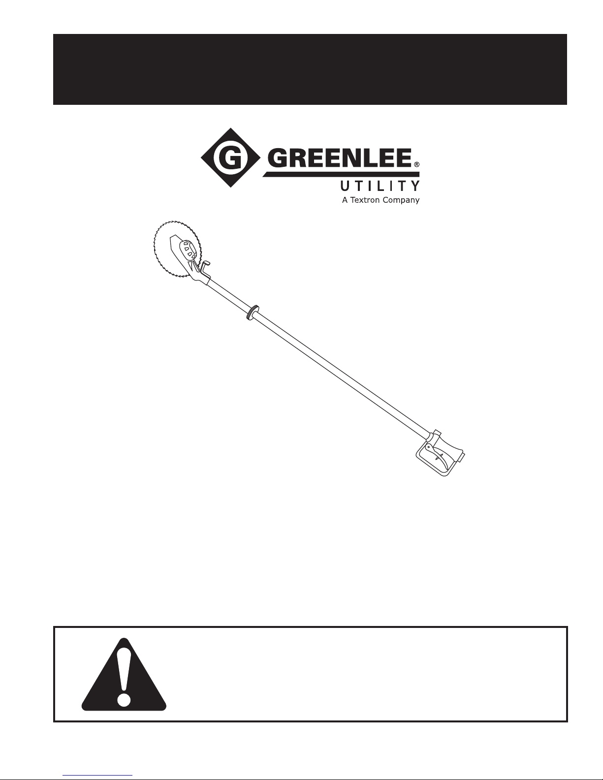
Overhead Circular Saw
Read and understand all of the instructions and
safety information in this manual before operating
or servicing this tool.
99913097 REV 11 © 2010 Greenlee Textron Inc. 10/10
43180
Register this product at www.greenlee.com
Page 2
43180 Overhead Circular Saw
Table of Contents
Description .................................................................... 2
Safety ............................................................................ 2
Purpose of this Manual ................................................. 2
Other Publications ......................................................... 2
Important Safety Information .....................................3–5
Identication .................................................................. 6
Specications .............................................................7–8
Hoses and Fittings ........................................................ 9
Hose Connections ......................................................... 9
Blade Removal/Installation .......................................... 10
Operation ..................................................................... 11
Maintenance ................................................................ 12
Troubleshooting ......................................................13–15
Disassembly ................................................................ 16
Inspection .................................................................... 17
Assembly ................................................................18–19
Illustrations and Parts Lists ....................................20–27
43180 Circular Saw .............................................20–21
Motor Assembly ..................................................22–23
Handle Assembly, Model Code FRN ..................24–25
Description
The Greenlee Utility 43180 Circular Saw is intended for
general tree trimming from the ground or from an aerial
device. A rugged, direct-drive motor provides enough
power for the 9" diameter blade to cut branches up
to 89 mm (3-1/2") in a single pass. The angled head
allows ush cuts while directing saw chips away from
the operator. The long-reach pole allows cutting in areas
that shorter tools cannot reach.
Flying debris hazard:
Do not use this saw for cutting or clearing at ground
level. If the blade contacts the ground or other solid
object, the operator can lose control of the saw and
the blade can shatter. Operator can be injured by
ying debris.
Failure to observe this warning could result in severe
injury or death.
The patented Super Spool™ design allows the tool
to be used with either open-center or closed-center
hydraulic systems. The dielectric property of the berglass pole reduces the chance of an electric shock
when the saw is used near energized electrical line.
Other features include a hand-stop safety collar, a safety
trigger, and a trigger guard.
All specications are nominal and may change as design improvements occur. Greenlee Textron Inc. shall not be liable for damages
resulting from misapplication or misuse of its products.
Super Spool is a trademark of Greenlee Textron Inc.
Loctite is a registered trademark of Loctite Corporation.
Safety
Safety is essential in the use and maintenance of
Greenlee Utility tools and equipment. This manual and
any markings on the tool provide information for avoid-
ing hazards and unsafe practices related to the use of
this tool. Observe all of the safety information provided.
Purpose of this Manual
This manual is intended to familiarize all personnel with
the safe operation and maintenance procedures for the
following Greenlee Utility tool:
43180 Overhead Circular Saw
Keep this manual available to all personnel.
Replacement manuals are available upon request at no
charge at www.greenlee.com.
Other Publications
SAE Standard J1273 (Hose and Hose Assemblies):
Publication 99930323
Greenlee / A Textron Company 4455 Boeing Dr. • Rockford, IL 61109-2988 USA • 815-397-7070
KEEP THIS MANUAL
2
Page 3
IMPORTANT SAFETY INFORMATION
SAFETY
ALERT
SYMBOL
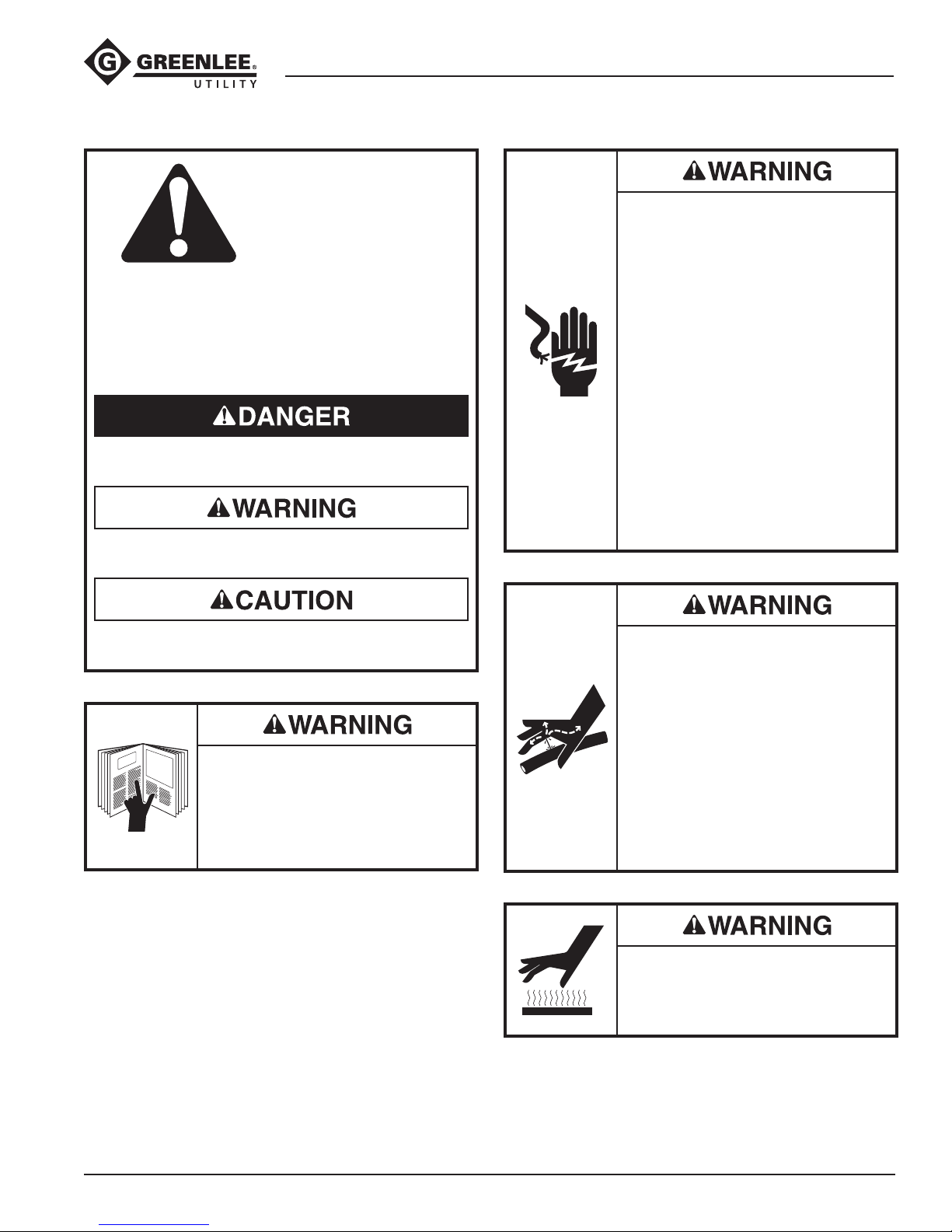
This symbol is used to call your attention to hazards
or unsafe practices which could result in an injury or
property damage. The signal word, dened below,
indicates the severity of the hazard. The message
after the signal word provides information for
preventing or avoiding the hazard.
Immediate hazards which, if not avoided, WILL result
in severe injury or death.
Hazards which, if not avoided, COULD result in
severe injury or death.
43180 Overhead Circular Saw
Electric shock hazard:
• This tool was tested to meet
OSHA 1910.269 (dry test) when
manufactured. It must be properly
cleaned and maintained to ensure
continued non-conductive properties. When using this unit near
energized electrical lines, use only
certied non-conductive hoses
and proper personal protective
equipment.
• Keep berglass extension clean
and dry when working around
energized electrical lines.
Accumulated oil, dirt, and moisture
increase the conductive properties
of the tool.
Failure to observe these warnings
could result in severe injury or death.
Hazards or unsafe practices which, if not avoided,
MAY result in injury or property damage.
Read and understand all of the
instructions and safety information
in this manual before operating or
servicing this tool.
Failure to observe this warning could
result in severe injury or death.
Skin injection hazard:
• Do not use hands to check for
leaks.
• Do not hold hose or couplers while
the hydraulic system is pressurized.
• Depressurize the hydraulic system
before servicing.
Oil under pressure easily punc-
tures skin, causing serious injury,
gangrene, or death. If you are injured
by escaping oil, seek medical atten-
tion immediately.
Burn hazard:
Tool motor and blade may be hot
during and after operation. Hot
surfaces could cause serious burns.
Greenlee / A Textron Company 4455 Boeing Dr. • Rockford, IL 61109-2988 USA • 815-397-7070
3
Page 4
43180 Overhead Circular Saw
IMPORTANT SAFETY INFORMATION
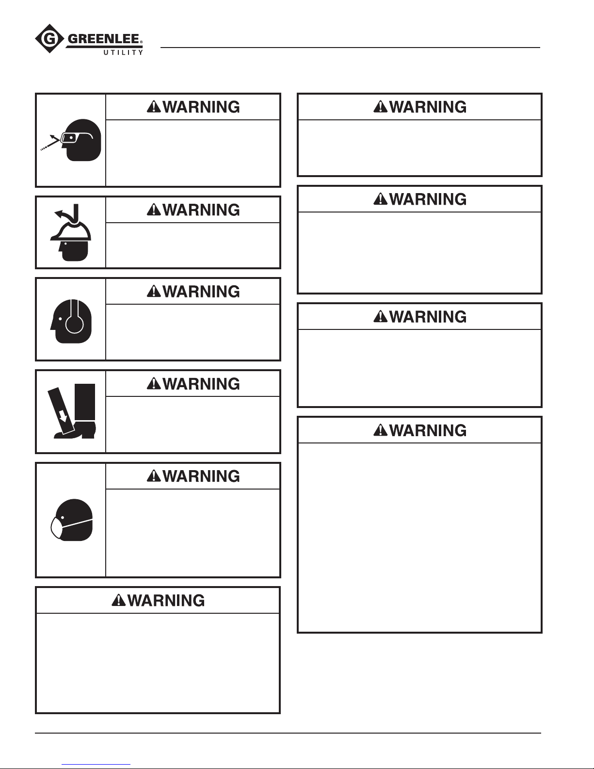
Wear eye protection when operating
or servicing this tool.
Failure to wear eye protection could
result in serious eye injury from ying
debris or hydraulic oil.
Wear a hard hat when using this tool.
Failure to observe this warning could
result in severe injury or death.
Wear hearing protection when using
this tool.
Long-term exposure to high noise
levels could result in hearing loss.
Wear foot protection when using this
tool.
Failure to observe this warning could
result in serious injury.
Some types of timber can produce
hazardous dust when cut. Wear
a dust mask to prevent breathing
hazardous dust.
Failure to observe this warning could
result in temporary breathing difculty or serious injury.
Do not exceed the following hydraulic power source
maximums:
• Hydraulic ow: 22.7 l/min (6 gpm)
• Pressure relief: 138 bar (2000 psi)
• Back pressure: 13.8 bar (200 psi)
Failure to observe this warning could result in severe
injury or death.
Burn hazard:
Do not disconnect tool, hoses, or ttings while the
power source is running or if the hydraulic uid is
hot. Hot hydraulic uid could cause serious burns.
Cutting hazard:
The saw blade continues to rotate after the trigger
is released. Do not retract or lay the saw down until
blade stops moving.
Failure to observe this warning could result in severe
injury or death.
Do not reverse hydraulic ow. Operation with
hydraulic ow reversed can cause tool malfunction.
Connect the pressure (supply) hose and tank (return)
hose to the proper ports.
Failure to observe this warning could result in severe
injury or death.
• Do not change accessories, inspect, adjust, or
clean tool when it is connected to a power source.
Accidental start-up can result in serious injury.
• Maintain a rm grip on tool, using both hands at all
times. Serious injury can result if an operator does
not control the tool.
• Do not lock trigger in the Power-ON position.
Operator cannot stop tool when trigger is locked.
• Do not remove or modify tool’s safety trigger.
Accidental start-up can result in serious injury.
• Always wear protective gloves when handling or
adjusting the blade. The blade can cut even when
stationary.
Failure to observe these warnings could result in
severe injury or death.
Greenlee / A Textron Company 4455 Boeing Dr. • Rockford, IL 61109-2988 USA • 815-397-7070
4
Page 5
43180 Overhead Circular Saw
IMPORTANT SAFETY INFORMATION
• Always use blades that meet applicable industrial
safety code specications.
• Always use blades rated for 5400 rpm or higher.
• Blade must be installed to rotate correctly.
Refer to the Illustrations and Parts Lists and blade
manufacturer’s instructions. An improperly installed
blade could result in injury.
• Inspect blades before installing and before operating. Do not use a damaged or worn blade.
A damaged blade can break and injure nearby
personnel. Destroy the blade if cracks, chips,
gouges, or loose or missing teeth are evident.
Failure to observe these warnings could result in
severe injury or death.
Hydraulic oil can cause skin irritation.
• Handle the tool and hoses with care to prevent
skin contact with hydraulic oil.
• In case of accidental skin contact with hydraulic
oil, wash the affected area immediately to remove
the oil.
Failure to observe these precautions may result in
injury.
Procedure for connecting or disconnecting hydraulic
hoses, ttings, or components:
1. Move the ow lever on the hydraulic power
source to the OFF position.
2. Stop the hydraulic power source.
3. Follow the sequence under “Hose Connections”
to prevent pressure buildup. In case some
pressure has built up, loosen hoses, ttings, or
components slowly.
Emergency stop procedure:
1. Release the trigger.
2. Shut off the hydraulic power source.
Note: Keep all decals clean and legible, and replace
when necessary.
• Inspect tool before use. Replace any worn,
damaged, or missing parts. A damaged or
improperly assembled tool can malfunction, injur-
ing nearby personnel.
• Inspect the hydraulic hoses and couplers every
operating day. Repair or replace if leakage, cracking, wear, or damage is evident. Damaged hoses
or couplers can fail, resulting in injury or property
damage.
• Use this tool for manufacturer’s intended purpose
only. Use other than that which is described in this
manual can result in injury or property damage.
• Make sure that all bystanders are clear of the work
area when operating the tool. Nearby personnel
can be injured by ying debris.
Failure to observe these precautions may result in
injury.
Greenlee / A Textron Company 4455 Boeing Dr. • Rockford, IL 61109-2988 USA • 815-397-7070
5
Page 6
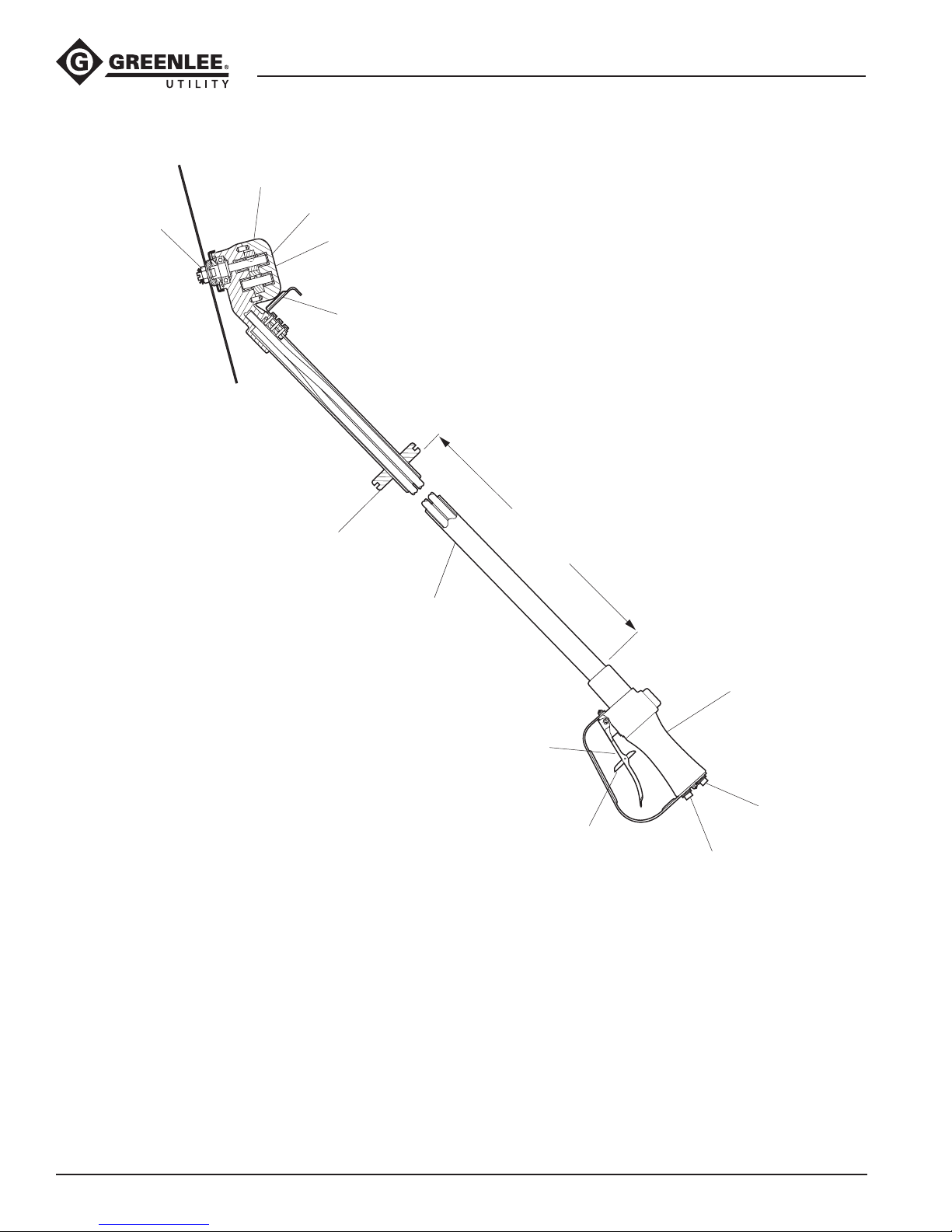
Identification
43180 Overhead Circular Saw
8
10
1
9
7
35 INCHES
6
5
Overhead Circular Saw
1. Serial Number
2. Trigger Handle
3. Trigger Interlock Latch
4. Trigger
5. Fiberglass Extension
6. Rubber Hand Stop
2
4
12
3
11
7. Hook
8. Saw Head
9. Hydraulic Gear Motor
10. Saw Blade
11. Pressure Port P (Supply)
12. Tank Port T (Return)
Greenlee / A Textron Company 4455 Boeing Dr. • Rockford, IL 61109-2988 USA • 815-397-7070
6
Page 7
Specifications
43180 Overhead Circular Saw
Circular Saw
Type of Hydraulic System .........................Open-center or
closed-center
Hydraulic Ports
Pressure ..........................................................3/8 NPT
Return .............................................................3/8 NPT
Mass/Weight (with 9" blade) .......................... 4 kg (8.8 lb)
Length (with 9" blade) ................................. 206 cm (81")
Width (with 9" blade) .................................... 22.9 cm (9")
Blade Diameter Capacity (maximum) ........... 22.9 cm (9")
Cutting Depth (with 9" blade) ...................... 89 mm (3.5")
Revolutions per Minute
@ 15.1 l/min (4 gpm) ............................................ 3571
@ 18.9 l/min (5 gpm) ............................................ 4464
@ 22.7 l/min (6 gpm) ............................................ 5357
Blades
• Always use blades that meet applicable industrial
safety code specications.
• Always use blades rated for 5400 rpm or higher.
• Blade must be installed to rotate correctly.
Refer to the Illustrations and Parts Lists and blade
manufacturer’s instructions. An improperly installed
blade could result in injury.
• Inspect blades before installing and before operating. Do not use a damaged or worn blade.
A damaged blade can break and injure nearby
personnel. Destroy the blade if cracks, chips,
gouges, or loose or missing teeth are evident.
Failure to observe these warnings could result in
severe injury or death.
A 9" blade, rated at 7500 rpm, is furnished with the tool.
Replacement blades are available from Greenlee Utility
as repair parts. Contact an authorized Greenlee Utility
distributor. Any blade used with this tool must meet the
following requirements:
Blade Diameter (maximum) .......................... 22.9 cm (9")
Blade Thickness ....................................... 1.6 mm (1/16")
(nominal)
Arbor Hole Diameter ......................... 16.1 mm x 22.3 mm
(0.635" x 0.878")
Rated Operating rpm (minimum) .............................5400
Greenlee / A Textron Company 4455 Boeing Dr. • Rockford, IL 61109-2988 USA • 815-397-7070
7
Page 8
Specifications (cont’d)
43180 Overhead Circular Saw
Hydraulic Power Source
Do not exceed the following hydraulic power source
maximums:
• Hydraulic ow: 22.7 l/min (6 gpm)
• Pressure relief: 138 bar (2000 psi)
• Back pressure: 13.8 bar (200 psi)
Failure to observe this warning could result in severe
injury or death.
Type of Hydraulic System ........................ Open-center or
closed-center
Flow
Minimum ......................................... 15.1 l/min (4 gpm)
Recommended ...............................18.9 l/min (5 gpm)
Maximum ........................................ 22.7 l/min (6 gpm)
Filtration ............................................ 10 micron (nominal)
Operating Pressure
Minimum ......................................... 121 bar (1750 psi)
Maximum ........................................ 138 bar (2000 psi)
Pressure Relief Setting ........................ 138 bar (2000 psi)
Back Pressure (maximum)* .................. 13.8 bar (200 psi)
* 13.8 bar (200 psi) is the maximum agreed stan-
dard back pressure for the HTMA (Hydraulic Tool
Manufacturers Association). Greenlee Utility tools will
operate satisfactorily at this standard.
1. Maximum hydraulic uid temperature must not
exceed 60 °C (140 °F). A sufcient oil cooling
capacity is needed to limit the hydraulic uid
temperature.
2. Hydraulic ow must not exceed 22.7 l/min (6 gpm).
Install a ow meter in the return line to measure the
rate of hydraulic ow before using the tool.
3. Pressure relief valve setting must not exceed
138 bar (2000 psi) at the tool’s maximum ow.
Locate the pressure relief valve in the supply circuit
to limit excessive hydraulic pressure to the tool.
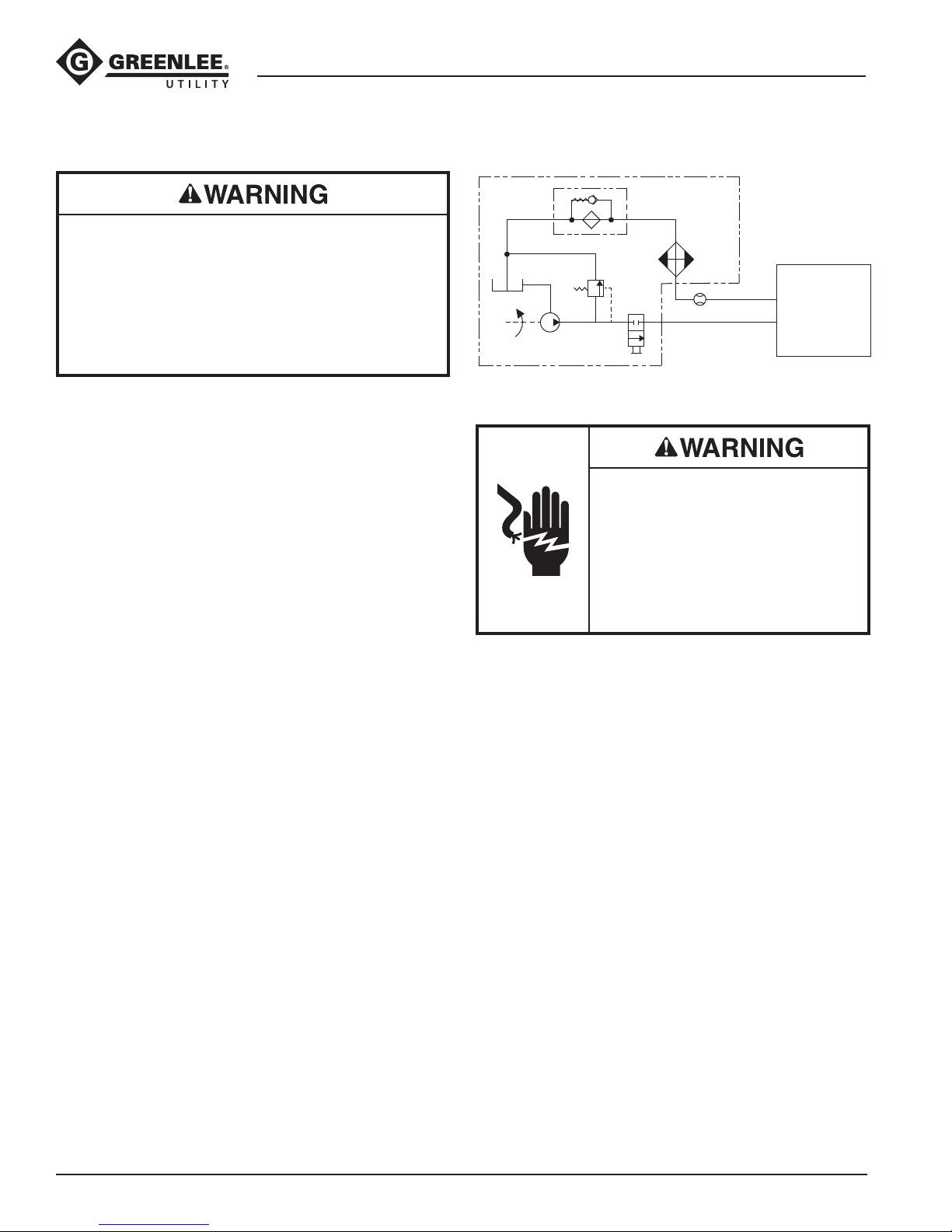
Hydraulic Schematic
FILTER
(10 micron)
RESERVOIR
PUMP
POWER SOURCE
RELIEF
VALVE
138 bar
(2000 psi)
CONTROL
VALVE
COOLER
FLOW METER
T
P
TOOL
Recommended Hydraulic Fluids
Electric shock hazard:
When using this tool near energized electrical lines, select and
maintain the hydraulic uid to meet
the minimum dielectric standards
required by your safety department.
Failure to observe this warning could
result in severe injury or death.
Use any non-detergent, petroleum-based hydraulic
uid which meets the following specications or HTMA
specications.
S.U.S. @
38 °C (100 °F) .............................................140 to 225
99 °C (210 °F) ..........................................40 minimum
Flash Point ................................170 °C (340 °F) minimum
Pour Point ................................. –34 °C (–30 °F) minimum
Greenlee / A Textron Company 4455 Boeing Dr. • Rockford, IL 61109-2988 USA • 815-397-7070
8
Page 9
43180 Overhead Circular Saw
Hoses and Fittings
Installation and Maintenance
Refer to publication 99930323, SAE J1273
(Hose and Hose Assemblies).
Replacement
Refer to a Greenlee Utility catalog or publication
99910322, Low Pressure Quick Couplers, Adapters,
and Hoses.
Burn hazard:
Do not disconnect tool, hoses, or ttings while the
power source is running or if the hydraulic uid is
hot. Hot hydraulic uid could cause serious burns.
Hose Connections
Connecting Hoses
1. Move the ow lever on the hydraulic power source
to the OFF position.
2. Stop the hydraulic power source.
3. Connect the return hose to the return port on the
hydraulic power source, and then to the return port
on the tool.
4. Connect the pressure hose to the pressure port
on the tool, and then to the pressure port on the
hydraulic power source.
Disconnecting Hoses
1. Move the ow lever on the hydraulic power source
to the OFF position.
2. Stop the hydraulic power source.
3. Disconnect the pressure hose from the hydraulic
power source, and then from the tool.
4. Disconnect the return hose from the tool, and then
from the hydraulic power source.
5. Install dust caps over the ports to prevent
contamination.
Greenlee / A Textron Company 4455 Boeing Dr. • Rockford, IL 61109-2988 USA • 815-397-7070
9
Page 10
Blade Removal/Installation
• Do not change accessories, inspect, adjust, or
clean tool when it is connected to a power source.
Accidental start-up can result in serious injury.
• Always wear protective gloves when handling or
adjusting the blade. The blade can cut even when
stationary.
Failure to observe these warnings could result in
severe injury or death.
43180 Overhead Circular Saw
Removing the Blade
Refer to the Illustrations and Parts Lists.
1. Stop power source. Disconnect hydraulic hoses
from power source to tool.
2. Remove cotter key (21).
3. Loosen and remove arbor nut (20). A at blade
screwdriver may be inserted in arbor shaft (6) end
slot to hold shaft when loosening nut. Arbor nut has
left-hand threads. Turn nut clockwise to loosen and
remove.
4. Remove outer ange (19) and blade (18) from arbor
shaft (6).
5. Remove guard (17) and inner ange (16) from arbor
shaft (6).
Tool motor and blade may be hot
during and after operation. Hot
surfaces could cause serious burns.
The saw blade continues to rotate after the trigger
is released. Do not retract or lay the saw down until
blade stops moving.
Failure to observe this warning could result in severe
injury or death.
• Always use blades that meet applicable industrial
safety code specications.
• Always use blades rated for 5400 rpm or higher.
• Blade must be installed to rotate correctly.
Refer to the Illustrations and Parts Lists and blade
manufacturer’s instructions. An improperly installed
blade could result in injury.
• Inspect blades before installing and before
operating. Do not use a damaged or worn blade.
A damaged blade can break and injure nearby
personnel. Destroy the blade if cracks, chips,
gouges, or loose or missing teeth are evident.
Failure to observe these warnings could result in
severe injury or death.
Installing the Blade
Refer to the Illustrations and Parts Lists.
1. Inspect inner ange (16) and guard (17) for gouges,
hairline cracks, and wear. If defective, replace
component. After inspection, install inner ange and
guard on arbor shaft (6).
2. Inspect blade that is to be installed. Destroy blade
if cracks, chips, gouges, or loose or missing tips
are evident.
3. Install blade (18) on arbor shaft (6). Make sure a
directional blade is installed correctly to rotation of
saw blade. Blade rotation is counterclockwise as
viewed from motor side of saw.
4. Inspect outer ange (19) for gouges, hairline cracks,
and wear. If defective, replace component. Install
ange on arbor shaft (6).
5. Thread arbor nut (20) on arbor shaft (6). Tighten nut
securely. A at blade screwdriver may be inserted
in arbor shaft end slot to hold shaft when tightening nut. Arbor nut has left-hand threads. Turn nut
counterclockwise to tighten. Be sure anges are
tightened securely but not too tight to spring anges
and change pressure area. Install cotter pin (21).
Greenlee / A Textron Company 4455 Boeing Dr. • Rockford, IL 61109-2988 USA • 815-397-7070
10
Page 11
Operation
43180 Overhead Circular Saw
Electric shock hazard:
• This tool was tested to meet OSHA
1910.269 (dry test) when manufac-
tured. It must be properly cleaned
and maintained to ensure contin-
ued non-conductive properties.
When using this unit near energized
electrical lines, use only certied
non-conductive hoses and proper
personal protective equipment.
• Keep berglass extension clean and
dry when working around energized
electrical lines.
Accumulated oil, dirt, and moisture
increase the conductive properties
of the tool.
Failure to observe these warnings
could result in severe injury or death.
Do not disconnect tool, hoses, or ttings while the
power source is running or if the hydraulic uid is
hot. Hot hydraulic uid could cause serious burns.
Do not change accessories, inspect, adjust, or
clean tool when it is connected to a power source.
Accidental start-up can result in serious injury.
Failure to observe this warning could result in severe
injury or death.
The saw blade continues to rotate after the trigger
is released. Do not retract or lay the saw down until
blade stops moving.
Failure to observe this warning could result in severe
injury or death.
Do not use this saw for cutting or clearing at ground
level. If the blade contacts the ground or other solid
object, the operator can lose control of the saw and
the blade can shatter. Operator can be injured by
ying debris.
Failure to observe this warning could result in severe
injury or death.
Emergency stop procedure:
1. Release the control lever.
2. Shut off the hydraulic power source.
Pre-Operation
Refer to the “Identication” section.
1. Stop power source.
2. Hand stop (6) must be positioned between saw
head (8) and your hand on fiberglass extension
(5), preferably located 35" from trigger handle (2).
3. Connect hydraulic hoses from power source to tool.
Start power source.
4. It is recommended that power source be allowed to
run (idle) for a few minutes to warm hydraulic reservoir uid. Actuating tool intermittently will reduce
time required to warm uid to an efcient operating
temperature.
5. Always operate newly mounted blades on saw
for one minute to ensure proper blade application before cutting any material.
Operation
Refer to the “Identication” section.
1. Grasp berglass extension (5) with one hand and
trigger handle (2) with your opposite hand.
2. Position saw in approximate area to make the
desired cut.
3. To start saw, move trigger interlock latch (3) and
press (squeeze) trigger (4).
4. Feed rotating blade into work using a straight,
steady, constant pressure. Do not “bump”, jam, or
force blade into work, or twist blade in saw cut.
5. Feed blade through work as fast as possible without
slowing blade in cut. Blades operated at speeds
signicantly below efcient speed or if fed through
cut too slowly will generate excessive heat, resulting
in rapid blade wear and/or blade breakage.
6. To stop saw, release trigger (4).
7. After blade has stopped rotating, lay saw on a at
surface or hang up saw using hook (7).
8. Hook (7) may be used to assist in clearing cut
branches only if blade is not rotating.
Greenlee / A Textron Company 4455 Boeing Dr. • Rockford, IL 61109-2988 USA • 815-397-7070
11
Page 12
Maintenance
Wear eye protection when operating
or servicing this tool.
Failure to wear eye protection could
result in serious eye injury from ying
debris or hydraulic oil.
• Do not change accessories, inspect, adjust, or
clean tool when it is connected to a power source.
Accidental start-up can result in serious injury.
• Inspect blades before installing and before
operating. Do not use a damaged or worn blade.
A damaged blade can break and injure nearby
personnel. Destroy the blade if cracks, chips,
gouges, or loose or missing teeth are evident.
• Blade must be installed to rotate correctly. Refer
to the Illustrations and Parts Lists and blade
manufacturer’s instructions. An improperly installed
blade can result in injury.
• Always wear protective gloves when handling or
adjusting the blade. The blade can cut even when
stationary.
Failure to observe these warnings could result in
severe injury or death.
43180 Overhead Circular Saw
Use this maintenance schedule to maximize the tool’s
service life.
Notes: Keep all decals clean and legible, and replace
when necessary.
When disposing of any components (hydraulic hoses,
hydraulic fluid, worn parts, etc.), do so in accordance
with federal, state, and local laws or ordinances.
Daily
1. Wipe all tool surfaces clean, especially berglass
extension.
2. Inspect blade mounted on saw. Remove and
destroy blade if cracks, chips, gouges, or loose
or missing tips are evident.
3. Inspect the hydraulic hoses and ttings for signs
of leaks, cracks, wear, or damage. Replace if
necessary.
4. Install dust caps over the hydraulic ports when the
tool is disconnected.
Monthly
Perform a thorough inspection of the hydraulic hoses
and ttings as described in publication 99930323,
SAE J1273 (Hose and Hose Assemblies).
Annually
Some organizations require an annual inspection.
Have the tool inspected by a Greenlee Utility Authorized
Service Center.
Greenlee / A Textron Company 4455 Boeing Dr. • Rockford, IL 61109-2988 USA • 815-397-7070
12
Page 13
Troubleshooting
43180 Overhead Circular Saw
Before troubleshooting, determine whether the problem
is in the tool, hoses, or power source. Substitute a tool,
hoses, or power source known to be in good working
order to identify the item that is not operating.
Problem Probable Cause Possible Remedy
Tool inoperative. Tool connected to improper
power source hydraulic system.
No hydraulic uid in system or
uid level low.
Incorrect hydraulic uid viscosity. Use uid viscosity recommended. Refer to
Tool components loose. Tighten component hardware.
Dirt, contaminants, etc., in tool
components.
Tool components worn or
damaged.
If the problem is in the tool, refer to the troubleshooting table below. If the problem is in the power source,
refer to the troubleshooting section of the power source
instruction manual.
Refer to “Specications” for type of
hydraulic system required. Verify power
source hydraulic system.
Check uid level. Fill to FULL mark.
Check system for leaks.
“Recommended Hydraulic Fluids” under
“Specications.”
Disassemble tool and clean components.
Disassemble tool. Replace worn or
damaged components.
Tool operates erratically. Hydraulic uid cold. Viscosity of uid may be too high at start of
tool operation. Allow uid to warm to operating temperature. Actuating tool intermittently
will reduce time required to warm uid to an
efcient operating temperature.
Air in system. Check pump suction line for damage or
loose clamps. Tighten clamps or replace
components if necessary. Fill reservoir.
Tool components sticking or
binding.
Dirt, contaminants, etc., in tool
components.
Tool operates slowly. Power source components not
adjusted correctly.
Hydraulic uid cold. Viscosity of uid may be too high at start of
Check for dirt or gummy deposits. Clean
components. Check for worn or damaged
components. Replace components.
Disassemble tool. Clean components.
Refer to power source operator’s manual for
recommended speed, ow, and pressure
settings.
tool operation. Allow uid to warm to operating temperature. Actuating tool intermittently
will reduce time required to warm uid to an
efcient operating temperature.
Greenlee / A Textron Company 4455 Boeing Dr. • Rockford, IL 61109-2988 USA • 815-397-7070
13
Page 14
43180 Overhead Circular Saw
Troubleshooting (cont’d)
Problem Probable Cause Possible Remedy
Tool operates slowly
(cont’d).
Tool operates too fast. Power source components not
Tool feels too hot. Hydraulic uid level low. Check uid level. Fill to FULL mark. Check
Hydraulic uid level low. Check uid level. Fill to FULL mark.
Check system for leaks.
Hydraulic uid viscosity too heavy. Use uid viscosity recommended. Refer to
“Recommended Hydraulic Fluids” under
“Specications.”
Tool components loose. Tighten component hardware.
Dirt, contaminants, etc., in tool
components.
Tool components worn or
damaged.
adjusted correctly.
Hydraulic uid viscosity too light. Use uid viscosity recommended. Refer to
Disassemble tool. Clean components.
Disassemble tool. Replace worn or
damaged components.
Refer to power source operator’s manual for
recommended speed, ow, and pressure
settings.
system for leaks.
“Recommended Hydraulic Fluids” under
“Specications.”
Hydraulic uid dirty. Drain reservoir, ush and ll with clean uid.
Tool control valve stuck in partial
or open position.
Power source components not
adjusted correctly.
Dirt, contaminants, etc., in tool
components.
Worn or damaged O-rings
or gaskets.
Tool components worn
or damaged.
Tool leaks hydraulic uid. Tool components loose. Tighten component hardware.
Worn or damaged O-rings
or gaskets.
Tool components worn
or damaged.
Free spool so it returns to neutral position.
Refer to power source operator’s manual for
proper adjustment of components (ow).
Disassemble tool. Clean components.
Replace worn or damaged O-rings
or gaskets.
Disassemble tool. Replace worn or
damaged components.
Replace worn or damaged O-rings
or gaskets.
Disassemble tool. Replace worn or
damaged components.
Greenlee / A Textron Company 4455 Boeing Dr. • Rockford, IL 61109-2988 USA • 815-397-7070
14
Page 15
43180 Overhead Circular Saw
Troubleshooting (cont’d)
Problem Probable Cause Possible Remedy
Tool control valve sticks or
works hard.
Tool operates backwards. Hydraulic ow reversed to tool. Reverse ow to tool. Check for valve
Tool operates, but blade
does not cut.
Check for dirt or gummy deposits. Clean components.
Misalignment or binding of
control linkage.
Valve components worn
or damaged.
Hydraulic pressure and return lines
connected to opposite tool ports.
Tool components assembled
incorrectly.
Blade loose, spinning on
arbor shaft.
Blade installed opposite to
manufacturer’s cutting rotation.
Correct alignment. Lubricate linkage joints.
Replace damaged components.
Disassemble valve and replace worn or
damaged components.
in system that has reversed ow.
Check hoses for proper ow.
Disconnect hoses. Reverse couplers.
Reconnect hoses to proper tool ports.
Disassemble tool. Reassemble correctly.
Remove blade. Inspect arbor hole.
Replace blade if necessary. Tighten arbor
nut securely. Refer to “Blade Removal/
Installation.”
Check for correct cutting rotation o blade.
If installed incorrectly, remove and install
correctly.
Power source operates but
tool lacks power.
Blade dull. Remove blade and sharpen, or install a
sharp, new blade.
Valve components worn or
damaged, leaking uid internally
(control spool, sleeve, O-rings,
etc.).
Motor components worn or
damaged, leaking uid internally
(bearings, gears, shafts, keys,
O-rings, gasket, etc.).
Disassemble tool valve. Replace worn or
damaged valve components.
Disassemble tool motor. Replace worn or
damaged motor components.
Greenlee / A Textron Company 4455 Boeing Dr. • Rockford, IL 61109-2988 USA • 815-397-7070
15
Page 16

Disassembly
43180 Overhead Circular Saw
Refer to the Illustrations and Parts Lists.
Complete disassembly of the tool is not recommended.
If a complete overhaul is necessary, return the tool to
your nearest Greenlee Utility Authorized Service Center.
The disassembly procedure is divided into sections of
the tool. Disassemble only the section(s) necessary to
complete the repair.
Note: Remove blade before attempting to disassemble
any components of tool. Refer to “Blade Removal/
Installation.”
Disassemble the tool on a at, clean surface. Take care
not to lose or damage any parts that may fall free during
disassembly.
Inspect all parts as they are disassembled and mating
parts in tool that are not removed for signs of damage,
wear, cracks, etc. Replace any parts which appear to be
damaged.
When removing O-rings which must slide over sharp
surfaces, be careful not to damage the O-rings. Use a
rolling motion, and apply hydraulic uid to ease removal
of O-rings if necessary.
Inner and Outer Tubes
1. Remove hex head cap screw (9) and lock washer (8)
which secure outer tube (7). Remove handle assembly (1) from outer tube (7). Nut carrier (11) may fall
free. Remove inner tubes (4, 5) from ports of handle
assembly (1).
2. Remove three hex head cap screws (15) and lock
washers (14) from motor body (12). The tool hook
(13) can be removed.
3. Pull berglass outer tube (7) and two inner tubes
(4, 5) out of motor body (12), if not removed previously. Nut carrier (11) may fall free. Remove rubber
hand stop safety collar (10), if necessary.
4. Pull two inner tubes (4, 5) out of berglass outer
tube (7).
5. Remove three O-rings (6) twisted in gure eight to
separate the two inner tubes.
Handle Assembly
1. Remove two round head machine screws (13) and
lock washers (14) from guard (12). Remove guard
(12) from handle assembly (1).
2. Remove retaining ring (20) and trigger pivot (19)
which secures trigger (15).
3. Remove internal retaining ring (4) from sleeve
(2) which allows spring (7) and washer (6) to be
removed.
4. Remove internal retaining ring (24) and washer (11).
5. Remove spool (9) from sleeve (2). Remove O-ring
(10) from spool (9).
6. Remove external retaining ring (23). Pull sleeve (2)
out of handle (1). Remove O-rings (3, 5, 8) from
sleeve (2). Remove O-ring (22) from handle (1).
Motor
1. Scribe a line across motor cap (11) and motor body
(1) to align parts correctly during reassembly.
2. Remove eight socket head cap screws (12).
Pull motor cap (11) off motor body (1). Remove
gasket(9).
3. Pull two dowel pins (10) out of motor body, only if
necessary.
4. Pull idler shaft (4) with gear (8) out of motor body.
Remove gear (8) from idler shaft (4). Remove drive
pin (5) from idler shaft.
5. Remove gear (8) and Woodruff key (7) from drive
shaft (6).
6. Remove the internal snap ring (14). Drive shaft (6)
and bearing (13) may be driven out of saw head
assembly, threaded end rst, using a rubber mallet.
Remove bearing (13) from drive shaft (6), only if
necessary.
7. O-ring (2) in motor body may be removed with
needle bearing in place using an O-ring tool.
8. If berglass outer tube and two inner tubes have
been removed, remove the two O-rings (15) from
ports in motor body (1).
Greenlee / A Textron Company 4455 Boeing Dr. • Rockford, IL 61109-2988 USA • 815-397-7070
Needle Bearing Removal
Note: If needle bearings (3) in motor cap (11) or motor
body (1) are damaged or worn, Greenlee Utility recommends replacing the component as an assembly with
bearings already pressed in.
1. Do not remove needle bearings (3) unless they are
damaged or worn. Bearings will be ruined when
they are removed.
2. A blind-hole bearing puller is required to remove
bearings from motor cap or motor body.
16
Page 17

Inspection
43180 Overhead Circular Saw
Refer to the Illustrations and Parts Lists.
Clean all parts with an appropriate cleaning solution
and dry them thoroughly. Inspect each component as
described in this section. Replace any component that
shows wear or damage.
1. Bearing (13): Hold center hub of bearing between
your thumb and index nger. Roll outer surface
against palm of your other hand. Motion should be
smooth with no rough spots. If not, replace bearing.
2. Needle Bearings (3): Hold motor cap or motor body
in one hand, or place on a at surface. Insert drive
shaft or idler shaft in bearing. Spin shaft. Shaft and
bearing should turn smoothly. If not, Greenlee Utility
recommends replacing motor body or motor cap as
an assembly with bearing already pressed in.
3. Motor Body (1) and Motor Cap (11): Mating
surfaces, gear cavities, oil passageways, etc., in
components must be smooth and free of grooves
or nicks. If not, replace component as an assembly
with bearings already pressed in.
4. Drive Shaft (6) and Idler Shaft (4): All surfaces must
be smooth and free of grooves or nicks. If not,
replace component.
5. Spool (9) and Sleeve (2): All surfaces must be
smooth and free of grooves or nicks. If not, replace
component.
6. O-rings: Always replace O-rings in components that
have been disassembled with new O-rings during
assembly. A packing kit is available that includes all
O-rings and gasket.
7. Gasket (9): Always replace gasket when motor cap
is removed from motor body.
Greenlee / A Textron Company 4455 Boeing Dr. • Rockford, IL 61109-2988 USA • 815-397-7070
17
Page 18
Assembly
43180 Overhead Circular Saw
Refer to the Illustrations and Parts Lists for the correct
orientation and placement of parts.
Replace any O-rings, V-rings, seals, and gaskets on
parts that have been disassembled. Apply hydraulic
uid or O-ring lubricant to all O-rings and all metal
surfaces which they must slide over. When installing
an O-ring which must slide over sharp surfaces, use a
rolling motion and be careful not to damage the O-ring.
Wherever the assembly results in metal-to-metal
contact, coat the surfaces with hydraulic uid or
O-ring lubricant.
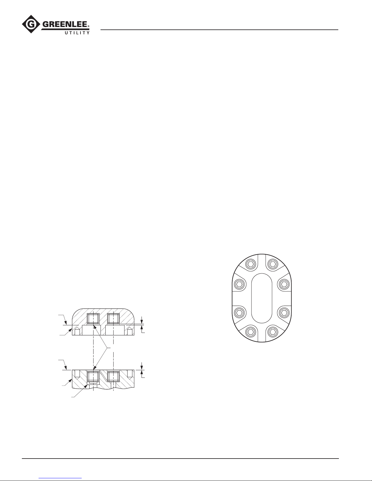
Needle Bearing Installation
Refer to the gure below.
Motor Body:
1. Install a new bearing (2) with identication mark
facing up (readable from Surface A) into motor
body(1).
2. Press bearing into motor body until bearing cage is
0.016" below Surface A.
3. Repeat procedure for the other bearing if it was
removed.
Motor Cap:
1. Install a new bearing (2) with identication mark
facing up (readable from Surface B) into motor
cap(3).
2. Press bearing into motor cap until bearing cage is
0.047" below Surface B.
3. Repeat procedure for the other bearing if it was
removed.
Motor
1. Install new O-ring (2) in motor body drive shaft
opening using an O-ring tool. Be careful not to
damage O-ring during installation.
2. Install two new O-rings (15) in ports of motor
body(1).
3. Press bearing (13) on drive shaft (6). Generously
lubricate drive shaft. Install drive shaft with bearing
in motor body. Press bearing into place. Secure
with a 1-3/8" internal snap ring (14).
4. Install Woodruff key (7) and one gear (8) on drive
shaft (6).
5. Install drive pin (5) in idler shaft (4). Slide one gear
(8) on idler shaft (4). Install idler shaft with gear in
motor body.
6. Install two dowel pins (10) in motor body, if they
were removed. Install gasket (9).
7. Install motor cap (11) on motor body (1), aligning the
scribe marks that were made during disassembly.
8. Secure motor cap using eight socket head cap
screws (12). Torque cap screws to 80 in-lb. Refer to
the gure below for the correct torque sequence.
Torque Sequence
5 7
1
4
Needle Bearing Installation
SURFACE B
(3) MOTOR CAP
NEEDLE BEARING (2)
SURFACE A
(1) MOTOR BODY
O-RING SEAL
Greenlee / A Textron Company 4455 Boeing Dr. • Rockford, IL 61109-2988 USA • 815-397-7070
0.047 BELOW
SURFACE B
0.016 BELOW
SURFACE A
18
3
8 6
2
Page 19

Assembly (cont’d)
43180 Overhead Circular Saw
Handle Assembly
1. Install O-ring (21) in valve handle (1).
2. Install O-rings (22) in valve handle (1). Install O-rings
(3, 5, 8) in sleeve (2). Install sleeve (2) in valve handle
(1). Secure with external retaining ring (23).
3. Install O-ring (10) on spool (9). Install spool (9)
through trigger end of valve handle (1).
4. Install spring (7) and cap (6) and secure with retaining ring (4).
5. Install cap (11) and secure with retaining ring (24).
6. Position trigger (15) onto handle assembly (1). Slide
trigger pivot (19) through holes and secure with
retaining rings (20).
7. Position guard (12) onto handle assembly (1).
Secure with lock washers (14) and round head
machine screws (13).
Inner and Outer Tubes
Note: Inner pressure tube (5) is marked with dye on
both ends for identification during assembly. This inner
pressure tube must be installed in “P” port of both
motor body and valve body. Improper installation of
inner tubes will cause tool to run backwards.
1. Hold the two inner tubes (4, 5) together. Slide one
O-ring (6) over tubes until approximately halfway.
Turn one of the tubes end for end, so that O-ring
forms a gure eight around tubes. Twist one O-ring
(6) in a gure eight and slide over one end of tubes,
locating twisted O-ring approximately 6" from end
of tubes. Repeat twisted O-ring (6) installation for
opposite ends of inner tubes.
2. Lubricate one end of both inner tubes with clean
hydraulic oil to facilitate assembly. Push pressure
inner tube (5) into right pressure port (marked “P”)
of motor body (12). Push return inner tube (4) into
left return port (no mark) of motor body (12).
3. Slide rubber hand stop safety collar (10) on berglass outer tube (7), if removed. Press the nut carrier
(11) into the holes on upper end of berglass outer
tube (7). The nut carrier may be glued to berglass
outer tube to hold it in place during assembly. Slide
berglass outer tube over both inner tubes. Push
berglass outer tube into motor body, aligning nut
carrier inside berglass tube with the holes in motor
body. Apply a drop of Loctite EV sealant, or equivalent, to three hex head cap screws (15). Follow
manufacturer’s recommendations for curing. Install
tool hook (13) to nut carrier inside berglass outer
tube and motor body using three cap screws (15)
and lock washers (14).
4. For proper tool operation, the same inner tube (5)
which was installed in the pressure port of the motor
assembly (12) must be installed in the pressure port
of the handle assembly (1). Lubricate tips of inner
tubes with hydraulic oil to ease assembly. Press
inner tube (5) into the top (return) port of handle
assembly (1). Press inner tube (4) into the lower
(pressure) port, which is marked “P”.
5. Insert plug (3) and O-ring (2) in outer tube (7) and
install in valve handle (1). Secure with cap screw hex
head (9) and washer (8).
Greenlee / A Textron Company 4455 Boeing Dr. • Rockford, IL 61109-2988 USA • 815-397-7070
19
Page 20
43180 Overhead Circular Saw
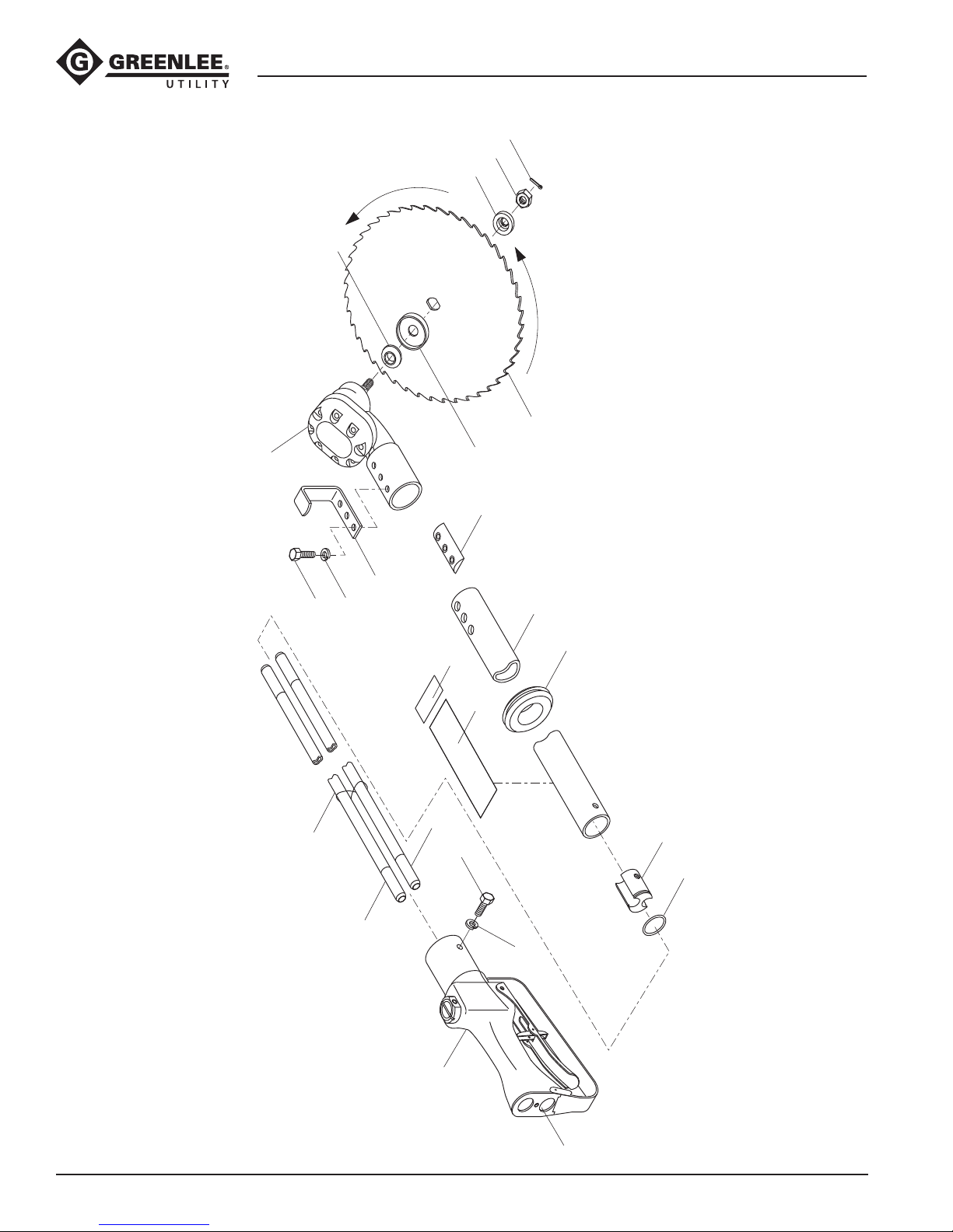
Illustration—43180 Circular Saw
16
12
21
20
19
18
17
11
13
8
9
6
4
Note: Four O-rings (6) are
wrapped in a figure eight
around both tubes and
evenly spaced.
7
10
23
22
5
3
9
2
8
Greenlee / A Textron Company 4455 Boeing Dr. • Rockford, IL 61109-2988 USA • 815-397-7070
1
P
20
Page 21

43180 Overhead Circular Saw
Parts List—43180 Circular Saw
UPC No.
Key 78-3310- Part No. Description Qty
1 48818 50488180 Handle assembly—Model Code FRN
(refer to separate breakdown) ............................................... 1
2* O-ring, 15/16" x 1-1/16" x 1/16" ........................................... 1
3 41121 50411214 Tube plug ............................................................................... 1
4 43394 50433946 Inner tube .............................................................................. 1
5 43395 52015053 Pressure tube ........................................................................ 1
6* O-ring, 7/8" x 1" x 1/16" ........................................................ 4
7 48264 50482645 Outer tube assembly (includes item 22) ................................ 1
8 Lock washer, 1/4" .................................................................. 5
9 Hex head cap screw, 1/4–20 x 3/4", Grade 5 ....................... 5
10 42015 50420154 Grommet ............................................................................... 1
11 40118 50401184 Nut carrier .............................................................................. 1
12 41076 50410762 Motor assembly (refer to separate breakdown)..................... 1
13 40120 50401205 Hook ...................................................................................... 1
16 41192 50411922 Hub washer ........................................................................... 1
17 40127 50401273 Guard ..................................................................................... 1
18 42853 50428530 Saw blade—5/8" arbor .......................................................... 1
†18A 48511 50485113 Saw blade—5/8" arbor and adapter
(includes items 18 and 19) ..................................................... 1
19 41164 50411642 Adapter .................................................................................. 1
20 43396 50433962 Hex nut, M10 x 1.5" LH ......................................................... 1
21 Cotter pin, 1/16" x 1/2" ......................................................... 1
22 46294 50462946 Decal ..................................................................................... 1
23 41547 50415471 Decal ..................................................................................... 1
* 40788 50407881 Packing kit (includes items marked with an asterisk)
41077 50410772 Spacer washer (used with old blade UPC # 40129)
43973 50439731 Chain blade
†Order saw blade (18) if you now have adapter (19).
Greenlee / A Textron Company 4455 Boeing Dr. • Rockford, IL 61109-2988 USA • 815-397-7070
21
Page 22
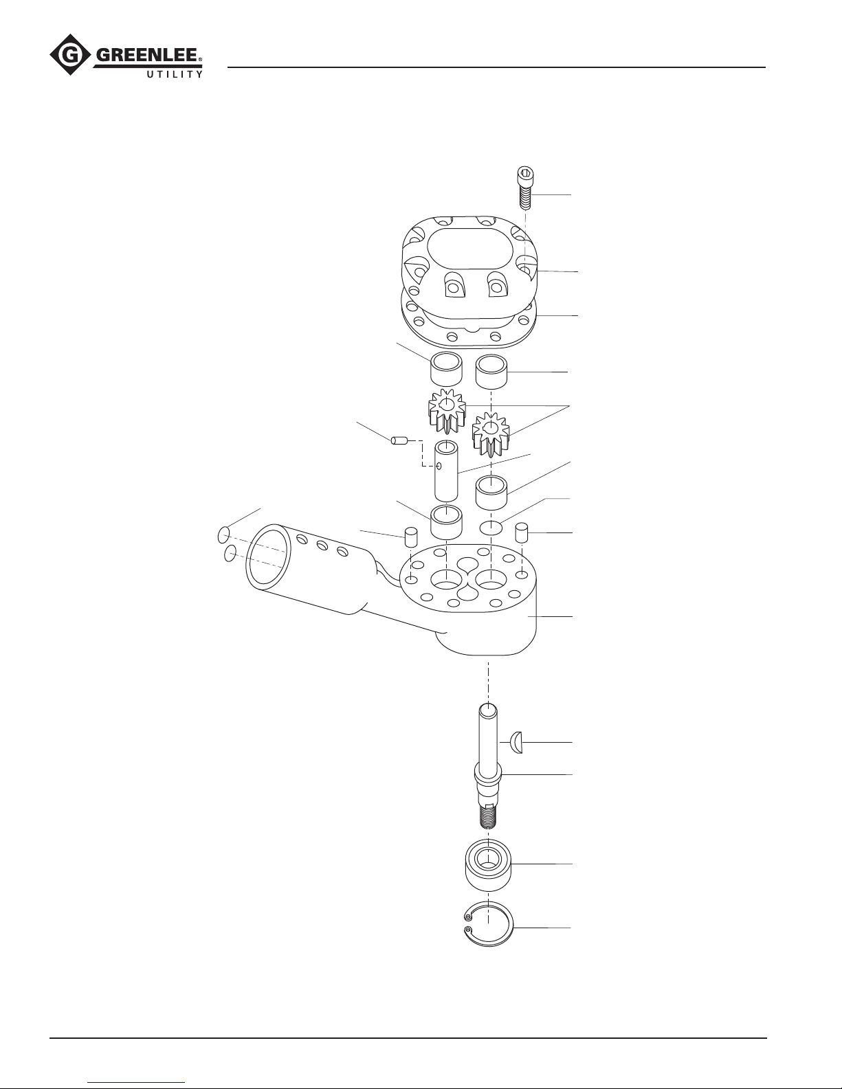
Illustration—Motor Assembly
43180 Overhead Circular Saw
12
11
9
3
3
15
10
5
3
8
4
3
2
10
1
7
6
Greenlee / A Textron Company 4455 Boeing Dr. • Rockford, IL 61109-2988 USA • 815-397-7070
13
14
22
Page 23

43180 Overhead Circular Saw
Parts List—Motor Assembly
UPC No.
Key 78-3310- Part No. Description Qty
41076 50410762 Motor assembly (includes items 1–15) .................................. 1
1 43403 50434039 Body assembly (includes items 2 and 3) ............................... 1
2* O-ring .................................................................................... 1
3 Bearing .................................................................................. 4
4 40168 50401682 Idler shaft ............................................................................... 1
5 41593 50415930 Drive pin ................................................................................ 1
6 41078 50410782 Shaft ...................................................................................... 1
7 41592 50415921 Key ........................................................................................ 1
8 41630 50416302 11-tooth gear ......................................................................... 2
9* Gasket ................................................................................... 1
10 41596 50415960 Dowel pin ............................................................................... 2
11 40412 50404124 Motor cap (includes item 3) ................................................... 1
12 Socket head cap screw, #10–32 x 3/8" ................................. 8
13 41598 50415981 Ball bearing ............................................................................ 1
14 41482 50414821 Retaining ring ........................................................................ 1
15* O-ring .................................................................................... 2
* 40788 50407881 Packing kit (includes items marked with an asterisk)
Greenlee / A Textron Company 4455 Boeing Dr. • Rockford, IL 61109-2988 USA • 815-397-7070
23
Page 24
43180 Overhead Circular Saw
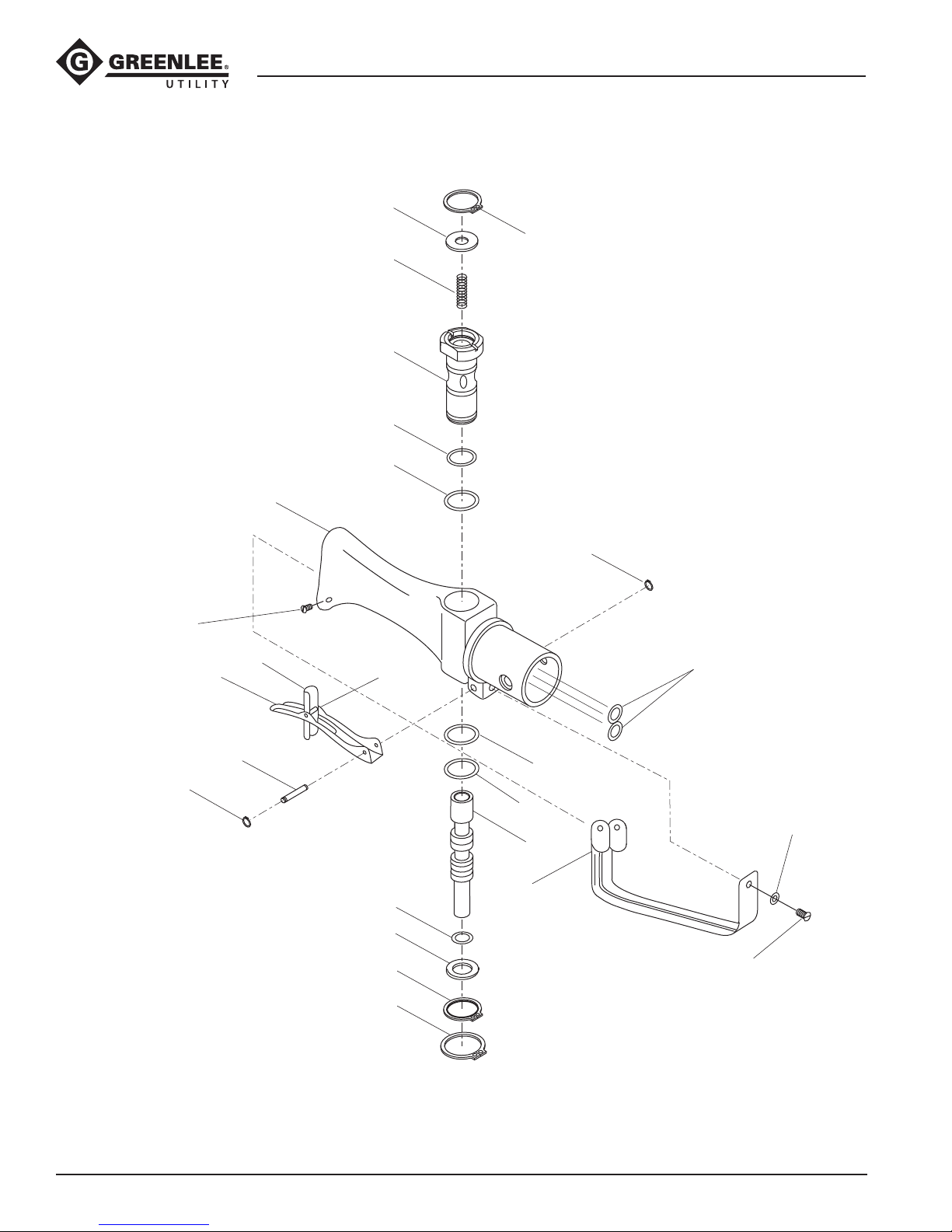
Illustration—Handle Assembly, Model Code FRN
6
4
7
2
8
3
1
20
25
15
19
16
17,18, 20
10
11
24
20
21
5
22
14
9
12
13
Greenlee / A Textron Company 4455 Boeing Dr. • Rockford, IL 61109-2988 USA • 815-397-7070
23
24
Page 25

43180 Overhead Circular Saw
Parts List—Handle Assembly, Model Code FRN
UPC No.
Key 78-3310- Part No. Description Qty
48818 50488180 Handle assembly (includes items 1–25)
1 48815 50488155 Handle ................................................................................... 1
2 43420 50434209 Sleeve .................................................................................... 1
3* O-ring .................................................................................... 1
4 41712 50417122 Retaining ring ........................................................................ 1
5* O-ring .................................................................................... 1
6 41095 50410952 Cap ........................................................................................ 1
7 42865 50428651 Spring .................................................................................... 1
8* O-ring .................................................................................... 1
9 43421 50434217 Spool ..................................................................................... 1
10* O-ring .................................................................................... 1
11 41096 50410962 Washer ................................................................................... 1
12 48817 50488171 Trigger guard ......................................................................... 1
13 Round head machine screw, #10-32 x 3/8............................ 2
14 Lock washer, #10 internal tooth ............................................ 2
04796 50047965 Safety trigger assembly (includes items 15–20)
15 04797 50047973 Trigger .................................................................................... 1
16 04798 50047981 Latch, trigger interlock .......................................................... 1
17 04799 50047990 Spring, torsion ....................................................................... 1
18 04800 50048007 Pin ......................................................................................... 1
19 42547 50425471 Trigger pivot ........................................................................... 1
20 42827 50428270 Retaining ring ........................................................................ 4
21* O-ring .................................................................................... 2
22* O-ring .................................................................................... 1
23 54819 90548191 Retaining ring ........................................................................ 1
24 41297 50412971 Retaining ring ........................................................................ 1
25 Socket button head cap screw, #10-32 x 3/8 ....................... 2
* 40788 50407881 Packing kit (includes items marked with an asterisk)
Greenlee / A Textron Company 4455 Boeing Dr. • Rockford, IL 61109-2988 USA • 815-397-7070
25
Page 26

USA 800-435-0786 Fax: 800-451-2632
815-397-7070 Fax: 815-397-1865
Canada 800-435-0786 Fax: 800-524-2853
International +1-815-397-7070 Fax: +1-815-397-9247
4455 Boeing Drive • Rockford, IL 61109-2988 • USA • 815-397-7070
An ISO 9001 Company • Greenlee Textron Inc. is a subsidiary of Textron Inc.
www.greenlee.com
Printed in USA
 Loading...