

Page 1
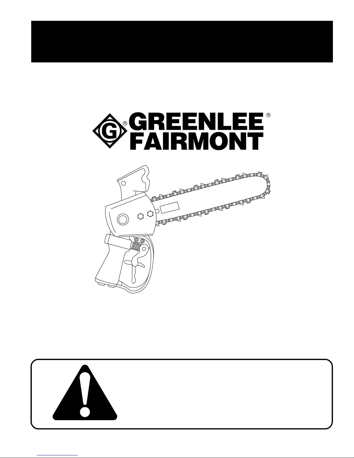
OPERATION, SERVICE AND PARTS
INSTRUCTION MANUAL
TM
Limb-Lopper
by
PISTOL GRIP CHAIN SA W
999 1304.6 REV 2 ©1997 Greenlee Textron 6/97
43179
Read and understand this material before
operating or servicing this tool. Failure to
understand how to safely operate the tool
could result in an accident causing serious
injury or death.
Page 2

GREENLEE
Table of Contents
OPERATION
Safety Information ....................................................................................3-5
Description ..................................................................................................6
Identification ................................................................................................6
Specifications - Chain Saw .........................................................................7
Recommended Hydraulic Fluids ................................................................. 8
Hoses and Fittings.......................................................................................9
Hose Connections .......................................................................................9
Operation..............................................................................................10-13
SERVICE
Maintenance Schedule..............................................................................14
Automatic Chain Oiler ............................................................................... 14
Saw Chain ............................................................................................15-17
Guide Bar ..................................................................................................18
Drive Sprocket and Spacer ....................................................................... 18
Troubleshooting....................................................................................19-22
Disassembly .........................................................................................23-24
Assembly..............................................................................................25-27
PARTS
5043179.0 Chain Saw - Exploded View ................................................... 28
APPENDICES
Appendix A - SAE J1273 May 1986 .....................................................30-31
FAIRMONT
- Saw Chain .........................................................................7
- Hydraulic Power Source .................................................7-8
- Part List..............................................................29
Pistol Grip Chain Saw
Additional or replacement manuals may be obtained from your Greenlee Fairmont distributor. When tool is received,
complete the following record:
SERIAL NUMBER: ____________________________
DATE OF PURCHASE:_________________________
WHERE PURCHASED: ________________________
Always mention the tool’s serial number when ordering or writing about parts.
For convenience in ordering, parts are listed by part number, description and quantity. If in doubt as to part needed,
send a full description, sketch, or the part itself with the order. Assemblies are in CAPITAL letters, and include all
component parts listed directly below them and indented to the right. When assemblies can be used, order them to
save time assembling individual parts. Prior arrangements must be made before returning a tool for warranty service.
To insure correct and prompt shipment of parts, always provide the following information when ordering:
1. Quantity of each part wanted 4. Serial Number of tool
2. Part number of item 5. Preferred method of shipment: by mail, UPS, or air freight
3. Description of part
Greenlee Fairmont Textron / Subsidiary of Textron Inc.
2
4455 Boeing Drive, Rockford, IL 61109 815/397-7070
Page 3
GREENLEE
IMPORTANT SAFETY INSTRUCTIONS
FAIRMONT
Pistol Grip Chain Saw
SAFETY
ALERT
Immediate hazards which, if not avoided, WILL result in
severe personal injury or death.
SYMBOL
The symbol above is used to call your attention
to instructions concerning your personal safety.
Watch for this symbol. It points out important safety
precautions. It means “ATTENTION! Become alert!
Your personal safety is involved!” Read the
message that follows and be alert to the possibility
of personal injury or death.
Safety is a critical factor in the design of Greenlee equipment. The best program starts with a safety-conscious
operator. The information highlighted in this bulletin describes operating practices for the benefit of the workers
who will use our equipment in their daily jobs. Comments from users are appreciated.
A person who has not read and does not understand all
operating instructions is not qualified to operate this tool.
Hazards or unsafe practices which, if not avoided, COULD
result in severe personal injury or death.
Hazards or unsafe practices which, if not avoided, COULD
result in minor personal injury or property damage.
Failure to read and understand safety instructions may
result in injury or death.
Additional copies of this manual are available upon request at no charge.
SA VE THESE INSTRUCTIONS
Greenlee Fairmont Textron / Subsidiary of Textron Inc.
3
4455 Boeing Drive, Rockford, IL 61109 815/397-7070
Page 4
GREENLEE
Safety Information
FAIRMONT
Pistol Grip Chain Saw
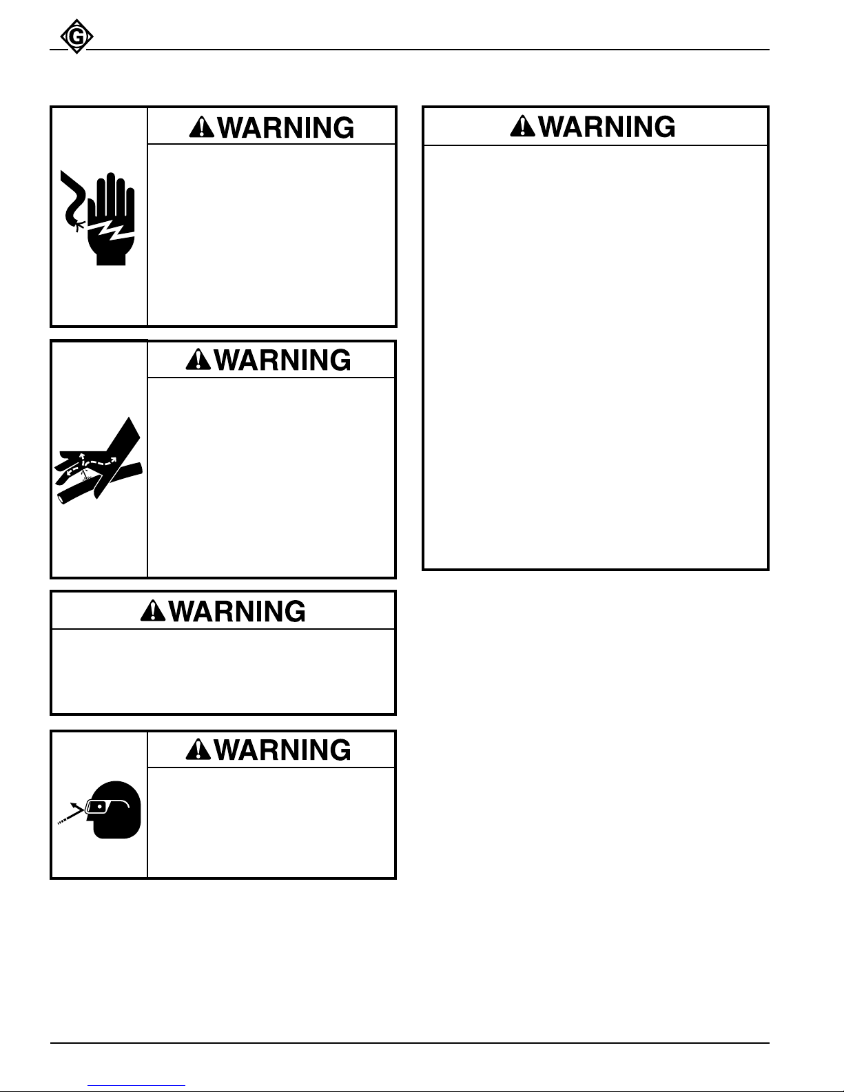
Electrical Shock Hazard:
This tool is not insulated. When
using this unit near energized
electrical lines, use only certified
non-conductive hoses and proper
personal protective equipment.
Failure to observe this warning
could result in severe injury or
death.
Skin Injection Hazard:
High pressure oil easily punctures
skin causing serious injury,
gangrene or death. If injured seek
medical help immediately to remove
oil.
Do not use fingers or hands to
check for leaks.
Depressurize hydraulic system
before servicing.
• Do not change accessories, inspect, adjust or
clean tool when it is connected to a power
source. Accidental start-up can result in
serious injury.
• Maintain a firm grip on tool, using both hands
at all times. Serious injury can result if an
operator does not control the tool.
• Do not lock trigger in the Power-ON position.
Operator cannot stop tool when trigger is
locked.
• Do not remove or modify tool’s two-step safety
trigger. Accidental start-up can result in serious
injury.
• Always disconnect tool from power source
before attempting to adjust or service the chain
saw. Accidental start-up can result in serious
injury.
• Always wear protective gloves when handling
or adjusting the saw chain. The saw chain can
cut even when stationary.
Failure to observe these warnings could result in
severe injury or death.
Do not disconnect tool, hoses or fittings while the
power unit is running or if the hydraulic fluid is hot.
Exposure to hot hydraulic fluid can cause serious
burns.
Wear eye protection when using
this tool.
Failure to wear eye protection can
result in serious eye injury from
flying debris or hydraulic oil.
• Kickback hazard:
Kickback may occur when the moving saw chain
at the nose or tip of the guide bar touches an
object, or when the wood closes in and pinches
the saw chain in the cut. Tip contact in some
cases may cause a lightning-fast reverse
reaction, kicking the guide bar up and back
towards the operator.
• Pushback hazard:
Pinching the saw chain along the top of the
guide bar may push the guide bar rapidly back
towards the operator.
• Do not operate tool with a damaged or worn saw
chain. An improperly sharpened, dull, worn or
damaged saw chain increases the risk of
kickback and pushback.
Failure to observe these warnings could result in
severe injury or death.
Greenlee Fairmont Textron / Subsidiary of Textron Inc.
4
4455 Boeing Drive, Rockford, IL 61109 815/397-7070
Page 5
GREENLEE
Do not reverse hydraulic flow. Operation with
hydraulic flow reversed can cause tool malfunction. Always connect supply (pressure) hose
and return (tank) hose to proper tools ports.
Failure to observe this warning could result in
severe injury or death.
• Use this tool for manufacturer’s intended
purpose only. Use other than that which is
described in this manual can result in injury or
property damage.
• Inspect hydraulic hoses and couplings every
operating day. Repair or replace if leakage,
cracking, wear or damage is evident. Damaged
hoses or couplings can fail resulting in injury or
property damage.
• Make sure all bystanders are clear of the work
area when handling, starting and operating the
tool. Nearby personnel can be injured by flying
or falling debris or by flying parts in the event
of a tool malfunction.
FAIRMONT
Pistol Grip Chain Saw
Failure to observe these precautions could result
in injury or property damage.
Note: Keep all decals clean and legible. Replace
decals when necessary with new decals listed
in the Parts section of this manual.
Greenlee Fairmont Textron / Subsidiary of Textron Inc.
5
4455 Boeing Drive, Rockford, IL 61109 815/397-7070
Page 6
GREENLEE
Description
FAIRMONT
Pistol Grip Chain Saw
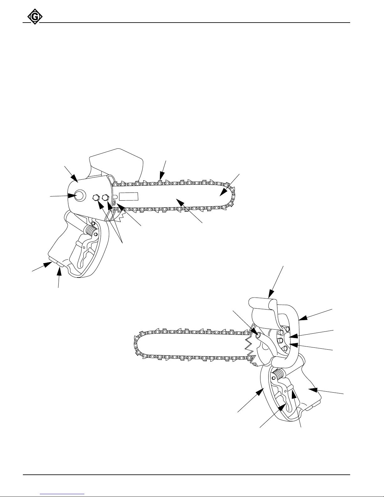
The Pistol Grip Chain Saw is lightweight, compact and
highly maneuverable for tree trimming from an aerial
device or from the ground.
The saw features a rugged, direct-drive gear motor,
13-inch cutting capacity with .325" pitch chain and
Identification
Sprocket Cover Side of Chain Saw
D
G
H
E
automatic oiler. A heat-insulated (PVC-coated) handle
and auxillary handle provide operator comfort. A twostep safety trigger, trigger guard, knuckle guard, and
sprocket cover provide operator protection.
Figure 1
C
B
F
T
Motor Side of Chain Saw
Figure 2
P
PARTS OF THE CHAIN SAW
A. Serial Number J. Trigger Safety Latch
B. Guide Bar K. Trigger Guard
C. Guide Bar Nose L. Saw Handle
D. Saw Chain M. Auxillery Handle
E. Saw Chain Tension Adjustment Screw N. Knuckle Guard
F. Guide Bar Mounting Screws O. Automatic Oiler Metering Screw
G. Sprocket Cover P. Pressure Port P (Supply)
H. Drive Sprocket (inside of sprocket cover) Q. Hydraulic Gear Motor
I. Trigger T. Tank Port T (Return)
N
O
M
A
Q
L
K
I
J
Greenlee Fairmont Textron / Subsidiary of Textron Inc.
6
4455 Boeing Drive, Rockford, IL 61109 815/397-7070
Page 7
GREENLEE
FAIRMONT
Pistol Grip Chain Saw
Specifications - Chain Saw
Length - with Guide Bar...................................................................................22 in. (55.8 cm)
Width..................................................................................................................7 in. (17.8 cm)
Height.........................................................................................................13-1/2 in. (34.3 cm)
Weight - with Guide Bar...................................................................................... 7 lbs. (3.2 kg)
Guide Bar - Cutting Length.................................................................................13 in. (33 cm)
Chain speed - Feet Per Minute@ 4 gpm (15.1 l/m)..............................1814 fpm (552 m/min)
@ 6 gpm (22.7 l/m)..............................2671 fpm (814 m/min)
@ 8 gpm (30.2 l/m)............................3527 fpm (1075 m/min)
Type of Hydraulic System.... Super SpoolTM Selector (for Open- or Closed-Center Operation)
Pressure Port......................................................................... 9/16 in - 18 Female SAE O-Ring
Return Port............................................................................... 3/4 in - 16 Female SAE O-Ring
Saw Chain
• Always use saw chains that meet applicable industrial safety code specifications.
• Always use saw chains rated for 3600 fpm or higher.
Failure to observe these warnings could result in severe injury or death.
A saw chain is furnished with the tool. Replacement saw chains are available from Greenlee
Fairmont as repair parts. CONTACT AUTHORIZED DISTRIBUTOR. Any saw chain used with
this chain saw must meet the following requirements:
Pitch ................................................................................................................................. .325"
Gauge .............................................................................................................................. .058"
Rated Feet Per Minute - Minimum.............................................................................. 3600 fpm
Specifications — Hydraulic Power Source
• Power source flow must not exceed 8 gpm.
• Limit relief pressure to 2000 psi.
Failure to observe these warnings could result in excessive chain speed and over-pressurizing the system,
which could result in severe injury or death.
Any hydraulic power source used with this tool must meet the following requirements:
Type of Hydraulic System ......................................................... Open-Center or Closed Center
Flow - Minimum.............................................................................................. 5 gpm (15.1 l/m)
- Recommended....................................................................................6 gpm (22.7 l/m)
- Maximum............................................................................................. 8 gpm (30.2 l/m)
Operating Pressure - Minimum .................................................................. 1000 psi (69.0 bar)
- Maximum ............................................................... 2000 psi (137.9 bar)
Pressure Relief Setting ............................................................................. 2000 psi (137.9 bar)
Filtration .....................................................................................................10 Micron (Nominal)
Back Pressure - *Maximum........................................................................... 200 psi (13.8 bar)
Greenlee Fairmont Textron / Subsidiary of Textron Inc.
7
4455 Boeing Drive, Rockford, IL 61109 815/397-7070
Page 8
GREENLEE
FAIRMONT
Pistol Grip Chain Saw
Specifications — Hydraulic Power Source (cont’d)
* 200 psi is the maximum agreed standard for the Hydraulic Tool Manufacturers Association (HTMA). Greenlee
Fairmont tools will operate satisfactorily at this standard.
1. Maximum hydraulic fluid temperature must not exceed 140˚F (60˚C) at the maximum expected ambient temperature. A sufficient oil cooling capacity is needed to limit the hydraulic fluid temperature.
2. Maximum hydraulic flow must not exceed 8 gpm @ 2000 psi. A pressure relief valve must be located in the
supply circuit between the pump and tool to limit excessive hydraulic pressure to the tool to 2000 psi.
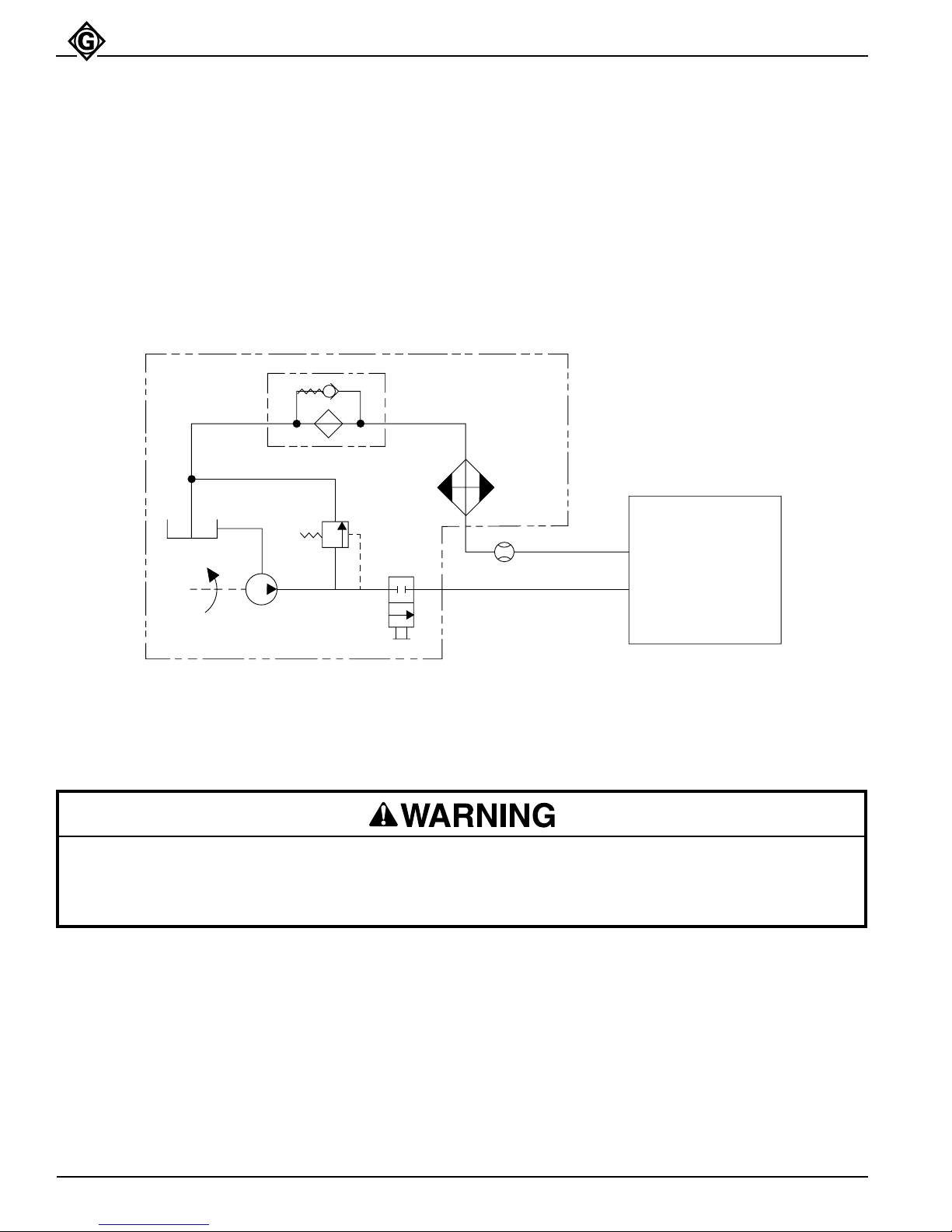
Figure 3 shows a typical power source being used with the tool.
Figure 3
Hydraulic Schematic
FILTER
(10 MICRON)
COOLER
FLOW METER
T
P
TOOL
RESERVOIR
PUMP
POWER SOURCE
RELIEF
VALVE
2000 PSI
CONTROL
VALVE
Recommended Hydraulic Fluids
Electrical shock hazard: Use only hydraulic fluid with dielectric properties when utilizing this tool near energized
electrical lines.
Failure to observe this warning could result in severe injury or death.
Any non-detergent hydraulic fluid which meets the following specifications or HTMA specifications may be used.
S.U.S. @ 100°F (38°C) .........................................................................140 to 225
@ 210°F (99°C) ...................................................................... 40 minimum
Flash Point ...................................................................... 340° F min (170° C min)
Pour Point .........................................................................-30° F min (-34° C min)
Greenlee Fairmont Textron / Subsidiary of Textron Inc.
8
4455 Boeing Drive, Rockford, IL 61109 815/397-7070
Page 9
GREENLEE
FAIRMONT
Pistol Grip Chain Saw
Hoses and Fittings
Hoses and fittings used with this tool must comply
with S.A.E. Standard J1273 (See Appendix A)
recommended practice for selection, installation
and maintenance of hose and hose assemblies.
Failure to observe this standard could result in
severe injury or death.
Hose assemblies and quick connect couplers are
available from Greenlee Fairmont as accessories. See
bulletin on Couplers and Hoses. Contact an authorized
distributor.
Hose Connections
Always stop power source before connecting or
disconnecting tool.
Failure to observe this warning could result in
severe injury or death.
Connecting Hoses (See Figures 1, 2 and 3)
1. STOP THE POWER SOURCE.
2. Connect the return (tank) hose from the power
source (port T) to the tool (port T).
Note: Return (tank) hose connection should always
be connected before supply (pressure) hose
connection to prevent pressure build-up inside
the tool.
3. Connect the supply (pressure) hose from the power
source (port P) to the tool (port P).
Disconnecting Hoses (See Figures 1, 2 and 3)
1. STOP THE POWER SOURCE.
2 Disconnect the supply (pressure) hose from the
power source (port P) to the tool (P port).
Note: Supply (pressure) hose connection should
always be disconnected before return (tank)
hose connection to prevent pressure build-up
inside the tool.
3. Disconnect the return (tank) hose from the power
source (port T) to the tool (port T).
4. To prevent contamination, always install dust caps
over the hydraulic ports of the chain saw when
disconnected.
Greenlee Fairmont Textron / Subsidiary of Textron Inc.
9
4455 Boeing Drive, Rockford, IL 61109 815/397-7070
Page 10
GREENLEE
Operation
FAIRMONT
Pistol Grip Chain Saw
Electrical Shock Hazard:
This tool is not insulated. When
using this unit near energized
electrical lines, use only certified
non-conductive hoses and proper
personal protective equipment.
Failure to observe this warning
could result in severe injury or
death.
Skin Injection Hazard:
High pressure oil easily punctures
skin causing serious injury,
gangrene or death. If injured seek
medical help immediately to remove
oil.
Do not use fingers or hands to
check for leaks.
Depressurize hydraulic system
before servicing.
• Do not change accessories, inspect, adjust or
clean tool when it is connected to a power
source. Accidental start-up can result in
serious injury.
• Maintain a firm grip on tool, using both hands
at all times. Serious injury can result if an
operator does not control the tool.
• Do not lock trigger in the Power-ON position.
Operator cannot stop tool when trigger is
locked.
• Do not remove or modify tool’s two-step safety
trigger. Accidental start-up can result in serious
injury.
• Always disconnect tool from power source
before attempting to adjust or service the chain
saw. Accidental start-up can result in serious
injury.
• Always wear protective gloves when handling
or adjusting the saw chain. The saw chain can
cut even when stationary.
Failure to observe these warnings could result in
severe injury or death.
Do not disconnect tool, hoses or fittings while the
power unit is running or if the hydraulic fluid is hot.
Exposure to hot hydraulic fluid can cause serious
burns.
Wear eye protection when using
this tool.
Failure to wear eye protection can
result in serious eye injury from
flying debris or hydraulic oil.
Greenlee Fairmont Textron / Subsidiary of Textron Inc.
10
4455 Boeing Drive, Rockford, IL 61109 815/397-7070
Page 11
GREENLEE
Operation (cont’d)
FAIRMONT
Pistol Grip Chain Saw
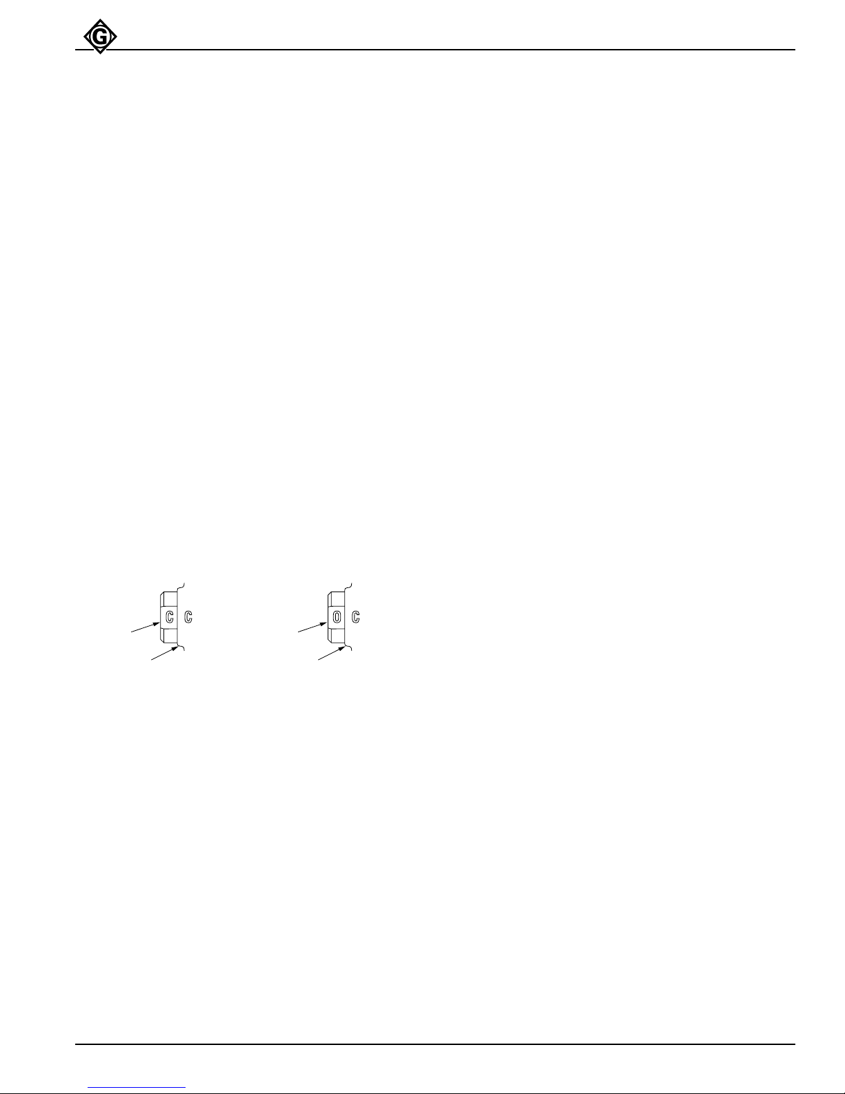
Setting the Super Spool™ Position
(See Figure 4)
The H6200B Chain Saw is equipped with the Greenlee
Fairmont patented Super Spool™ to allow the tool to be
used with either an Open-Center or Closed-Center
hydraulic power system.
Closed-Center Hydraulic System
1. Stop the power source.
2. Turn the Super Spool™ (1) so that the letter “C”,
stamped in the flat of the spool, is aligned with the
letter “C”, stamped in the right side of the tool
handle (2).
Open-Center Hydraulic System
1. Stop the power source.
2. Turn the Super Spool™ (1) so that the letter “O”,
stamped in the flat of the spool, is aligned with the
letter “C”, stamped in the right side of the tool
handle (2).
Figure 4
Setting the Super Spool™ Position
CLOSED - CENTER OPEN - CENTER
1
2
Pre-Operation (See Figures 1 and 2)
1. Stop the power source. Disconnect tool from power
source.
2. Inspect the saw chain. Chain must be properly
sharpened and have no worn or damaged components. AN IMPROPERLY SHARPENED, DULL,
WORN AND/OR DAMAGED CHAIN INCREASES
THE RISK OF KICKBACK.
3. Check the saw chain tension. See Saw Chain
Tension (page 15).
4. Connect the hydraulic hoses from the power source
to the tool. Start the power source.
5. It is recommended that the power source be allowed to run (idle) for a few minutes to warm the
hydraulic reservoir fluid. Actuating the saw intermittently will reduce the time required to warm the fluid
to an efficient operating temperature.
1
2
6. Check the automatic chain oiler. The chain will give
off a fine spray of oil at the guide bar nose if the
oiler is working properly.
7. New saw chains require break-in before cutting any
wood. See New Saw Chain Break-in (page 15).
Operation (See Figures 1 and 2)
1. Grasp the auxiliary handle (13) with your left hand
and the trigger handle (12) with your right hand.
Note: Left-handed operators must follow these hand
placement instructions also.
2.
Position the saw in the area to make the desired cut.
3. To start the saw, move the trigger safety latch (10)
forward and depress (squeeze) trigger (9).
4. Feed the rotating saw chain into the wood using a
steady, constant pressure. DO NOT TWIST THE
GUIDE BAR IN THE SAW CUT. DO NOT BUMP,
JAM OR FORCE GUIDE BAR NOSE INTO THE
WOOD.
5. Feed the saw chain through the wood as fast as
possible without slowing the chain in the cut.
6. To stop the saw, release the trigger (9).
7. AFTER THE SAW CHAIN HAS STOPPED ROTAT–
ING, lay the saw on a flat surface or hang up the
saw.
8. When the chain saw is not in use, stop the power
source to reduce heat and wear on the tool components.
Important
1. Check the automatic oiler setting frequently. Insufficient lubrication can ruin the saw chain and/or guide
bar.
2. Check the saw chain tension frequently, especially
when the saw is initially put into service.
3. Check the fluid level of the power source reservoir
frequently. Fluid level will drop due to the automatic
oiler.
Greenlee Fairmont Textron / Subsidiary of Textron Inc.
11
4455 Boeing Drive, Rockford, IL 61109 815/397-7070
Page 12
GREENLEE
FAIRMONT
Operation
• Kickback hazard:
Kickback may occur when the moving saw chain
at the nose or tip of the guide bar touches an
object, or when the wood closes in and pinches
the saw chain in the cut. Tip contact in some
cases may cause a lightning-fast reverse
reaction, kicking the guide bar up and back
towards the operator.
• Pushback hazard:
Pinching the saw chain along the top of the
guide bar may push the guide bar rapidly back
towards the operator.
• Do not operate tool with a damaged or worn saw
chain. An improperly sharpened, dull, worn or
damaged saw chain increases the risk of
kickback and pushback.
Failure to observe these warnings could result in
severe injury or death.
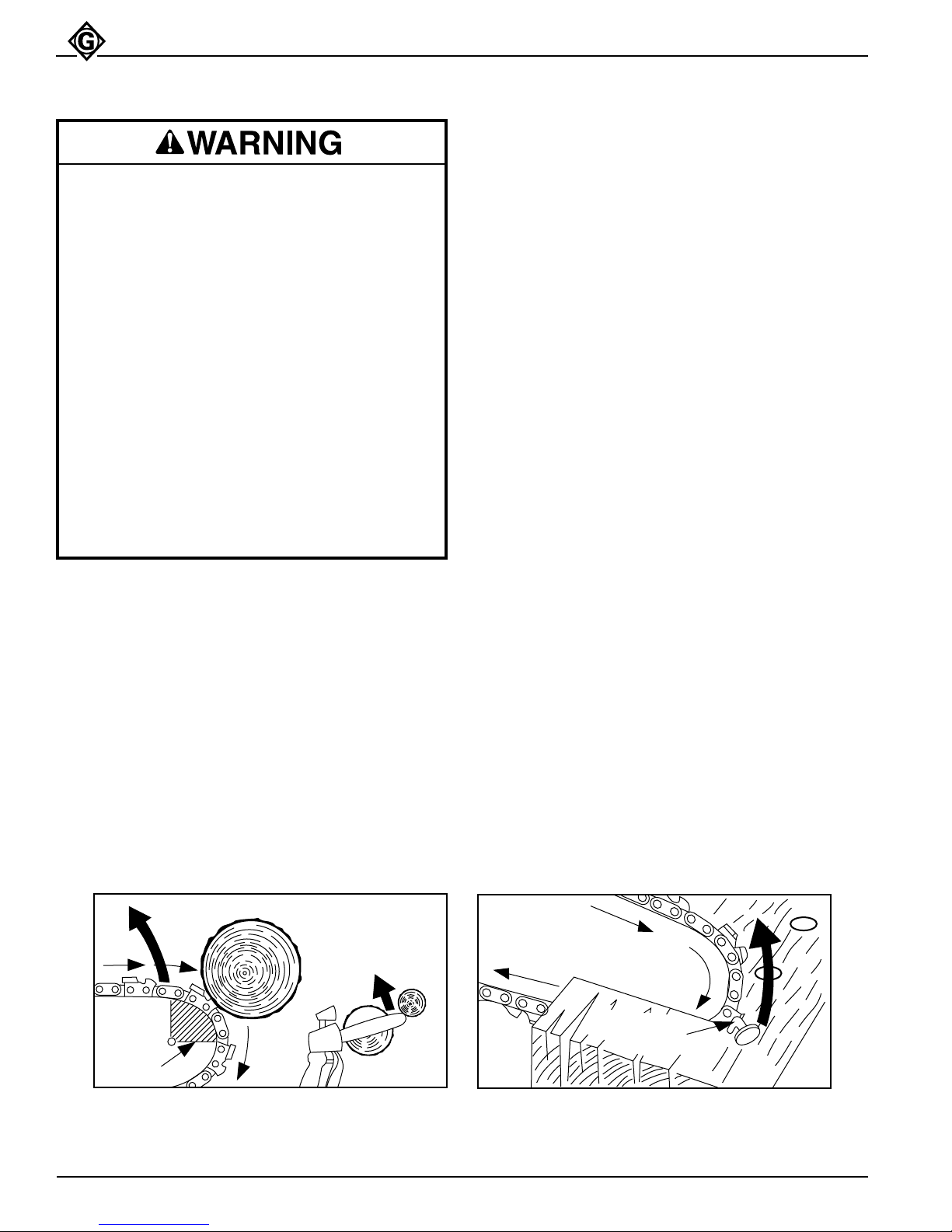
Kickback (See Figures 5 and 6)
Kickback occurs when the upper portion of the guide bar
nose contacts a solid object or is pinched. The reaction
of the cutting force of the chain causes a rotational force
on the chain saw in the direction opposite to the chain
movment. This may fling the bar up and back in an
uncontrolled arc, mainly in the plane of the bar. Under
some cutting circumstances the bar may move violently
towards the operator. Kickback may also occur when
the guide bar nose is pinched, caught, encounters a
foreign object, or is incorrectly used when cutting.
Pistol Grip Chain Saw
Many factors influence the occurrence and force of the
kickback reaction. These include chain speed, the
speed at which the bar and chain contact the object, the
angle of contact, the conditions of the chain, and other
factors.
To Avoid Kickback:
1. Hold the chain saw firmly with both hands and
maintain a firm, secure grip.
2. Be aware of the location of the guide bar nose at all
times.
3. Do not let the guide bar nose contact any object. Do
not cut limbs with the guide bar nose. Be especially
careful when cutting small, tough limbs, small size
brush and saplings which may easily catch the saw
chain.
4. Do not overreach to cut.
5. Do not cut above shoulder height.
6. Always begin and continue the cut at full chain
speed.
7. Cut only one limb at a time.
8. Use extreme caution when re-entering a previous
cut.
9. Be alert for the shifting of the limb or other forces
that may cause the cut to close and pinch the saw
chain.
10. Maintain the saw chain properly. Always cut with a
properly sharpened saw chain and maintain proper
saw chain tension at all times.
11. Always stand to the side of the cutting path of the
saw chain.
Figure 5
Kickback
DANGER
ZONE
Greenlee Fairmont Textron / Subsidiary of Textron Inc.
12
Figure 6
Kickback
METAL
OBJECTS
4455 Boeing Drive, Rockford, IL 61109 815/397-7070
Page 13
GREENLEE
Operation (cont’d)
FAIRMONT
Pistol Grip Chain Saw
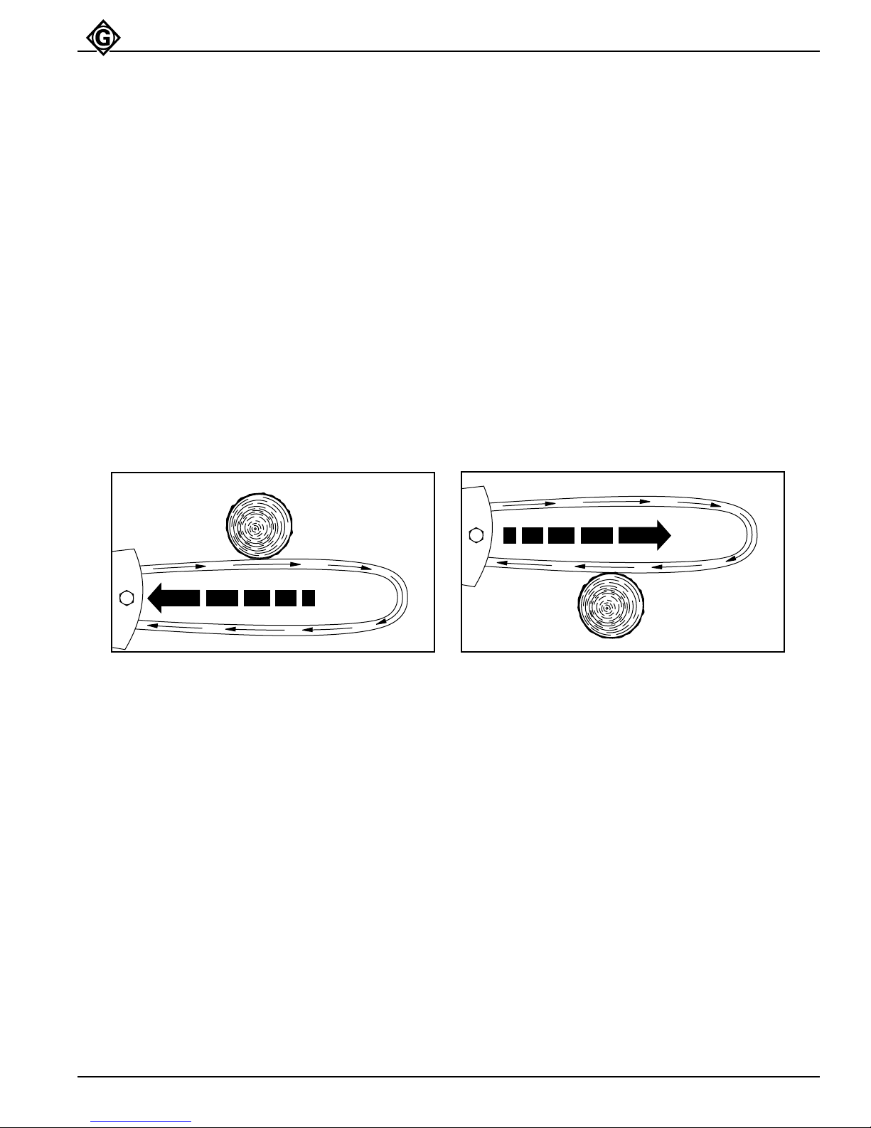
Pushback (See Figure 7)
Pushback occurs when the saw chain on the top of
the guide bar is suddenly stopped by being pinched,
caught or encountering a foreign object in the wood.
The reaction of the chain may push the saw violently
straight back towards the operator. Pushback occurs
when the top of the guide bar is used for cutting.
To Avoid Pushback:
1. Be alert to forces or situations that may cause the
wood to pinch the top of the saw chain.
2. Cut only one limb at a time.
3. Do not twist the saw when withdrawing the guide
bar from the cut.
Figure 7
Pushback
Pull-In (See Figure 8)
Pull-in occurs when the saw chain on the bottom of
the guide bar is suddenly stopped by being pinched,
caught or encountering a foreign object in the wood.
The reaction of the chain may pull the saw violently
forward. Pull-in occurs when the chain is not rotating at
full speed before it contacts the wood.
To Avoid Pull-In:
1. Always begin and continue the cut at full chain
speed.
2. Always begin the cut with the front of the saw head
body in contact with the wood.
Figure 8
Pushback
PUSH
PULL
Greenlee Fairmont Textron / Subsidiary of Textron Inc.
13
4455 Boeing Drive, Rockford, IL 61109 815/397-7070
Page 14
GREENLEE
FAIRMONT
Maintenance Schedule
Pistol Grip Chain Saw
The service life of the chain saw will be maximized by
proper care and maintenance. The maintenance schedule below is recommended.
Inspect saw chain every operating day. Do not
operate tool with a damaged or worn saw chain.
An improperly sharpened, dull, worn or damaged
saw chain increases the risk of kickback and
pushback.
Failure to observe this warning could result in
severe injury or death.
Inspect hydraulic hoses and couplings every
operating day. Repair or replace if leakage,
cracking, wear, or damage is evident. Damaged
hoses or couplings can fail resulting in injury or
property damage.
Chain Saw
Daily:
1. Wipe all saw surfaces clean of grease, dirt and
foreign material.
2. Inspect the saw chain mounted on the saw before
and frequently during use. Chain must be properly
sharpened and have no worn or damaged components. AN IMPROPERLY SHARPENED, DULL
WORN AND/OR DAMAGED CHAIN INCREASES
THE RISK OF KICKBACK.
3. Inspect the hydraulic system hoses and fittings for
signs of leaks, cracks, wear, or damage. Replace if
necessary.
4. Check the saw chain tension before and frequently
during use. Adjust as often as necessary. LOOSE
CHAINS INCREASE THE RISK OF KICKBACK.
5. Check the automatic chain oiler before and frequently during use. The chain will give off a fine
spray of oil at the guide bar nose if the oiler is
working properly. Insufficient lubrication can ruin the
saw chain and/or guide bar.
6. To prevent contamination, always install dust caps
over the hydraulic couplers of the chain saw when
disconnected.
Monthly:
Automatic Chain Oiler
The automatic chain oiler provides a constant supply of
oil to lubricate the guide bar and chain whenever the
saw is operating. A metering screw controls the amount
of oil supplied. The metering screw is preset at the
factory, but may be adjusted to increase or decrease
the oil output volume. Insufficient lubrication can ruin
the saw chain and/or guide bar.
Checking Automatic Oiler Setting
1. Operate the chain saw without cutting any wood.
Notice the guide bar nose while operating.
A. If the saw chain gives off a fine spray of oil, the
oiler is working properly.
B. If the saw chain does not give off a fine spray of
oil, the oiler may need to be adjusted.
Note: Before adjusting the automatic oiler output,
always make sure the oil passage in the base of
the guide bar is cleaned first. If oil drips off the
saw head, sprocket cover and/or base of the bar,
the oil passage in the bar may be plugged.
Adjusting Automatic Oiler Setting
(See Figures 1 and 2)
1. STOP THE POWER SOURCE.
2. Turn the metering screw (15) clockwise to decrease
or counterclockwise to increase oiler output flow.
Limit adjustment to 1/2 turn at a time.
3. Start the power source. Recheck the automatic oiler
setting.
Perform a detailed inspection of the system hoses and
fittings as stated in Appendix A–S.A.E. Standard J1273,
May 1986. Replace the hoses and/or fittings if necessary.
Greenlee Fairmont Textron / Subsidiary of Textron Inc.
14
4455 Boeing Drive, Rockford, IL 61109 815/397-7070
Page 15
GREENLEE
FAIRMONT
Saw Chain
• Do not change accessories, inspect, adjust or
clean tool when it is connected to a power
source. Accidental start-up can result in
serious injury.
• Always disconnect tool from power source
before attempting to adjust or service the chain
saw. Accidental start-up can result in serious
injury.
• Always wear protective gloves when handling
or adjusting the saw chain. The saw chain can
cut even when stationary.
Failure to observe these warnings could result in
severe injury or death.
Saw Chain Tension
Pistol Grip Chain Saw
New Saw Chain Break-in
1. Run the saw at a low chain speed without cutting
any wood for 2 - 3 minutes. Make sure the automatic
oiler is working properly.
2. STOP THE POWER SOURCE. DISCONNECT
TOOL FROM THE POWER SOURCE. Allow the
chain and bar to cool. Check the chain tension and
adjust if necessary.
3. Reconnect tool to the power source. Start the power
source flow. Make a few easy cuts.
4. STOP THE POWER SOURCE. DISCONNECT THE
TOOL FROM THE POWER SOURCE. Allow the
chain and bar to cool. Recheck the chain tension
and adjust if necessary.
5. DO NOT BREAK-IN A NEW SAW CHAIN UNDER
A HEAVY CUTTING LOAD. Check the chain
tension frequently during the first half hour of
cutting.
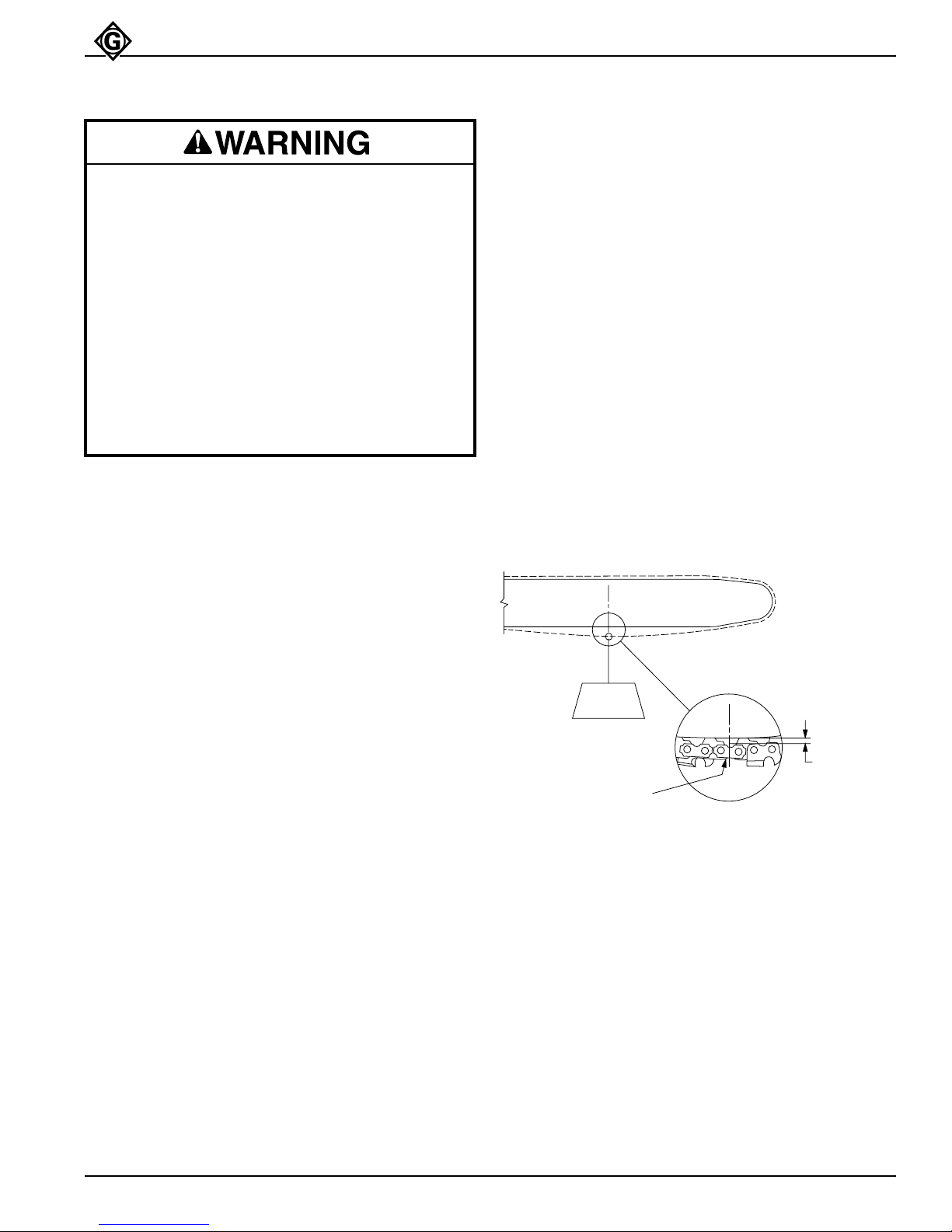
Check the saw chain tension frequently during use and
adjust as often as necessary to keep the chain snug,
but not too tight. The saw chain is properly tensioned
when you can pull the chain around the guide bar easily
and have a 1/8 inch clearance on the bottom of the
guide bar. The saw chain and guide bar should always
be cool when checking and/or adjusting tension.
Checking Tension (See Figure 9)
1. STOP THE POWER SOURCE. DISCONNECT THE
TOOL FROM THE POWER SOURCE.
2. Pull the saw chain around the guide bar. The chain
should pull easily. If it cannot be pulled, it may be
adjusted too tight, bar groove may be damaged,
chain drive links may be damaged, or hydraulic
pressure may be trapped in the saw motor. If there
is pressure in the motor, the hoses were disconnected improperly and the pressure must be
released. See Hose Connection, Disconnecting
Hoses for proper procedure.
3. Pull the saw chain on the bottom of the guide bar
(approximately 2 lb. load). There should be 1/8 inch
(3.2 mm) chain clearance at the center of the bar. If
not, chain tension adjustment is necessary
Saw Chain – Adjusting Tension (See Figures 1 and 2)
1. Loosen the two guide bar mounting screws (6).
2. Turn the saw chain tension adjusting screw (5) until
the proper chain tension is achieved.
3. Hold the guide bar nose (3) up and tighten the two
guide bar mounting screws (6). Torque to 150 inchpounds.
APPROX.
2 LB.
TIE STRAP
Figure 9
Saw Chain Tension
APPROX. 1/8"
Greenlee Fairmont Textron / Subsidiary of Textron Inc.
15
4455 Boeing Drive, Rockford, IL 61109 815/397-7070
Page 16
GREENLEE
FAIRMONT
Pistol Grip Chain Saw
Saw Chain
Saw Chain Sharpening
Note: The saw chain must be sharpened to the manufacturer’s filing specifications. If the saw chain is not properly
filed, the risk of kickback increases. When using a filing guide or hand-held grinder, refer to the manufacturer’s
instructions provided with the unit.
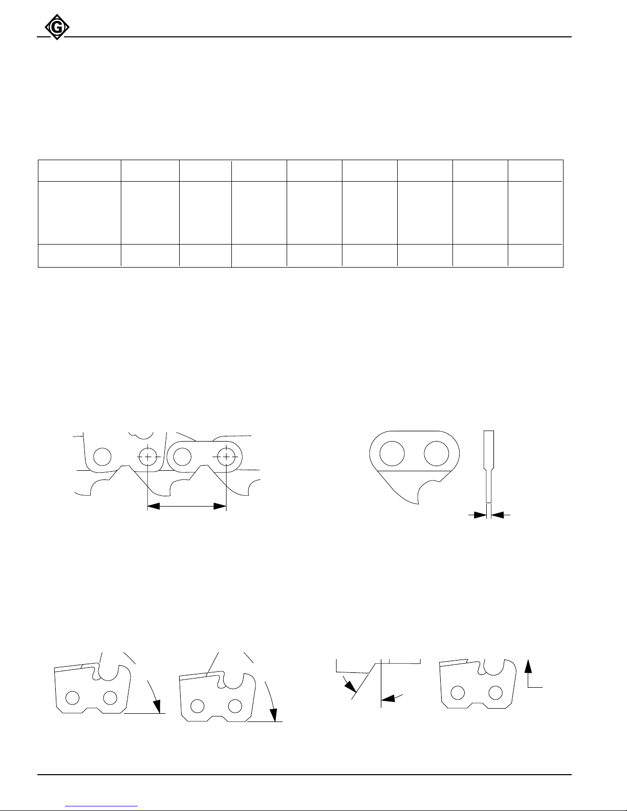
The Pistol Grip Chain Saw is equipped with the following type of saw chain:
See Figure A B C D E F
VENDOR PITCH GAUGE SIDE TOP TOP FILE DEPTH ROUND
PART PLATE PLATE PLATE ANGLE GAUGE FILE
NUMBER FILING CUTTING ANGLE SETTING SIZE
ANGLE ANGLE
Oregon 34SL .325 .058 75° 60˚ 30˚ 10˚ .025 5/32
Saw Chain Pitch
See Figure A. Pitch refers to the saw chain measurement. A chain’s pitch is the distance between any three
of its rivets divided by two. Example: .65 divided by 2
equals .325 pitch.
Figure A
Pitch
THIS DISTANCE
DIVIDED BY TWO
EQUALS PITCH “A”
Figure C Figure D
Side Plate Top Plate
Filing Angle Cutting Angle
Saw Chain Gauge
See Figure B. Gauge refers to the thickness of that
portion of the drive link which fits into the guide bar
groove. The guide bar and saw chain gauge must
match. Industry standards are .050, .058 and .063.
Figure B
Gauge
THICKNESS OF BOTTOM SECTION
OF DRIVE LINK EQUALS GAUGE “B”
Figure E Figure F
Top Plate Depth Gauge
Angle Setting
“C”
Greenlee Fairmont Textron / Subsidiary of Textron Inc.
“D”
16
“F”
“E”
4455 Boeing Drive, Rockford, IL 61109 815/397-7070
Page 17

GREENLEE
Saw Chain
FAIRMONT
Pistol Grip Chain Saw
Filing Depth Gauges
1. If the cutters are sharpened with a file holder, check
and lower the depth gauges before sharpening the
cutters.
2. Check the depth gauges every third sharpening.
3. See Figure 10. Place the depth gauge tool on the
cutter. If the depth gauge projects, file it level with
the top of the tool. Always file from the inside of the
saw chain toward an outside cutter.
Figure 10
Lowering Depth Gauges
4. See Figure 11. Round off the front corner to maintain the original shape of the depth gauge after
using the depth gauge tool. Always follow the
recommended depth gauge setting of the chain
manufacturer. This is important for maximum
performance throughout the saw chain’s life as well
as for protection against kickback.
2. See Figure 13. File the cutters on one side of the
saw chain from the inside out. File on the forward
stroke only.
Figure 13
Filing Cutters
3. See Figure 14. Keep the line on the file holder
parallel to the center of the saw chain. Reverse the
procedure for the other side.
Figure 14
Filing Cutters
FILE HOLDER LINE
Figure 11
Rounding Off Depth Gauges
Filing Cutters - General
1. See Figure 12. Support the file holder on the cutter
top plate and depth gauge as shown.
Figure 12
Filing Cutters
FILE HOLDER
FILE
4. See Figure 15. Keep all cutters the same length.
Figure 15
Filing Cutters
5. See Figure 16. File enough to remove any damage
to the cutting edges (side plate and top plate) of the
cutter.
Figure 16
Filing Cutters
SIDE PLATE TOP PLATE
Greenlee Fairmont Textron / Subsidiary of Textron Inc.
17
4455 Boeing Drive, Rockford, IL 61109 815/397-7070
Page 18
GREENLEE
Service
FAIRMONT
Pistol Grip Chain Saw
Guide Bar
1. The guide bar groove should be cleaned every time
the saw chain is removed or at regular intervals.
This can be done with any instrument small enough
to fit in the groove. Run the instrument along the
groove to remove all the residue.
2. The oil passage in the base of the guide bar should
be cleaned every time the saw chain is removed or
at regular intervals to ensure proper lubrication to
the chain and bar. This can be done with any
instrument small enough to insert into the passage.
Remove all the residue.
3. The guide bar should be turned from top to bottom
every time the saw chain is removed or at regular
intervals to help ensure even guide bar rail and
groove wear.
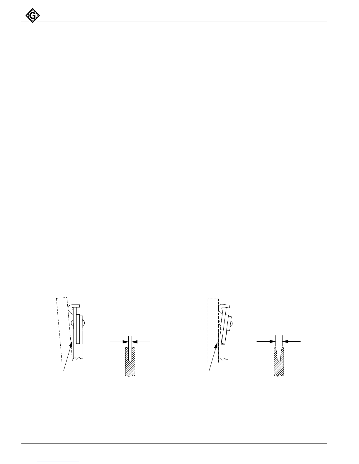
4. The guide bar rails should be checked for wear at
regular intervals.
A. Place a straight edge against the side of the
guide bar and one cutter.
B. If the saw chain is straight and there is clearance
between the guide bar and straight edge, the
guide bar rails are good. See Figure 15.
C. If the saw chain leans and there is no clearance
between the guide bar and straight edge, the
guide bar rails are worn. See Figure 16. Replace
the bar.
Drive Sprocket and Spacer
See Parts illustration. Inspect the drive sprocket and
spacer (29) every time the saw chain is removed or at
regular intervals. A worn drive sprocket and/or spacer
will damage and weaken a saw chain.
Figure 17
Guide Bar Rails Good
STRAIGHTEDGE
CHAIN IS STRAIGHT
CLEARANCE
Greenlee Fairmont Textron / Subsidiary of Textron Inc.
NO CLEARANCE
18
Figure 18
Guide Bar Rails Worn
STRAIGHTEDGE
4455 Boeing Drive, Rockford, IL 61109 815/397-7070
CHAIN LEANS
Page 19

GREENLEE
Troubleshooting
FAIRMONT
Pistol Grip Chain Saw
Before You Begin
1. Tool must be connected to the correct power source
system. See Tool Specifications for the type of
hydraulic system required. Verify the power source
hydraulic system.
2. Verify that the pressure and return hoses are
connected properly to the tool and power source
ports.
3. Power source reservoir must be filled to FULL level
with hydraulic fluid.
4. Start the power source. All power source
shut-off devices must be engaged or opened
(clutch-engaged, separate on/off valves open, etc.).
5. After verifying all of the above, check the tool to see
if it operates.
If the tool does not operate, it will be necessary to
pinpoint the tool, hose or power source as the
problem area. The following steps will help to
determine the problem area.
Determine the Problem Area
1. Stop the power source. Disconnect the existing tool
from the hoses and power source.
2. Connect a known working tool to the hoses and
power source. See the tool’s operator’s manual for
correct hook-up procedure. Start the power source.
If the known working tool operates, the problem is in
the disconnected tool. See the troubleshooting
charts in this operator’s manual.
If the known working tool does not operate, the
problem is likely to be in the hoses or the power
source. Proceed to Step 3.
3. Stop the power source. Disconnect the existing
hoses from the known working tool and power
source.
4. Connect a different set of hoses to the known
operating tool and power source. Start the power
source.
If the known working tool operates with the different
set of hoses, the problem is in the disconnected
hoses.
If the known working tool does not operate, the
problem is in the power source. See your power
source operator’s manual for troubleshooting.
Greenlee Fairmont Textron / Subsidiary of Textron Inc.
19
4455 Boeing Drive, Rockford, IL 61109 815/397-7070
Page 20

GREENLEE
FAIRMONT
Troubleshooting (cont’d)
PROBLEM PROBABLE CAUSE POSSIBLE REMEDY
Pistol Grip Chain Saw
Tool inoperative.
Tool operates erratically.
Tool connected to improper power
source hydraulic system.
No hydraulic fluid in system or fluid
level low.
Incorrect fluid level viscosity.
Tool components loose.
Dirt, contaminants, etc. in tool
components.
Tool components worn or damaged.
Hydraulic fluid cold.
See Tool Specifications for type of
hydraulic system required. Verify
power source hydraulic system.
Check fluid level. Fill to FULL mark.
Check system for leaks.
Use fluid viscosity recommended.
See Recommended Hydraulic
Fluids.
Tighten component hardware.
Disassemble tool and clean
components.
Disassemble tool. Replace worn or
damaged components.
Viscosity of oil may be too high at
start of tool operation. Allow oil to
warm to operating temperature.
Actuating tool intermittently will
reduce time required to warm oil
an efficient operating temperature.
to
Tool operates slowly.
Air in system.
Tool components sticking or
binding.
Dirt, contaminants, etc. in tool
components.
Power source components not
adjusted correctly.
Hydraulic fluid cold.
Check pump suction line for
damage or loose clamps. Tighten
clamps or replace components if
necessary. Fill reservoir.
Check for dirt or gummy deposits.
Clean components. Check for worn
or damaged components. Replace
components.
Disassemble tool. Clean
components.
Refer to power source operator’s
manual for recommended speed,
flow and pressure settings.
Viscosity of oil may be too high at
start of tool operation. Allow oil to
warm to operating temperature.
Actuating tool intermittently will
reduce time required to warm oil to
an efficient operating temperature.
Greenlee Fairmont Textron / Subsidiary of Textron Inc.
20
4455 Boeing Drive, Rockford, IL 61109 815/397-7070
Page 21

GREENLEE
FAIRMONT
Troubleshooting (cont’d)
PROBLEM PROBABLE CAUSE POSSIBLE REMEDY
Pistol Grip Chain Saw
Tool operates slowly. (cont’d)
Tool operates too fast.
Tool feels hot.
Hydraulic fluid level low.
Hydraulic fluid viscosity too heavy.
Tool components loose.
Dirt, contaminants, etc. in tool
components.
Tool components worn or damaged.
Power source components not
adjusted correctly.
Hydraulic fluid level low.
Hydraulic fluid viscosity too light.
Check fluid level. Fill to FULL mark.
Check system for leaks.
Use fluid viscosity recommended.
See Recommended Hydraulic
Fluids.
Tighten component hardware.
Disassemble tool. Clean
components.
Disassemble tool. Replace worn or
damaged components
Refer to power source operator’s
manual for recommended speed,
flow and pressure settings.
Check fluid level. Fill to FULL mark.
Check system for leaks.
Use fluid viscosity recommended.
See Recommended Hydraulic
Fluids.
Tool leaks hydraulic fluid.
Hydraulic fluid dirty.
Tool control valve stuck in partial
Power-ON position.
Power source components not
adjusted correctly.
Dirt, contaminants, etc. in tool
components.
Worn or damaged O-rings or gaskets.
Tool components worn or damaged.
Tool components loose.
Tool components worn or damaged.
Drain reservoir, flush and fill with
clean fluid. Change filter.
Free spool so it returns to neutral
position.
Refer to power source operator’s
manual for recommended speed,
flow and pressure settings.
Disassemble tool. Clean
components.
Replace worn or damaged O-rings
or gaskets.
Disassemble tool. Replace worn or
damaged components.
Tighten component hardware.
Disassemble tool. Replace worn or
damaged components.
Greenlee Fairmont Textron / Subsidiary of Textron Inc.
21
4455 Boeing Drive, Rockford, IL 61109 815/397-7070
Page 22

GREENLEE
FAIRMONT
Troubleshooting (cont’d)
Pistol Grip Chain Saw
PROBLEM
Tool control valve sticks or works
hard.
Tool operates continuously.
Tool operates backwards.
PROBABLE CAUSE
Check for dirt or gummy deposits.
Misalignment or binding of control
linkage.
Valve components worn or
damaged.
Tool control valve stuck in partial
Power-ON position.
Hydraulic flow reversed to tool.
Hydraulic pressure and return lines
connected to opposite tool ports.
Tool components assembled
incorrectly.
POSSIBLE REMEDY
Clean components.
Correct alignment. Lubricate linkage
joints. Replace damaged
components.
Disassemble valve and replace worn
or damaged components.
Free spool so it returns to neutral
position.
Reverse flow to tool. Check for valve
in system that has reversed flow.
Check hoses for proper flow.
Disconnect hoses. Reverse couplers.
Reconnect hoses to proper tool
ports.
Disassemble tool. Reassemble
correctly.
Tool operates, but chain does not
cut.
Power source operates but tool
lacks power.
Chain dull.
Automatic oiler not oiling guide bar
or chain.
Guide bar worn.
Chain improperly installed.
Chain tension adjusted too tight.
Valve components worn or
damaged leaking fluid internally.
Motor components worn or
damaged leaking fluid internally.
Remove chain and sharpen to chain
manufacturer’s specifications or
install a sharp chain.
Check oiler setting. Clean oil ports in
guide bar. Adjust oiler setting if
necessary. See Automatic Chain
Oiler.
Check bar groove and rail wear.
See Guide Bar. If wear is excessive,
replace guide bar.
Remove chain and install correctly.
Check chain tension and adjust if
necessary. See Saw Chain Tension.
Disassemble tool valve. Replace
worn or damaged valve components.
Disassemble tool motor. Replace
worn or damaged motor parts.
Greenlee Fairmont Textron / Subsidiary of Textron Inc.
22
4455 Boeing Drive, Rockford, IL 61109 815/397-7070
Page 23
GREENLEE
Disassembly
FAIRMONT
Pistol Grip Chain Saw
COMPLETE DISASSEMBLY OF THE TOOL IS NOT
RECOMMENDED. RETURN THE TOOL TO YOUR
NEAREST AUTHORIZED GREENLEE FAIRMONT
DISTRIBUTOR OR TO THE FACTORY.
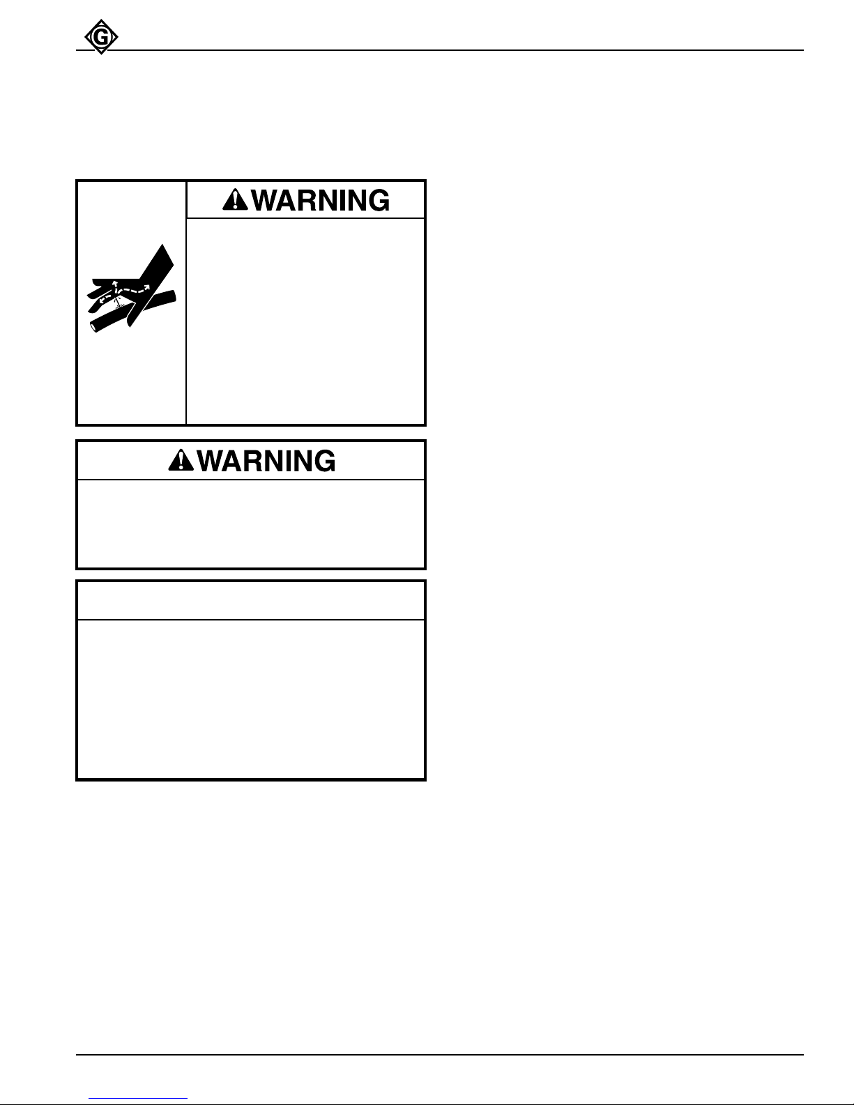
Skin Injection Hazard:
High pressure oil easily punctures
skin causing serious injury,
gangrene or death. If injured seek
medical help immediately to
remove oil.
Do not use fingers or hands to
check for leaks.
Depressurize hydraulic system
before servicing.
Do not disconnect tool, hoses or fittings while the
power unit is running or if the hydraulic fluid is hot.
Exposure to hot hydraulic fluid can cause serious
burns.
IMPORTANT
Procedure for disconnecting tool, removing
hydraulic lines, fittings or components:
1. Stop the power source.
2. Depressurize the hydraulic system.
3. Disconnect hydraulic hoses from tool. Remove
lines, fittings or components slowly to release
any trapped pressure.
The disassembly procedure is divided into sections of
the tool. Complete disassembly of the tool is seldom
necessary. Disassemble only the area(s) necessary to
correct the problem. See Parts illustration for identification of parts as they are removed.
Disassembly should be done on a flat, clean surface.
Some parts may fall free during disassembly. To
prevent part loss or damage, keep the tool as close to
the working surface as possible.
Inspect all parts as they are disassembled and mating
parts in the tool that are not removed for signs of
damage, wear, cracks, etc. Replace any parts which
appear to be damaged.
When removing O-rings which must slide over sharp
surfaces, be careful not to damage the O-rings. Use a
rolling motion, and apply hydraulic fluid to ease removal
of O-rings if necessary.
Saw Chain, Guide Bar and Sprocket Cover
1. Remove the two 1/4 inch hex socket head cap
screws (50) in the sprocket cover (47).
2. Loosen the two 5/16 inch hex head cap screws (49)
in the sprocket cover (47). Turn the 1/4 inch adjusting screw (48) to loosen the chain tension. Remove
the two 5/16 inch cap screws (49).
3. Hold the guide bar (44) and pull the sprocket cover
(47) off the saw head (1).
4. Pull the saw chain (45) off the drive sprocket (41)
and remove the saw chain (45) and guide bar (44).
5. If necessary, remove the 1/4 inch adjusting screw
(48) and dog (46) from the sprocket cover (47).
Drive Sprocket and Spacer
1. Hold the drive sprocket (41) using a spanner
wrench. Loosen and remove the 1/2 inch elastic
stop hex nut (43).
2. Pull the spacer (40) drive sprocket (41), and spacer
(42) off the drive shaft (17). Remove the Woodruff
key (39) from the drive shaft.
Greenlee Fairmont Textron / Subsidiary of Textron Inc.
Auxiliary Handle and Knuckle Guard
1. Remove one 5/16 inch hex flange cap screw (58)
and two external tooth lock washers (57) from the
knuckle guard (56). Remove the knuckle guard from
the auxiliary handle (53).
2. Remove two 1/4 inch hex socket head cap screws
(57) and one #10 hex socket head machine screw
(54) from auxiliary handle (53). Remove the auxiliary handle from the saw head (1).
23
4455 Boeing Drive, Rockford, IL 61109 815/397-7070
Page 24

GREENLEE
Disassembly (cont’d)
FAIRMONT
Pistol Grip Chain Saw
Trigger Guard
1. Remove one #10 x 3/4 inch round head machine
screw (35) and #10 hex elastic stop nut (33) from
the trigger guard (36). Swing the two cover plates
(34) out of the way.
2. Remove one 1/4 x 1/2 inch hex socket head cap
screw (38) and #10 x 1 inch hex socket head
machine screw (37) from the trigger guard (36).
Remove the trigger guard (36) from the saw
head (1).
Trigger
1. Remove one #10 x 3/4 inch round head machine
screw (35) and #10 hex elastic stop nut (33) from
the trigger (26) and two cover plates (34). Remove
the two cover plates.
2. Remove one #10 x 1-1/4 inch round head machine
screw (32) and #10 hex elastic nut (33) from the
trigger (26) and spool (10). Remove the trigger (26),
washer (31) and compression spring (30) from the
spool (10).
3. If necessary, remove one 5/32 x 15/16 inch dowel
pin (29) from the trigger (26). Remove the safety
latch (27) and torsion spring (28) from the trigger.
Control Spool and Sleeve
1. Remove one 5/16 x 3/8 inch button head cap screw
(12) from the control spool (10).
2. Pull the control spool (10) out of the trigger end of
the saw head (1). Remove the O-ring (11) from the
spool.
3. Remove the 7/8 inch external retaining ring (8). Pull
the sleeve (6) out of the saw head (1). Remove the
two O-rings (7 & 9) from the sleeve. Remove the
O-ring (5) from the saw head (1).
4. Remove the gear (21) and Woodruff key (20) from
the drive shaft (17).
5. Remove the 1-3/8 inch internal retaining ring (19).
Remove the drive shaft (17) and bearing (18) from
the bar side of the saw head. Bearing is pressed in.
Remove the bearing (18) from the drive shaft (10),
ONLY IF NECESSARY.
6. Pull the two dowel pins (22) out of the saw head
motor body, ONLY IF NECESSARY.
7. Remove the O-ring (3) in the saw head motor body
(1). The O-ring can be removed with the needle
bearing (4) in place using an O-ring tool.
Needle Bearing Removal
Note: If the needle bearings (4) in the motor cap (13) or
saw head motor body (1) are damaged or worn,
Greenlee Fairmont recommends replacing the
component as an assembly with the bearings
already pressed in.
1. Do not remove the needle bearings (4) unless they
are damaged or worn. Bearings will be ruined when
they are removed.
2. A blind-hole bearing puller is required to remove the
bearings from the motor cap or saw head motor
body.
3. If removed, refer to Figure 20 for proper installation.
Metering Screw
Remove the metering screw (25) from the saw head (1).
Remove the O-ring (24) from the metering screw.
Saw Head and Motor
1. Scribe a line across the motor cap (13) and saw
head motor body (1) to align the parts correctly
during re-assembly.
2. Remove eight 1/4 x 1 inch socket head cap screws
(23). Pull the motor cap (13) from the saw head
motor body (1). Remove the gasket (14).
3. Pull the idler shaft (15) with gear (21) out of the saw
head motor body. Remove the gear (21) from the
idler shaft (15). Remove the drive pin (16) from the
idler shaft, if necessary.
Greenlee Fairmont Textron / Subsidiary of Textron Inc.
24
4455 Boeing Drive, Rockford, IL 61109 815/397-7070
Page 25

GREENLEE
Assembly
FAIRMONT
Pistol Grip Chain Saw
Inspection
1. Bearing (18): Hold the center hub of the bearing
between your thumb and index finger. Roll the outer
surface against the palm of your other hand. Motion
should be smooth with no rough spots. If any
roughness is noted, replace the bearing.
2. Needle Bearings (4): Hold the motor cap or saw
head motor body in one hand, or place on a flat
surface. Insert drive shaft of idler shaft in the
bearing. Spin the shaft. The shaft and bearing
should turn smoothly. If any roughness is noted,
Greenlee Fairmont recommends replacing the saw
head motor body or motor cap as an assembly with
the bearings already pressed in.
3. Saw Head Motor Body (1) and Motor Cap (13):
Mating surfaces, gear cavities, oil passageways,
etc. in the components must be smooth and free of
grooves or nicks. If either component has grooves
or nicks, replace the component as an assembly
with the bearings already pressed in.
4. Drive Shaft (17) and Idler Shaft (15): All surfaces
must be smooth and free of grooves or nicks. If
either component has grooves or nicks, replace the
component.
5. Spool (10) and Sleeve (6): All surfaces must be
smooth and free or grooves or nicks. If either
component has grooves or nicks, replace the
component.
6. O-Rings: Always replace O-rings in components
that have been disassembled with new O-rings
during assembly. A packing kit is available that
includes all O-rings and gasket.
7. Gasket (14): Always replace gasket when motor
cap is removed from saw head motor body.
8. Drive Sprocket (41) and teeth must be not chipped
or broken. If the teeth are worn, all teeth must be
worn equally. If not, replace the sprocket. If the
sprocket teeth are worn and a new saw chain is to
be installed, install a new drive sprocket.
9. Guide Bar (44): Guide bar must be straight. The
rails and groove must not have excessive wear.
If it does, replace the bar.
10. Saw Chain (45): Saw Chain must not have exces-
sive wear, broken or damaged components.
If it does, repair or replace the chain.
Assembly
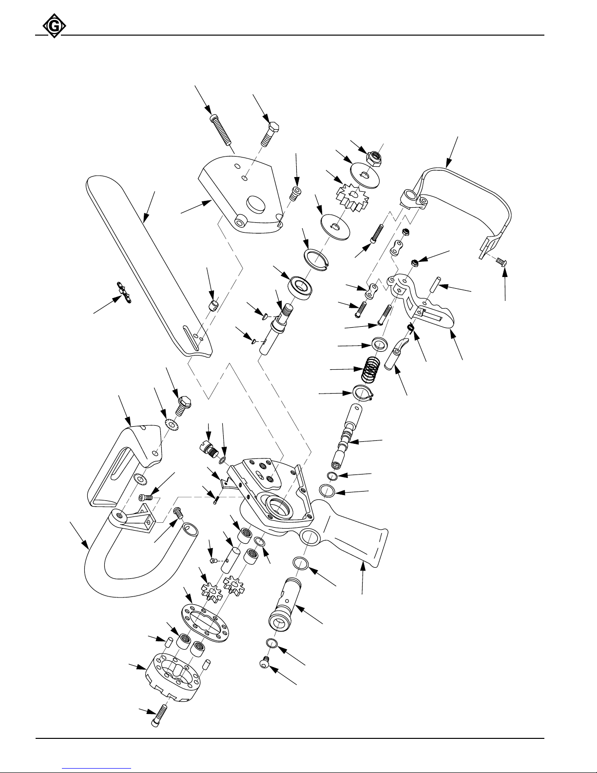
When assembling parts, refer to Parts illustrations
(page 28) for correct orientation and placement of parts.
Clean all parts with solvent, then dry with compressed
air. Do not expose O-rings or other packing components
to solvent for long periods of time.
Inspect all parts as they are assembled for signs of
damage, wear, cracks, etc. Do not install any parts
which appear to be damaged.
Apply clean hydraulic fluid or O-ring lubricant to all
O-rings and all metal surfaces which O-rings must slide
over. When installing an O-ring over a sharp edge, use a
rolling action to avoid damage to the O-ring.
Wherever assembled parts are metal-to-metal contact,
coat the surfaces with clean hydraulic fluid or O-ring
lubricant.
Saw Head and Motor
1. Install a new O-ring (3) in the saw head motor body
(1) using an O-ring tool. Be careful not to damage
the O-ring during installation.
2. Install the two dowel pins (22) in the saw head
motor body, if they were removed. Install the gasket
(14).
3. Press the bearing (18) on the drive shaft (17).
Generously lubricate the drive shaft and install the
drive shaft and bearing in the saw head motor body.
Press the bearing into place. Secure with a 1-3/8
inch internal ring (19).
4. Install the Woodruff key (20) and one gear (21) on
the drive shaft (17).
5. Install the drive pin (16) in the idler shaft, if it was
removed. Slide one gear (21) on the idler shaft (15).
Install the idler shaft with the gear (21) in the saw
head motor body.
6. Install the motor cap (13) on the saw head motor
body (1) aligning the scribe marks that were made
during disassembly.
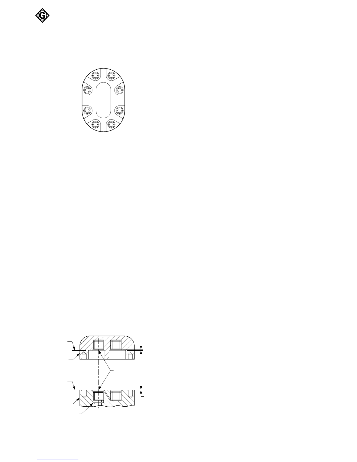
7. Secure the motor cap using eight 1/4 x 1 inch
socket head cap screws (23). Torque the cap
screws to 80 inch-pounds. (See Figure 19 for
torquing sequence.)
Metering Screw
Install a new O-ring (24) on the metering screw (25).
Install the metering screw (25) in the saw head (1).
Greenlee Fairmont Textron / Subsidiary of Textron Inc.
25
4455 Boeing Drive, Rockford, IL 61109 815/397-7070
Page 26

GREENLEE
Assembly (cont’d)
FAIRMONT
Pistol Grip Chain Saw
Control Spool and Sleeve
1. Install a new O-ring (5) in the saw head body (1).
Install two new O-rings (7 & 9) on the sleeve (6).
Install the sleeve (6) in the saw head body (1).
Secure using the 7/8 inch external retaining ring (8).
2. Install a new O-ring (11) on the control spool (10).
Install the control spool (10) through the trigger end
of the saw head body (1).
3. Secure the control spool (10) using one 5/16 x 3/8
inch button head cap screw (12). Apply Locite 242
sealant, or equivalent, to the cap screw. Follow
manufacturer’s instructions for curing.
Trigger
1. Install the safety latch (27) and torsion spring (28) to
the trigger (26) using one 5/32 x 15/16 inch dowel
pin (29), if removed.
2. Install the trigger (26), washer (31) and compression
spring (30) to the control spool (10) using one #10 x
1-1/4 inch round head machine screw (32) and #10
hex elastic stop nut (33).
3. Install the two cover plates (34) to the trigger (26)
using one #10 x 3/4 inch round head machine screw
(35) and #10 hex elastic stop nut (33).
Trigger Guard
1. Install the trigger guard (36) to the saw head body
(1) using one 1/4 x 1/2 inch hex socket head cap
screw (38) and one #10 x 1 inch hex socket head
machine screw (37).
2. Place the two cover plates (34) to align with the hole
in the trigger guard and secure using one #10 x 3/4
inch round head machine screw (35) and #10 hex
elastic stop nut (33).
Drive Sprocket and Spacer
1. Install the Woodruff key (39) in the drive shaft (17).
Install the spacer (40) (small diameter towards
bearing), drive sprocket (41), and spacer (42) on
the drive shaft.
2. Install the 1/2 inch elastic shop hex nut (43) on the
drive shaft (17). Hold the drive sprocket (41) and
tighten the stop nut securely.
Saw Chain, Guide Bar and Sprocket Guard
1. Install the 1/4 inch adjusting screw (48) and dog
(46) in the sprocket cover (36), if removed.
2. Install the saw chain (45) around the guide bar (44)
groove. Position the guide bar with the saw chain on
the saw head body and install the saw chain around
the drive sprocket (41).
3. Align the dog (46) in the sprocket cover (47) with
the hole below the long adjusting slot in the guide
bar (44) and at the same aligning the holes in the
sprocket cover and guide bar with the threaded
holes in the saw head (1). Install two 5/16 x 1-1/4
inch hex head cap screws (49).
4. Install two 1/4 x 1/2 inch hex socket head cap
screws (50) in the sprocket cover (47).
Note: Chain should be snug, but not too tight. To check
tension, gently pull bottom of saw chain away
from saw guide bar (44). Saw chain (45) should
be just loose enough that the saw chain guides
come completely out of the groove in the saw
bar. Turn tension bolt (48) counterclockwise to
loosen chain, or clockwise to tighten.
Auxiliary Handle and Knuckle Guard
1. Install the auxiliary handle (53) to the saw head
body (1) using two 1/4 inch hex socket head cap
screws (55) and one #10 hex socket head machine
screw (54).
2. Install the knuckle guard (56) to the auxiliary handle
(53) using one 5/16 inch hex flange cap screw (58)
and two external tooth lock washers (57). One lock
washer is installed on each side of the knuckle
guard.
Greenlee Fairmont Textron / Subsidiary of Textron Inc.
26
4455 Boeing Drive, Rockford, IL 61109 815/397-7070
Page 27
GREENLEE
Assembly (cont’d)
Figure 19
Torquing Sequence
57
FAIRMONT
Pistol Grip Chain Saw
1
3
4
2
86
Needle Bearing Installation
Motor Body (See Figure 20)
1. Install a new bearing (2) with identification mark
facing up (readable from Surface A) into motor body
(1).
2. Press bearing into motor body until bearing cage is
.016 inch below Surface A.
3. Repeat procedure for the other bearing if it was
removed.
Motor Cap (See Figure 20)
1. Install a new bearing (5) with identification up
(readable from Surface B) into motor cap (4).
2. Press bearing into motor cap until bearing cage is
.047 inch below Surface B.
3. Repeat procedure for the other bearing if it was
removed.
Figure 20
Needle Bearing Installation
SURFACE B
MOTOR CAP
NEEDLE BEARING
SURFACE A
MOTOR BODY
0-RING SEAL
Greenlee Fairmont Textron / Subsidiary of Textron Inc.
.047 BELOW
SURFACE B
.016 BELOW
SURFACE A
27
4455 Boeing Drive, Rockford, IL 61109 815/397-7070
Page 28
GREENLEE
FAIRMONT
Pistol Grip Chain Saw
504 3179.0 Chain Saw — Exploded View
45
56
44
57
58
47
48
46
25
24
20
39
49
18
17
50
19
40
8
41
30
42
35
31
34
32
43
37
27
28
36
33
29
38
26
53
13
23
22
54
10
51
55
52
4
15
16
21
14
4
3
7
6
9
12
11
5
1
Greenlee Fairmont Textron / Subsidiary of Textron Inc.
28
4455 Boeing Drive, Rockford, IL 61109 815/397-7070
Page 29

GREENLEE
FAIRMONT
504 3179.0 Chain Saw — Parts List
UPC #
Item 78-3310- Part # Description Qty.
1 40606 128708 Saw Head Assembly ...................................................... 1
3 41503 *F015305 O-Ring, 1/2 x 11/16 x 3/32 ............................................. 1
4 41591 F016728 Bearing............................................................................ 2
5 41559 *F015679 O-Ring, 7/8 x 1 x 1/16 .................................................... 1
6 40585 128547 Sleeve ............................................................................. 1
7 41534 *F015403 O-Ring, 3/4 x 7/8 x 1/16 ................................................. 1
8 41298 F009117 Retaining Ring ................................................................ 1
9 41371 *F011762 O-Ring, 7/16 x 5/8 x 3/32 ............................................... 1
10 40640 130741K Spool............................................................................... 1
11 41585 *F016327 O-Ring, 5/16 x 7/16 x 1/16 ............................................. 1
12 41814 F020928 Button Head Cap Screw, 5/16-18 x 3/8 ......................... 1
13 40412 118070 Motor Cap Assembly ...................................................... 1
14 41595 *F016732 Gasket............................................................................. 1
15 40168 104110K Idler Shaft ....................................................................... 1
16 41593 F016730 Drive Pin ......................................................................... 1
17 40866 134629 Shaft................................................................................ 1
18 41598 F016735 Bearing............................................................................ 1
19 41482 F014990 Retaining Ring ................................................................ 1
20 41592 F016729 Key .................................................................................. 1
21 41630 F017105 11 Tooth Gear................................................................. 2
22 41596 F016733 Dowel Pin ........................................................................2
23 41616 F016807 Socket Head Cap Screw, 1/4-20 x 1 .............................. 8
24 41331 *F010777 O-Ring, 3/8 x 1/2 x 1/16 ................................................. 1
25 41089 105368 Metering Screw............................................................... 1
26 40826 133741 Triger............................................................................... 1
27 40829 133742 Safety Latch.................................................................... 1
28 41190 155123 Torsion Spring ................................................................ 1
29 41956 F022421 Dowel Pin ........................................................................1
30 41760 F019817 Spring.............................................................................. 1
31 40462 122755 Washer............................................................................ 1
32 41585 F016230 Round Head Machine Screw, #10-24 x 1-1/4................1
33 41676 F018029K Plastic Stop Nut, #10-24................................................. 3
34 41727 F018887 Cover Plate ..................................................................... 2
35 41307 F009591 Round Head Machine Screw, #10-24 x 3/4 ................... 2
36 40834 133830 Guard .............................................................................. 1
37 41597 F016734 Socket Head Cap Screw, #10-24 x 1 ............................. 1
38 41963 F022549 Button Head Socket Cap Screw, 1/4-20 x 1/2 ............... 1
39 41813 F020915 Woodruff Key .................................................................. 1
40 43252 136178 Spacer............................................................................. 1
41 43390 170069 Sprocket.......................................................................... 1
42 43309 F030137 Washer............................................................................ 1
43 41493 F015264 Hex Lock Nut, 1/2-20......................................................1
44 43369 170074 Saw Bar .......................................................................... 1
45 43370 F030030 Saw Chain....................................................................... 1
46 40197 105378 Dog.................................................................................. 1
47 40608 128710K Side Cover ...................................................................... 1
48 41662 F017907 Fillister Head Machine Screw, 1/4-20 x 2 ...................... 1
49 41253 F001113 Hex Head Cap Screw, 5/16-18 x 1-1/4 .......................... 2
50 41381 F012152 Socket Head Cap Screw, 1/4-20 x 1/2...........................2
51 40613 128713 Spike Rack...................................................................... 1
52 41316 F009826 Hex Head Cap Screw, 5/16-18 x 1/2 ............................. 3
53 40849 134153K Handle............................................................................. 1
54 41642 F017436 Socket Button Head Cap Screw, #10-24 x 3/8 .............. 1
55 41381 F012152 Socket Head Cap Screw, 1/4-20 x 1/2...........................2
56 41981 F022629 Guard .............................................................................. 1
57 41324 F010524 Lock Washer ................................................................... 2
58 42006 F022849 Hex Flange Cap Screw, 5/16-18 x 3/4 ........................... 1
59 43391 139676 Decal ............................................................................... 1
60 43392 140216 Decal ............................................................................... 1
61 41114 138663 Decal ............................................................................... 1
43393 138454 Saw Head & Motor Assembly......................................... 1
41591 F016728 Bearing............................................................................ 2
40825 133740 Trigger Assembly............................................................ 1
40789 132596 Packing Kit (part nos. with asterisk [*] are included in this packing kit)
Pistol Grip Chain Saw
Greenlee Fairmont Textron / Subsidiary of Textron Inc.
29
4455 Boeing Drive, Rockford, IL 61109 815/397-7070
Page 30
GREENLEE
Appendix A
FAIRMONT
Pistol Grip Chain Saw
SELECTION, INSTALLATION AND MAINTENANCE OF
HOSE AND HOSE ASSEMBLIES
- SAE J1273 MAY 1986*
SAE RECOMMENDED PRACTICE
The following recommendations on selection, installation
and maintenance of hose and hose assemblies was
established by the S.A.E. in 1979 and reaffirmed May
1986. Please read these general instructions carefully.
1. SCOPE
Hose (also includes hose assemblies) has a finite life and
there are a number of factors which will reduce its life.
This recommended practice is intended as a guide to
assist system designers and/or users in the selection,
installation, and maintenance of hose. The designers and
users must make a systematic review of each application
and then select, install, and maintain the hose to fulfill the
requirements of the application. The following are general
guidelines and are not necessarily a complete list.
Improper selection, installation or maintenance
may result in premature failures, bodily injury, or
property damage.
2. SELECTION
The following is a list of factors which must be considered
before final hose selection can be made.
2.1 Pressure - After determining the system pressure,
hose selection must be made so that the recommended
maximum operating pressure is equal to or greater than
the system pressure. Surge pressures higher than the
maximum operating pressure will shorten hose life and
must be taken into account by the hydraulic designer.
2.2 Suction - Hoses used for suction applications must be
selected to insure the hose will withstand the negative
pressure of the system.
2.3 Temperature - Care must be taken to insure that fluid
and ambient temperatures, both static and transient, do
not exceed the limitations of the hose. Special care must
be taken when routing near hot manifolds.
2.4 Fluid Compatibility - Hose selection must assure
compatibility of the hose tube, cover, and fittings with fluid
used. Additional caution must be observed in hose selection for gaseous applications.
2.5 Size - Transmission of power by means of pressurized fluid varies with pressure and rate of flow. The size
of the components must be adequate to keep pressure
losses to a minimum and avoid damage to the hose due
to heat generation or excessive turbulence.
2.6 Routing - Attention must be given to optimum routing
to minimize inherent problems.
2.7 Environment - Care must be taken to insure that the
hose and fittings are either compatible with or protected
from the environment to which they are exposed. Environmental conditions such as ultraviolet light, ozone, salt
water, chemicals, and air pollutants can cause degradation and premature failure and, therefore, must be considered.
2.8 Mechanical Loads - External forces can significantly
reduce hose life. Mechanical loads which must be considered include excessive flexing, twist, kinking, tensile or
side loads, bend radius, and vibration. Use of swivel type
fittings or adapters may be required to insure no twist is
put in the hose. Unusual applications may require special
testing prior to hose selection.
2.9 Abrasion - While a hose is designed with a reasonable level of abrasion resistance, care must be taken to
protect the hose from excessive abrasion which can result
in erosion, snagging and cutting of the hose cover.
Exposure of the reinforcement will significantly accelerate
hose failure.
2.10 Proper End Fitting - Care must be taken to insure
proper compatibility exists between the hose and coupling
selected based on the manufacturer’s recommendations
substantiated by testing to industry standards such as
SAE J517d (November, 1976).
2.11 Length - When establishing proper hose length,
motion absorption, hose length changes due to pressure,
as well as hose and machine tolerances must be considered.
2.12 Specifications and Standards - When selecting hose,
government, industry, and manufacturer’s specifications
and recommendations must be reviewed and applicable.
2.13 Hose Cleanliness - Hose components vary in
cleanliness levels. Care must be taken to insure that the
assemblies selected have an adequate level of cleanliness for the application.
2.14 Electrical Conductivity - Certain applications require
that the hose be non-conductive to prevent electrical
current flow. Other applications require the hose to be
sufficiently conductive to drain off static electricity. Hose
and fittings must be chosen with these needs in mind.
Greenlee Fairmont Textron / Subsidiary of Textron Inc.
30
4455 Boeing Drive, Rockford, IL 61109 815/397-7070
Page 31

GREENLEE
Appendix A (cont’d)
FAIRMONT
Pistol Grip Chain Saw
3. INSTALLATION
After selection of proper hose, the following factors must
be considered by the installer.
3.1 Pre-Installation Inspection - Prior to installation, a
careful examination of the hose must be performed. All
components must be checked for correct style, size, and
length. In addition, the hose must be examined for
cleanliness, I.D. obstructions, blisters, loose cover, or any
other visual defects.
3.2 Follow Manufacturers’ Assembly Instructions.
3.3 Minimum Bend Radius - Installation at less than
minimum bend radius may significantly reduce hose life.
Particular attention must be given to preclude sharp
bending at the hose/fitting juncture.
3.4 Twist Angle and Orientation - Hose installations must
be such that relative motion of machine components
produces bending of the hose rather than twisting.
3.5 Securement - In many applications, it may be necessary to restrain, protect, or guide the hose to protect it
from damage by unnecessary flexing, pressure surges,
and contact with other mechanical components. Care
must be taken to insure such restraints do not produce
additional stress or wear points.
3.6 Proper Condition of Ports - Proper physical installation of the hose requires a correctly installed port connection while insuring that no twist or torque is put into the
hose.
3.7 Avoid External Damage - Proper installation is not
complete without insuring tensile loads, side loads,
kinking, flattening, potential abrasion, thread damage, or
damage to sealing surfaces are corrected or eliminated.
3.8 System Check Out - After completing the installation,
all air entrapment must be eliminated and the system
pressurized to the maximum system pressure and
checked for proper function and freedom from leaks.
Note: Avoid potential hazardous area while testing.
4. MAINTENANCE
Even with proper selection and installation, hose life
may be significantly reduced without a continuing maintenance program. Frequency should be determined by the
severity of the application and risk potential.
A maintenance program should include the following as a
minimum.
4.1 Hose Storage - Hose products in storage can be
affected adversely by temperature, humidity, ozone,
sunlight, oils, solvents, corrosive liquids and fumes,
insects, rodents and radioactive material. Storage areas
should be relatively cool and dark, and free of dust, dirt,
dampness and mildew.
4.2 Visual Inspection - Any of the following conditions
requires replacement of the hose:
(a) Leaks at fitting or in hose. (Leaking fluid is a fire
hazard).
(b) Damaged, cut or abraded cover. (Any reinforcement
exposed).
(c) Kinked, crushed, flattened or twisted hose.
(d) Hard, stiff, heat cracked or charred hose.
(e) Blistered, soft degraded or loose cover.
(f) Cracked, damaged, or badly corroded fittings.
(g) Fitting Slippage on hose.
4.3 Visual Inspection - The following items must be
tightened, repaired, or replaced as required:
(a) Leaking port conditions.
(b) Clamps, guards, shields.
(c) Remove excessive dirt buildup.
(d) System fluid level, fluid type, and any air entrapment.
4.4 Functional Test - Operate the system at maximum
operating pressure and check for possible malfunctions
and freedom from leaks.
Note: Avoid potential hazardous areas while testing.
4.5 Replacement Intervals - Specific replacement intervals must be considered based on previous service life,
government or industry recommendations, or when
failures could result in unacceptable down time, damage,
or injury risk.
Greenlee Fairmont Textron / Subsidiary of Textron Inc.
*Reprinted with permission
Automotive Engineers, Inc. Handbook.
31
4455 Boeing Drive, Rockford, IL 61109 815/397-7070
©
1990 from the Society of
Page 32

Greenlee Textron / Subsidiary of Textron Inc.
4455 Boeing Drive, Rockford, IL 61109-2988 USA
Customer Center and Field Service: 800/435-0786
Fax (24 Hour) Customer Center: 800/451-2632 • 815/397-1865
Canada Fax (24 Hour) Customer Center: 800/524-2853
General Offices: 815/397-7070
Printed in the U.S.A.
 Loading...