

Page 1
SERVICE MANUAL
38568, 43177, and 43178
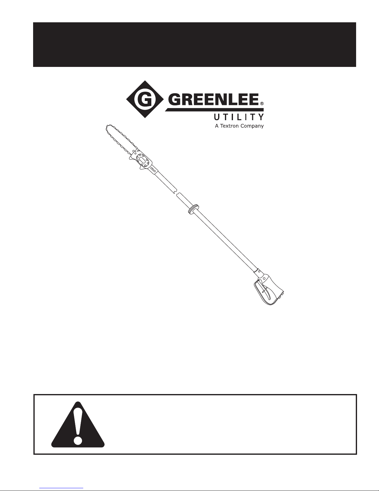
Long-Reach Chain Saws
Serial Codes AMM, AMN, AMP, FRM, FRP, FRR, HAA, HAB, and HAC
Read and understand all of the instructions and
safety information in this manual before operating
or servicing this tool.
99912864 REV 18 © 2016 Greenlee Textron Inc. 4/16
Register this product at www.greenlee.com
Page 2
38568, 43177, and 43178 Long-Reach Chain Saws
Table of Contents
Safety ............................................................................. 2
Purpose of this Manual .................................................. 2
Other Publications .......................................................... 2
Important Safety Information ......................................... 3
Disassembly ................................................................... 4
Inspection ....................................................................... 4
Assembly .................................................................... 5–6
Illustrations and Parts List ........................................ 7–16
Safety
Safety is essential in the use and maintenance of
Greenlee Utility tools and equipment. This service
manual and any markings on the tool provide information for avoiding hazards and unsafe practices related to
the use of this tool. Observe all of the safety information
provided.
Purpose of this Manual
This manual is intended to familiarize all personnel
with the safe service procedures for the following
Greenlee Utility hydraulic tools:
38568 Serial Codes AMM, FRM, and HAB
43177 Serial Codes AMN, FRP, and HAC
43178 Serial Codes AMP, FRR, and HAA
Keep this manual available to all personnel.
Replacement manuals are available upon request at
no charge at www.greenlee.com.
Other Publications
Instruction Manual: Publication 99930749
SAE Standard J1273 (Hose and Hose Assemblies):
Publication 99930323
Greenlee / A Textron Company 4455 Boeing Dr. • Rockford, IL 61109-2988 USA • 815-397-7070
All specications are nominal and may change as design
improvements occur. Greenlee Textron Inc. shall not be liable for
damages resulting from misapplication or misuse of its products.
Loctite and 242 are registered trademarks of Loctite Corporation.
KEEP THIS MANUAL
2
Page 3
38568, 43177, and 43178 Long-Reach Chain Saws
IMPORTANT SAFETY INFORMATION
SAFETY
ALERT
SYMBOL
This symbol is used to call your attention to hazards
or unsafe practices which could result in an injury or
property damage. The signal word, dened below,
indicates the severity of the hazard. The message
after the signal word provides information for
preventing or avoiding the hazard.
Immediate hazards which, if not avoided, WILL result
in severe injury or death.
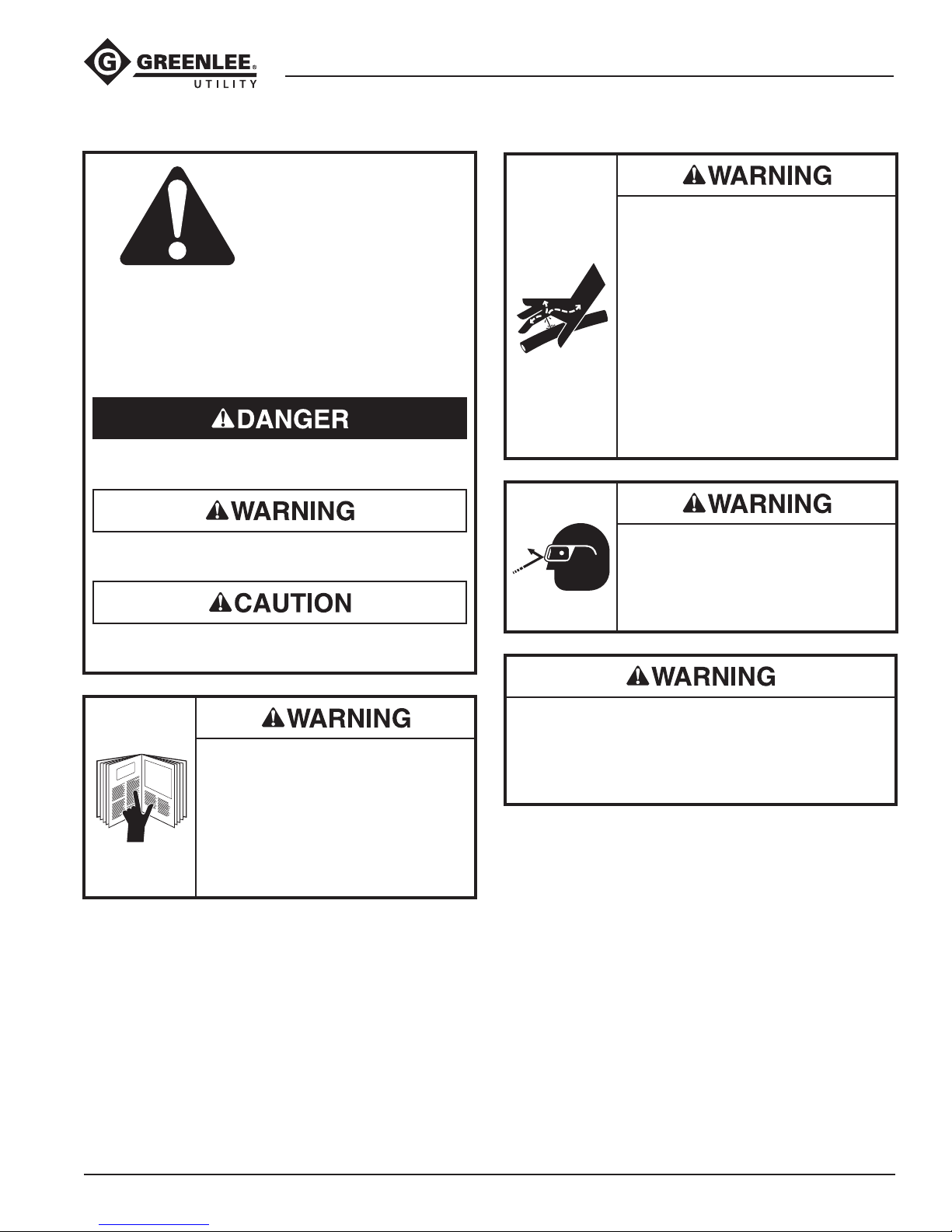
Skin injection hazard:
Oil under pressure easily punctures
skin causing serious injury, gangrene
or death. If you are injured by escaping oil, seek medical attention
immediately.
• Do not use hands to check for
leaks.
• Do not hold hose or couplers
while the hydraulic system is
pressurized.
• Depressurize the hydraulic system
before servicing.
Hazards which, if not avoided, COULD result in
severe injury or death.
Hazards or unsafe practices which, if not avoided,
MAY result in injury or property damage.
Read and understand all of the
instructions and safety information
in this manual before operating or
servicing this tool. Refer also to the
Instruction Manual, which is listed
under “Other Publications.”
Failure to observe this warning could
result in severe injury or death.
Wear eye protection when operating
or servicing this tool.
Failure to wear eye protection could
result in serious eye injury from ying
debris or hydraulic oil.
Do not exceed the maximum hydraulic ow,
pressure relief or back pressure listed in the
Instruction Manual.
Failure to observe this warning could result in severe
injury or death.
Greenlee / A Textron Company 4455 Boeing Dr. • Rockford, IL 61109-2988 USA • 815-397-7070
3
Page 4
Disassembly
38568, 43177, and 43178 Long-Reach Chain Saws
Complete disassembly of the tool is not recommended.
If a complete overhaul is necessary, return the tool to
your nearest authorized Greenlee Utility service center.
The disassembly procedure is divided into sections of
the tool. Disassemble only the section(s) necessary to
complete the repair.
Disassemble the tool on a at, clean surface. Take care
not to lose or damage any parts that may fall free during
disassembly.
Inner and Outer Tubes
1. Remove hex head cap screw (10) and lock washer
(11) which secure outer tube (4). Remove inner
tubes (2 and 3) from ports of handle assembly (8).
Remove handle assembly from outer tube. Plug (5)
may fall free.
2. Remove three oval head machine screws (9) which
secure outer tube to motor assembly (1). Remove
outer tube from motor assembly. Nut carrier (7) may
fall free. Remove inner tubes (2 and 3) from ports of
motor assembly.
3. Remove outer tube (4) from inner tubes (2 and
3). Clean both outer and inner tubes. Inspect
O-rings (22) for signs of cracks or wear. Remove, if
necessary.
Handle Assembly (Serial Codes HAA, HAB, and HAC)
1. Remove two round machine screws (39) from guard
(38). Remove guard from handle (27).
2. Remove retaining ring (46) and trigger pivot (45),
which secures trigger (41).
3. Remove retaining ring (49) to remove spool assembly (35, 36, 28–30) from handle (27).
4. Remove internal retaining ring (30) from spool (35)
to remove Super Spool (28).
Handle Assembly
(Serial Codes AMM, AMN, AMP, FRM, FRP, and FRR)
1. Remove two round head machine screws (39) and
lock washers (40) from guard (38). Remove guard
(38) from handle assembly (27).
2. Remove retaining ring (46) and trigger pivot (45)
which secures trigger (41).
3. Remove internal retaining ring (30) from sleeve (28)
which will allow spring (33) and washer (32) to be
removed.
4. Remove internal retaining ring (50) and washer (37).
5. Remove spool (35) from sleeve (28).
6. Remove external retaining ring (49). Pull sleeve (28)
out of handle (27).
Saw Blade and Chain
1. Remove hex head cap screws (15). Remove cover
(14). Remove saw chain from sprocket (26). Remove
bar (12) from motor assembly (1). Dog and tension
bolt may be removed from saw head if necessary.
2. Remove stop nut (19), sprocket adapter (26), rim
sprocket (18), sprocket key (17), and sprocket
washer (16) from drive shaft.
Motor Assembly
1. Scribe a line across motor cap (55) and saw head
assembly (52) to help align parts correctly during
reassembly. Remove socket head cap screws (66).
Remove motor cap from saw head assembly.
2. Remove idler shaft (58). Remove gear (61) from
idler shaft (58). Remove gear (61) and Woodruff key
(59) from drive shaft (57). Remove gasket (62) from
motor. Remove dowel pins (63), if necessary.
3. Remove retaining ring (65). Drive shaft may be
driven out of saw head assembly, threaded end rst,
using a rubber mallet. Remove ball bearing (64) from
drive shaft.
4. Bearings (53 and 56) should be removed from
saw head assembly and motor cap only if they are
damaged. Bearings are pressed in, and should be
removed only if the necessary equipment to replace
them is available.
5. Remove metering screw (68), which controls oil ow
to automatic chain oiler. Remove O-ring (67).
Inspection
Clean all parts with solvent and dry them thoroughly.
Inspect each component as described in this section.
Replace any component that shows wear or damage.
1. Saw Head Assembly and Motor Cap Assembly:
Inspect mating surfaces, gear cavities, oil passageways, etc. for grooves or nicks. If any component
shows wear or damage, replace the entire assembly
with the bearings already pressed in.
2. Inspect all other disassembled components for
cracks, grooves or nicks.
Greenlee / A Textron Company 4455 Boeing Dr. • Rockford, IL 61109-2988 USA • 815-397-7070
4
Page 5
Assembly
38568, 43177, and 43178 Long-Reach Chain Saws
Refer to the Illustration(s) and Parts List for correct
orientation and placement of parts.
Replace any O-rings, V-rings, seals, and gaskets on
parts that have been disassembled. Apply hydraulic
uid or O-ring lubricant to all O-rings and all metal
surfaces which they must slide over. When installing
an O-ring which must slide over sharp surfaces, use a
rolling motion and be careful not to damage the O-ring.
Wherever the assembly results in metal-to-metal
contact, coat the surfaces with hydraulic uid or O-ring
lubricant.
Motor Assembly
1. If bearings (53 and 56) have been removed from the
motor cap (55) and saw head (52), replace them.
Install O-ring (54) in saw head.
2. Install ball bearing (64) over threaded end of drive
shaft (57). Install non-threaded end of drive shaft
(57) through front of cavity in saw head assembly
(52). Secure with retaining ring (65). Install drive
pin (60) into idler shaft (58) and install idler shaft
into cavity on rear side of saw head assembly (52).
Install Woodruff key (59) into drive shaft (57).
3. Install one gear (61) onto idler shaft (58), aligning
notch in gear over drive pin (60). Install one gear
(61) on drive shaft (57), aligning notch in gear over
Woodruff key (59).
4. Install gasket (62) on saw head assembly (52). Install
dowel pins (63) in saw head assembly.
Install motor cap (55) on saw head assembly,
using the line scribed during disassembly to align
parts correctly. Secure motor cap (55) to saw head
assembly with washers (70) and socket head cap
screws (66). Torque to 9 newton-meters (80 in-lb).
5. If metering screw has been removed, install O-ring
(67) on metering screw (68). Install metering screw,
bottoming it out in the cavity, and backing it off
about 1/2 turn.
Note: Metering screw is not adjusted at this point.
After assembly is completed, adjust automatic oiler
before using the tool.
6. If O-rings (69) have been removed, install a new
O-ring inside each port of saw head assembly (52).
Saw Bar and Chain
1. Install sprocket key (17), sprocket washer (16),
sprocket (18), sprocket adapter (26), and stop nut
(19) on threaded end of drive shaft. Ensure that
sprocket adapter is assembled onto shaft with
1.500 dia. face oriented toward stop nut.
2. Set saw head down at. Install dog (21) with small
diameter side facing out. Install adjusting screw (20)
into back side of saw head and thread into dog.
3. Place bar with chain wrapped around it onto saw
head. Ensure dog is placed in the guide hole around
the outer edge of the bar. Place cover (14) with hex
head cap screws (15) over bar and secure screws
into saw head loosely but enough to hold bar at
onto saw head with dog in guide hole.
4. Place chain around sprocket and bar.
Note: Lubricate the saw chain (13) well (especially a
new chain) before installation. Oil all joints and work
oil into rivet holes. The best way to oil a new chain is
to soak it in oil before installation.
5. Tighten adjusting screw (20) until proper tension is
achieved. (Refer to “Adjusting Chain Tension” in the
“Maintenance” section of the Instruction Manual.)
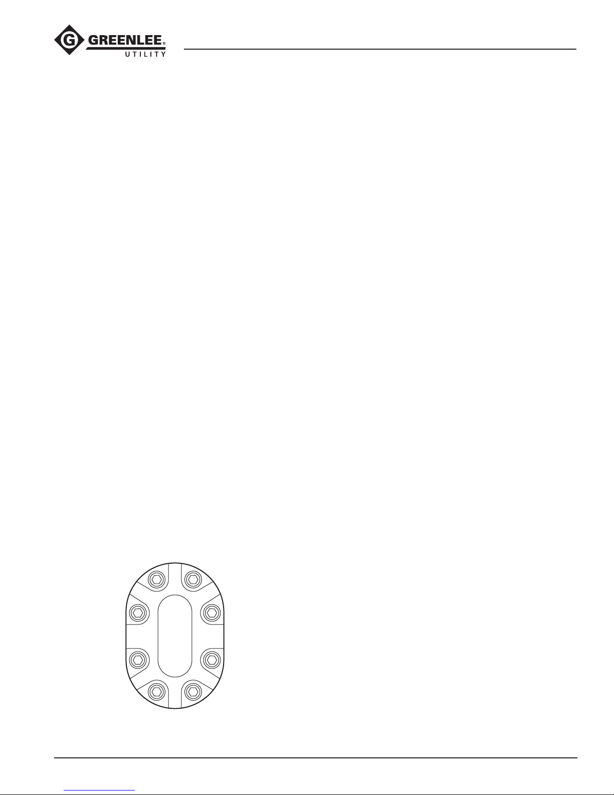
6. Secure hex head cap screws (15) to 16.9 newtonmeters (150 in-lb).
Torque Sequence
5 7
1
3
8 6
Greenlee / A Textron Company 4455 Boeing Dr. • Rockford, IL 61109-2988 USA • 815-397-7070
4
2
5
Page 6
Assembly (cont’d)
38568, 43177, and 43178 Long-Reach Chain Saws
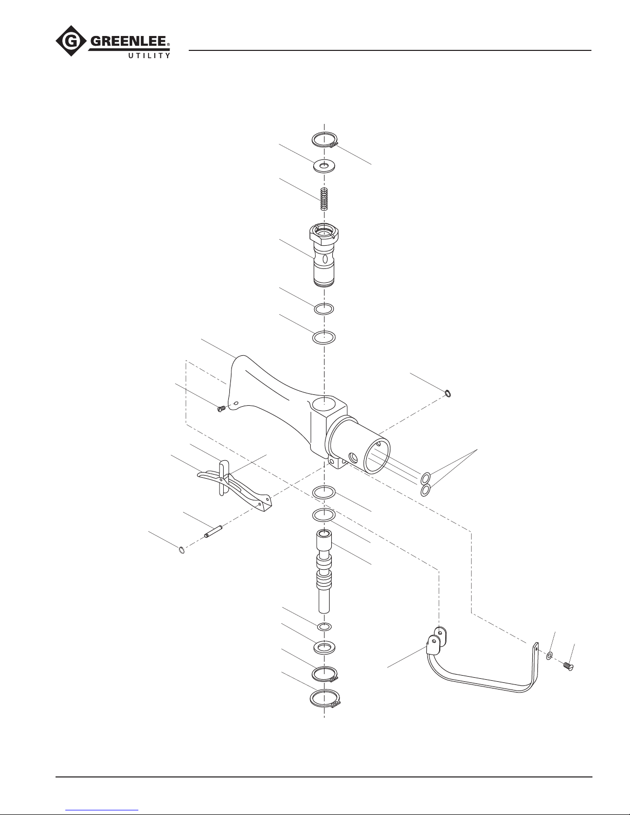
Handle Assembly (Serial Codes HAA, HAB, and HAC)
1. Install O-ring (29) on the Super Spool (28).
2. Install Super Spool (28) into spool (35) and retain
with retaining ring (30).
3. Install O-ring (34) and ring (32) in handle body (27).
4. Install O-ring (36) onto spool (35).
5. Install spool (35), washer (31), and spring (33) into
handle body (27) and retain with retaining ring (49).
6. Position trigger (41) onto handle assembly. Slide
trigger pivot (45) through holes and secure with
retaining rings (46).
7. Position guard (38) onto handle assembly. Secure
with roll pin (51) and round head machine screws
(39).
8. Secure grips (37, 50) to handle using nut and bolt
(40, 48).
9. Position trigger pin (44) through trigger (41), safety
latch (42), and torsion spring (43). Secure with
retaining rings (46).
Handle Assembly
(Serial Codes AMM, AMN, AMP, FRM, FRP, and FRR)
1. Install O-rings (47) in the valve handle (27).
2. Install O-ring (48) in valve handle (27). Install
O-rings (34 and 48) in sleeve (28). Install sleeve (28)
in valve handle (27). Secure with external retaining
ring (49).
3. Install O-ring (36) on spool (35). Install spool (35)
through trigger end of valve handle.
4. Install spring (33), and O-ring (32) and secure with
retaining ring (30).
5. Install washer (37) and secure with retaining ring
(50).
6. Position trigger (41) onto handle assembly. Slide
trigger pivot (45) through holes and secure with
retaining rings (46).
7. Position guard (38) onto handle assembly. Secure
with lock washer (40) and round head machine
screws (39).
Inner and Outer Tubes
1. Hold the two inner tubes (2 and 3) together, and
slide one O-ring (22) over the tubes, halfway down
the length of the tubes. Turn one of the tubes end
for end, so that the O-ring forms a gure 8 around
the tubes. Slide one O-ring (22) in a gure 8 over
each end of the tubes, pushing the O-ring down
approximately 15.9 cm (6-1/4") from the end of the
inner tubes.
Note: Inner tube (2) is the pressure tube, and should
be marked either with marking tape or with dye on
both ends. Be careful to install the marked tube in
P port of both the motor assembly and the valve
assembly. Improper installation of the inner tubes
will cause the saw to run backwards.
2. Lubricate tips of inner tubes with hydraulic oil to
ease assembly. Press inner tube (3) into the top
(return) port of motor assembly (1). Press inner tube
(2) into the lower (pressure) port of motor assembly,
which is marked P.
3. Press one nut carrier (7) into corresponding holes
in end of outer tube (4). Nut carrier may be glued to
outer tube to hold it in place during assembly. Slide
the outer tube over the inner tubes, with the end
of the outer tube which has small holes for securing to the handle assembly (8) away from the motor
assembly (1). Place the outer tube into the motor
assembly, aligning the nut carrier under the holes
in the motor assembly. Apply one drop of threadlocking compound (Loctite 242 or equivalent) to
three oval head machine screws (9). Install screws,
securing outer tube to motor assembly.
4. For proper tool operation, the same inner tube (2)
that was installed in the pressure port of the motor
assembly (1) must be installed in the pressure port
of the handle assembly (8). Lubricate tips of inner
tubes with hydraulic oil to ease assembly. Press
inner tube (3) into the top (return) port of handle
assembly (8). Press inner tube (2) into the lower
(pressure) port, which is marked P.
5. Insert plug (5) and O-ring (6) in outer tube (4) and
install in valve handle (8). Secure with cap screw
(10) and washer (11).
Greenlee / A Textron Company 4455 Boeing Dr. • Rockford, IL 61109-2988 USA • 815-397-7070
6
Page 7
38568, 43177, and 43178 Long-Reach Chain Saws
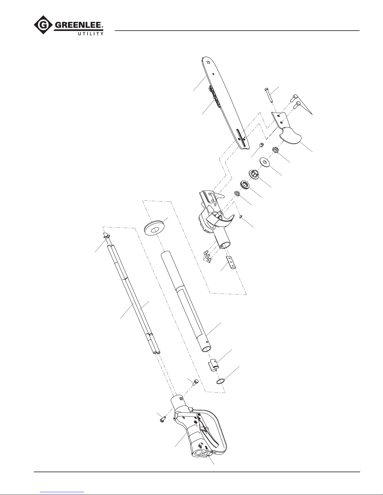
Illustration—Main for Serial Codes HAA, HAB, and HAC
12
20
22
23
13
15
21
19
24
26
18
16
17
9
7
14
2
3
Note: O-rings (22) must be twisted into
a figure 8 configuration and slid over
inner tubes (2 and 3) as shown.
10
10
8
Greenlee / A Textron Company 4455 Boeing Dr. • Rockford, IL 61109-2988 USA • 815-397-7070
7
4
5
6
P
Page 8
38568, 43177, and 43178 Long-Reach Chain Saws
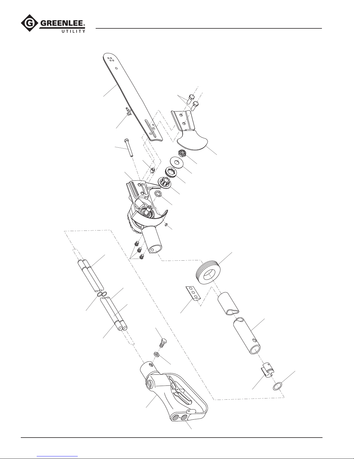
Note: O-rings (22) must be twisted into
Illustration—Main for Serial Codes AMM, AMN, and AMP
12
22
20
13
15
21
19
1
24
18
26
16
17
9
14
23
22
22
a figure 8 configuration and slid over
inner tubes (2 and 3) as shown.
Greenlee / A Textron Company 4455 Boeing Dr. • Rockford, IL 61109-2988 USA • 815-397-7070
2
3
7
10
11
8
P
4
6
5
8
Page 9
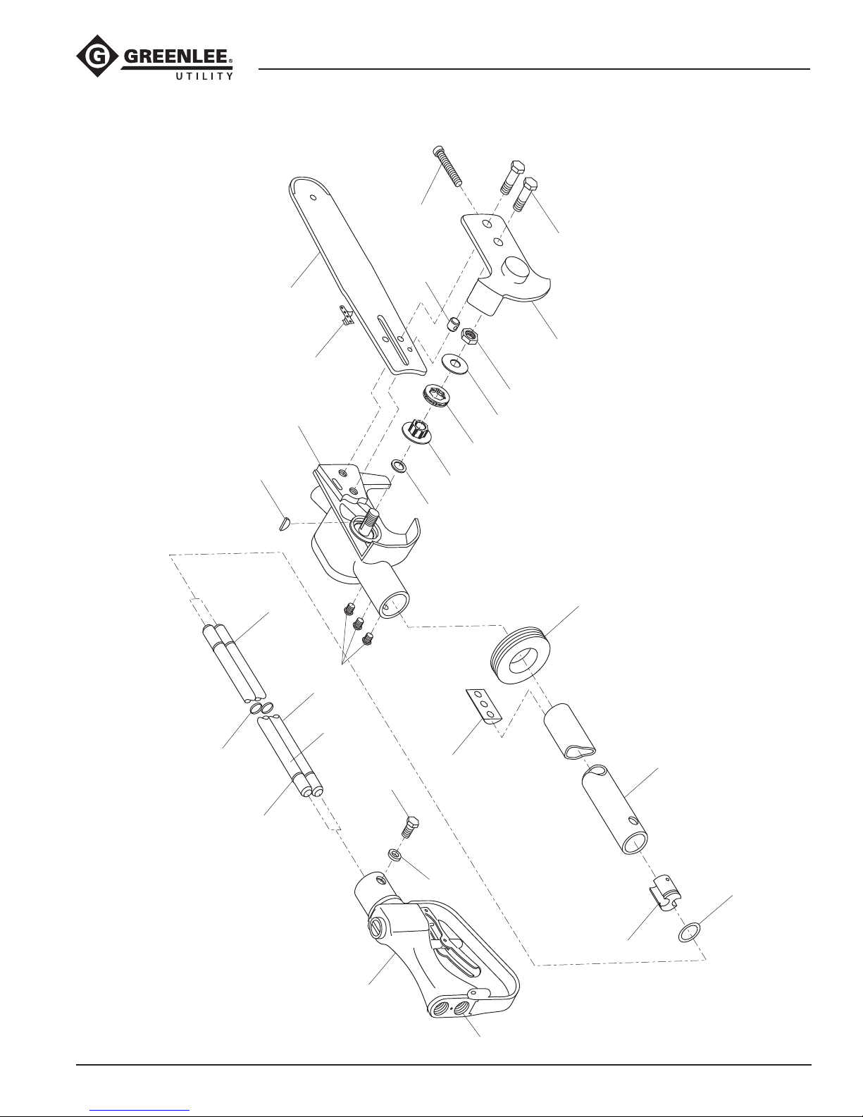
38568, 43177, and 43178 Long-Reach Chain Saws
Illustration—Main for Serial Codes FRM, FRP, and FRR
20
15
21
12
22
17
22
13
19
1
26
16
9
2
3
7
24
18
14
23
4
22
Note: O-rings (22) must be twisted into
a figure 8 configuration and slid over
inner tubes (2 and 3) as shown.
Greenlee / A Textron Company 4455 Boeing Dr. • Rockford, IL 61109-2988 USA • 815-397-7070
10
11
5
8
P
6
9
Page 10
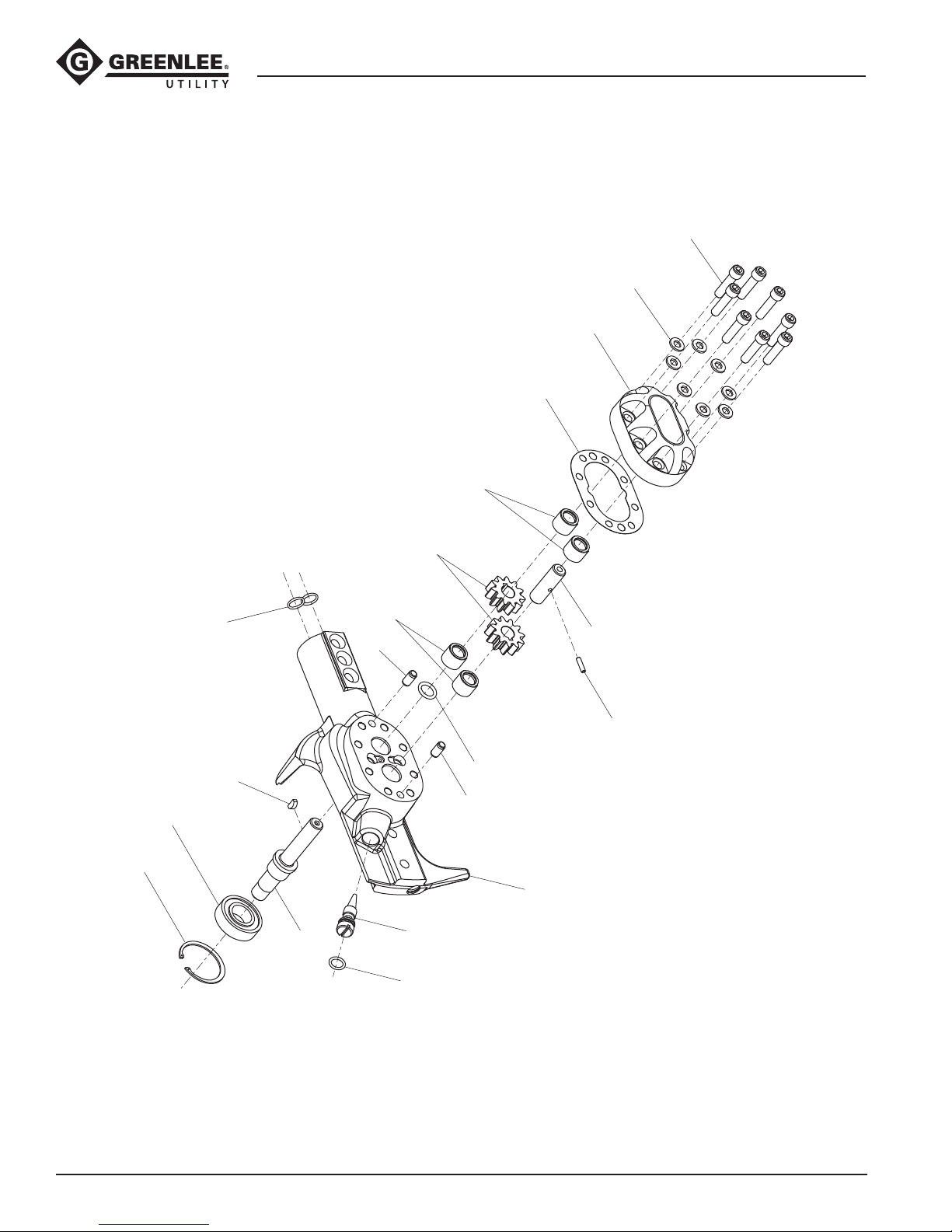
38568, 43177, and 43178 Long-Reach Chain Saws
Illustration—Motor Assembly for Serial Codes
AMM, AMN, AMP, HAA, HAB, and HAC
56
66
70
55
62
65
64
69
59
T
P
63
57
61
53
58
60
54
63
52
68
67
Greenlee / A Textron Company 4455 Boeing Dr. • Rockford, IL 61109-2988 USA • 815-397-7070
10
Page 11
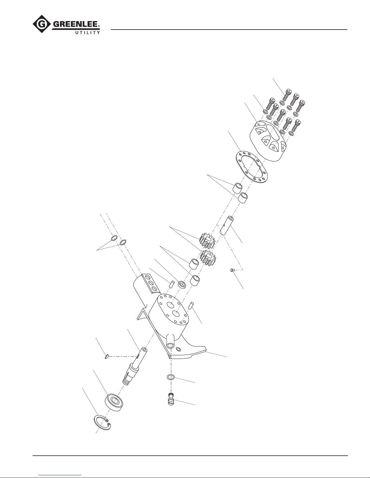
38568, 43177, and 43178 Long-Reach Chain Saws
Illustration—Motor Assembly for Serial Codes FRM, FRP, and FRR
66
70
55
62
56
65
64
69
59
T
P
61
57
53
54
63
63
67
58
60
52
Greenlee / A Textron Company 4455 Boeing Dr. • Rockford, IL 61109-2988 USA • 815-397-7070
68
11
Page 12
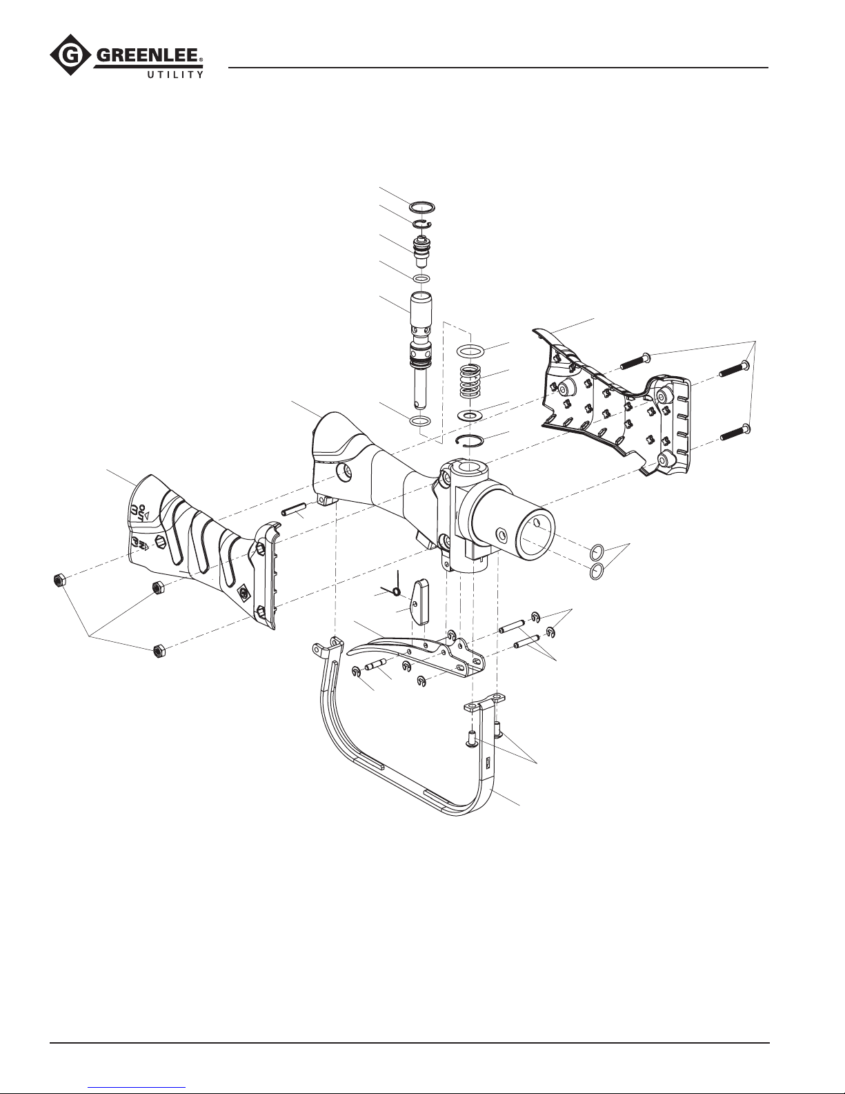
38568, 43177, and 43178 Long-Reach Chain Saws
Illustration—Handle Assembly for Serial Codes HAA, HAB, and HAC
32
30
28
29
35
50
34
33
48
40
37
27
51
41
43
36
46
42
31
49
47
46
45
44
39
Greenlee / A Textron Company 4455 Boeing Dr. • Rockford, IL 61109-2988 USA • 815-397-7070
38
12
Page 13
38568, 43177, and 43178 Long-Reach Chain Saws
Illustration—Handle Assembly for Serial Codes
AMM, AMN, AMP, FRM, FRP, and FRR
32
41
51
42
27
33
28
34
29
43, 44, 46
30
46
47
45
46
Greenlee / A Textron Company 4455 Boeing Dr. • Rockford, IL 61109-2988 USA • 815-397-7070
36
37
50
49
31
48
35
40
39
38
13
Page 14
38568, 43177, and 43178 Long-Reach Chain Saws
Parts List for Serial Codes HAA, HAB, and HAC
UPC No.
Key 78-3310- Part No. Description Qty
1 43558 50435582 Motor assembly (includes items 52–69) .............1
2 42491 50424911 Pressure tube (model 38568) .............................1
43386 50433865 Pressure tube (model 43177) ............................. 1
43385 50433857 Pressure tube (model 43178) ............................. 1
3 42492 50424920 Return tube (model 38568) ................................1
43388 50433881 Return tube (model (43177) ...............................1
43387 50433873 Return tube (model 43178) ................................1
4 43389 50433890 Outer tube (model 38568) ..................................1
48262 50482629 Outer tube (model 43177) .................................. 1
48263 50482637 Outer tube (model 43178) .................................. 1
5 41121 50411214 Plug ...................................................................1
6* O-ring, .937 x 1.062 x .062–90 ..........................1
7 40118 50401184 Carrier, nut .........................................................1
8 48818 50488180 Handle assembly (includes items 27–51) ...........1
9 Screw, machine, 1/4–20 x .500 oval head ..........3
10 Screw, cap, 1/4–20 x .750 hex head, grade 5 ....2
11 Lock washer, 1/4" ..............................................2
12 43369 50433695 Saw bar ............................................................. 1
13 43370 50433709 Saw chain, .325" pitch ....................................... 1
14 02093 52047938 Cover ................................................................. 1
15 Screw, cap, 5/16–18 x 1.00 hex head ................ 2
16 t Spacer ...............................................................1
17 t Woodruff key, #2 ................................................1
18 55101 90551010 Rim sprocket, .325" pitch ..................................1
19 t Nut, hex, 1/2–20 ................................................1
20 Screw, machine, 1/4–20 x 2.00 fillister head ......1
21 02094 52054770 Dog .................................................................... 1
22* O-ring, .875 x 1.00 x .062–70 ............................ 2
23 42015 50420154 Rubber grommet ................................................ 1
24 t Washer, flat, .530 x 1.50 x .050 ..........................1
26 t Adapter, sprocket ...............................................1
27 03542 52065777 Handle ............................................................... 1
28 00917 52063610 Super Spool ....................................................... 1
29* O-ring, .375 x .500 ............................................. 1
30 48540 50485407 Retaining ring .................................................... 1
31 48310 50483102 Washer, .76 x .734 .............................................1
32* Ring ..................................................................1
33 00399 52060673 Trigger spring .....................................................1
34* O-ring, .612 x .818 ............................................. 1
35 00380 52060643 Spool ................................................................. 2
36* O-ring, 1/2 x 5/8 ...............................................1
37 Right handle grip ................................................1
38 Trigger guard .....................................................2
39 Screw, #10-32 x .375 button head .....................2
40 Lock nut, 8-32 ...................................................3
41 Trigger ...............................................................1
UPC No.
Key 78-3310- Part No. Description Qty
42 Safety latch ........................................................1
43 Torsion spring ....................................................1
44 Pin ..................................................................... 1
45 Trigger pivot .......................................................2
46 Retaining ring ....................................................6
47* O-ring, urethane ................................................. 4
48 Screw, 8-32 x 1.00 button cap ...........................3
49 41648 50416480 Internal retaining ring, .750 x .035 .....................1
50 Left handle grip ..................................................1
51 Roll pin ..............................................................1
52 02089 52058055 Saw head assembly
(includes items 53, 54, 69) .................................1
53 41591 50415911 Needle bearing, .439 x .625 x .500 ....................2
54* O-ring, .500 x .687 x .093–80 ............................ 1
55 40405 50404053 Motor cap assembly with bearings
(includes items 56, 66, 70) .................................1
56 41591 50415911 Needle bearing, .439 x .625 x .500 ....................2
57 43839 50438395 Shaft .................................................................. 1
58 40114 50401144 Idler shaft...........................................................1
59 40115 50401154 Woodruff key ......................................................1
60 41593 50415930 Pin, drive, .123 x .209 square head ....................1
61 41594 50415940 Gear, 11-tooth ....................................................2
62* Gasket, 2.09 x 3.09 x .0015 ............................... 1
63 41596 50415960 Pin, dowel, .250 x .500 ......................................2
64 41598 50415981 Ball bearing ........................................................ 1
65 41482 50414821 Retaining ring, 1.375" ........................................ 1
66 Screw, cap, 1/4–20 x 1.000 socket head ...........8
67* O-ring, .375 x .500 x .062–70 ............................ 1
68 02092 52047936 Screw, metering .................................................1
69* O-ring, .437 x .562 x .062–90 ............................ 2
70 Washer, 6 mm, hard ...........................................8
Kits
* 03550 52071999 Packing kit (includes items
marked with an asterisk)
02088 52058054 Motor assembly (includes items 14, 15,
20, 21, 52–70)
48818 50488180 Handle assembly (includes items 27–51)
02089 52058055 Saw head assembly
(includes items 53, 54, 69)
40405 50404053 Motor cap assembly
(includes items 56, 66, 70)
06707 52071998 Safety trigger assembly (includes items 41-46)
t 12657 52028588 Drive repair kit (includes items marked with t)
00376 52060640 Trigger guard kit (includes items 38, 39, 51)
06613 52079544 Grip kit (includes items 37, 40, 48, 50)
Decals
46293 50462938 Decal .................................................................1
41547 50415471 Decal, Greenlee Utility ........................................1
Greenlee / A Textron Company 4455 Boeing Dr. • Rockford, IL 61109-2988 USA • 815-397-7070
14
Page 15
38568, 43177, and 43178 Long-Reach Chain Saws
Parts List for Serial Codes AMM, AMN, and AMP
UPC No.
Key 78-3310- Part No. Description Qty
1 43558 50435582 Motor assembly (includes items 52–69) .............1
2 42491 50424911 Pressure tube (model 38568) .............................1
43386 50433865 Pressure tube (model 43177) ............................. 1
43385 50433857 Pressure tube (model 43178) ............................. 1
3 42492 50424920 Return tube (model 38568) ................................1
43388 50433881 Return tube (model (43177) ...............................1
43387 50433873 Return tube (model 43178) ................................1
4 43389 50433890 Outer tube (model 38568) ..................................1
48262 50482629 Outer tube (model 43177) .................................. 1
48263 50482637 Outer tube (model 43178) .................................. 1
5 41121 50411214 Plug ...................................................................1
6* O-ring, .937 x 1.062 x .062–90 ..........................1
7 40118 50401184 Carrier, nut .........................................................1
8 48818 50488180 Handle assembly (includes items 27–51) ...........1
9 Screw, machine, 1/4–20 x .500 oval head ..........3
10 Screw, cap, 1/4–20 x .750 hex head, grade 5 ....2
11 Lock washer, 1/4" ..............................................2
12 43369 50433695 Saw bar ............................................................. 1
13 43370 50433709 Saw chain, .325" pitch ....................................... 1
14 02093 52047938 Cover ................................................................. 1
15 Screw, cap, 5/16–18 x 1.00 hex head ................ 2
16 t Spacer ...............................................................1
17 t Woodruff key, #2 ................................................1
18 55101 90551010 Rim sprocket, .325" pitch ..................................1
19 t Nut, hex, 1/2–20 ................................................1
20 Screw, machine, 1/4–20 x 2.00 fillister head ......1
21 02094 52054770 Dog .................................................................... 1
22* O-ring, .875 x 1.00 x .062–70 ............................ 2
23 42015 50420154 Rubber grommet ................................................ 1
24 t Washer, flat, .530 x 1.50 x .050 ..........................1
26 t Adapter, sprocket ...............................................1
27 48815 50488155 Handle ............................................................... 1
28 43420 50434209 Sleeve ................................................................ 1
29* O-ring, .750 x .875 x .062–90 ............................ 1
30 41712 50417122 Retaining ring, .750" .......................................... 1
31* O-ring, .787 x .889 x .051–70 ............................ 1
32 41095 50410952 Cap ....................................................................1
33 42865 50428651 Spring ................................................................ 1
34* O-ring, .437 x .625 x .093–90 ............................ 1
35 43421 50434217 Spool ................................................................. 1
36* O-ring, .312 x .437 x .062–70 ............................ 1
37 41096 50410962 Washer, .355 x .615 x .030 ................................1
38 48817 50488171 Trigger guard .....................................................1
39 Screw, machine, #10-32 x .375 round head .......1
40 Lock washer, #10 ...............................................1
41 04797 50047973 Trigger ...............................................................1
UPC No.
Key 78-3310- Part No. Description Qty
42 04798 50047981 Latch, trigger interlock ....................................... 1
43 04799 50047990 Spring, torsion .................................................... 1
44 04800 50048007 Pin ..................................................................... 1
45 42547 50425471 Trigger pivot .......................................................1
46 42827 50428270 Retaining ring .................................................... 4
47* O-ring, .437 x .562 x .062–90 ............................ 2
48* O-ring, .875 x 1.00 x .062–70 ............................ 1
49 54819 90548191 Retaining ring, .875" .......................................... 1
50 41297 50412971 Retaining ring, .625" .......................................... 1
51 Screw, cap, #10-32 x .375
button socket head ............................................2
52 02089 52058055 Saw head assembly
(includes items 53, 54, 69) .................................1
53 41591 50415911 Needle bearing, .439 x .625 x .500 ....................2
54* O-ring, .500 x .687 x .093–80 ............................ 1
55 40405 50404053 Motor cap assembly with bearings
(includes items 56, 66, 70) .................................1
56 41591 50415911 Needle bearing, .439 x .625 x .500 ....................2
57 43839 50438395 Shaft .................................................................. 1
58 40114 50401144 Idler shaft...........................................................1
59 40115 50401154 Woodruff key ......................................................1
60 41593 50415930 Pin, drive, .123 x .209 square head ....................1
61 41594 50415940 Gear, 11-tooth ....................................................2
62* Gasket, 2.09 x 3.09 x .0015 ............................... 1
63 41596 50415960 Pin, dowel, .250 x .500 ......................................2
64 41598 50415981 Ball bearing ........................................................ 1
65 41482 50414821 Retaining ring, 1.375" ........................................ 1
66 Screw, cap, 1/4–20 x 1.000 socket head ...........8
67* O-ring, .375 x .500 x .062–70 ............................ 1
68 02092 52047936 Screw, metering .................................................1
69* O-ring, .437 x .562 x .062–90 ............................ 2
70 Washer, 6 mm, hard ...........................................8
Kits
* 48254 50482548 Packing kit (includes items
marked with an asterisk)
02088 52058054 Motor assembly (includes items 14, 15,
20, 21, 52–70)
48818 50488180 Handle assembly (retrofits to Cool Grip handle)
(includes items 27–51)
02089 52058055 Saw head assembly
(includes items 53, 54, 69)
40405 50404053 Motor cap assembly
(includes items 56, 66, 70)
04796 50047965 Safety trigger assembly (includes items 41-46)
t 12657 52028588 Drive repair kit (includes items marked with t)
Decals
46293 50462938 Decal .................................................................1
41547 50415471 Decal, Greenlee Utility ........................................1
Greenlee / A Textron Company 4455 Boeing Dr. • Rockford, IL 61109-2988 USA • 815-397-7070
15
Page 16
38568, 43177, and 43178 Long-Reach Chain Saws
Parts List for Serial Codes FRM, FRP, and FRR
UPC No.
Key 78-3310- Part No. Description Qty
1 43558 50435582 Motor assembly (includes items 52–69) .............1
2 42491 50424911 Pressure tube (model 38568) .............................1
43386 50433865 Pressure tube (model 43177) ............................. 1
43385 50433857 Pressure tube (model 43178) ............................. 1
3 42492 50424920 Return tube (model 38568) ................................1
43388 50433881 Return tube (model (43177) ...............................1
43387 50433873 Return tube (model 43178) ................................1
4 43389 50433890 Outer tube (model 38568) ..................................1
48262 50482629 Outer tube (model 43177) .................................. 1
48263 50482637 Outer tube (model 43178) .................................. 1
5 41121 50411214 Plug ...................................................................1
6* O-ring, .937 x 1.062 x .062–90 ..........................1
7 40118 50401184 Carrier, nut .........................................................1
8 48818 50488180 Handle assembly (includes items 27–51) ...........1
9 Screw, machine, 1/4–20 x .500 oval head ..........3
10 Screw, cap, 1/4–20 x .750 hex head, grade 5 ....2
11 Lock washer, 1/4" ..............................................2
12 43369 50433695 Saw bar ............................................................. 1
13 43370 50433709 Saw chain, .325" pitch ....................................... 1
14† 40846 50408461 Cover ................................................................. 1
15† Screw, cap, 5/16–18 x 1.500 hex head ..............2
16 t Spacer ...............................................................1
17 t Woodruff key, #2 ................................................1
18 55101 90551010 Rim sprocket, .325" pitch ..................................1
19 t Nut, hex, 1/2–20 ................................................1
20† Screw, machine, 1/4–20 x 2.00 fillister head ......1
21† 40197 50401972 Dog .................................................................... 1
22* O-ring, .875 x 1.00 x .062–70 ............................ 2
23 42015 50420154 Rubber grommet ................................................ 1
24 t Washer, flat, .530 x 1.50 x .050 ..........................1
26 t Adapter, sprocket ...............................................1
27 48815 50488155 Handle ............................................................... 1
28 43420 50434209 Sleeve ................................................................ 1
29* O-ring, .750 x .875 x .062–90 ............................ 1
30 41712 50417122 Retaining ring, .750" .......................................... 1
31* O-ring, .787 x .889 x .051–70 ............................ 1
32 41095 50410952 Cap ....................................................................1
33 42865 50428651 Spring ................................................................ 1
34* O-ring, .437 x .625 x .093–90 ............................ 1
35 43421 50434217 Spool ................................................................. 1
36* O-ring, .312 x .437 x .062–70 ............................ 1
37 41096 50410962 Washer, .355 x .615 x .030 ................................1
38 48817 50488171 Trigger guard .....................................................1
39 Screw, machine, #10-32 x .375 round head .......1
40 Lock washer, #10 ...............................................1
41 04797 50047973 Trigger ...............................................................1
42 04798 50047981 Latch, trigger interlock ....................................... 1
UPC No.
Key 78-3310- Part No. Description Qty
43 04799 50047990 Spring, torsion .................................................... 1
44 04800 50048007 Pin ..................................................................... 1
45 42547 50425471 Trigger pivot .......................................................1
46 42827 50428270 Retaining ring .................................................... 4
47* O-ring, .437 x .562 x .062–90 ............................ 2
48* O-ring, .875 x 1.00 x .062–70 ............................ 1
49 54819 90548191 Retaining ring, .875" .......................................... 1
50 41297 50412971 Retaining ring, .625" .......................................... 1
51 Screw, cap, #10-32 x .375
button socket head ............................................2
52† 40595 50405950 Saw head assembly
(includes items 53, 54, 69) .................................1
53 41591 50415911 Needle bearing, .439 x .625 x .500 ....................2
54* O-ring, .500 x .687 x .093–80 ............................ 1
55 40405 50404053 Motor cap assembly with bearings
(includes items 56, 66, 70) .................................1
56 41591 50415911 Needle bearing, .439 x .625 x .500 ....................2
57 43839 50438395 Shaft .................................................................. 1
58 40114 50401144 Idler shaft...........................................................1
59 40115 50401154 Woodruff key ......................................................1
60 41593 50415930 Pin, drive, .123 x .209 square head ....................1
61 41594 50415940 Gear, 11-tooth ....................................................2
62* Gasket, 2.09 x 3.09 x .0015 ............................... 1
63 41596 50415960 Pin, dowel, .250 x .500 ......................................2
64 41598 50415981 Ball bearing ........................................................ 1
65 41482 50414821 Retaining ring, 1.375" ........................................ 1
66 Screw, cap, 1/4–20 x 1.000 socket head ...........8
67*† O-ring, .375 x .500 x .062–70 ............................ 1
68† 40189 50401891 Screw, metering, 1/8 NPTF .................................1
69* O-ring, .437 x .562 x .062–90 ............................ 2
70 Washer, 6 mm, hard ...........................................8
Kits
* 48254 50482548 Packing kit (includes items
marked with an asterisk)
48818 50488180 Handle assembly (retrofits to Cool Grip handle)
(includes items 27–51)
40595 50405950 Saw head assembly
(includes items 53, 54, 69)
40405 50404053 Motor cap assembly
(includes items 56, 66, 70)
04796 50047965 Safety trigger assembly (includes items 41-46)
t 12657 52028588 Drive repair kit (includes items marked with t)
† 02090 52058056 Retrofit kit (replaces items marked with †);
converts to AMM/AMN/AMP model
Note: Motor assembly for serial codes
AMM/AMN/AMP is interchangeable as retrofit kit.
Decals
46293 50462938 Decal .................................................................1
41547 50415471 Decal, Greenlee Utility ........................................1
4455 Boeing Drive • Rockford, IL 61109-2988 • USA • 815-397-7070
An ISO 9001 Company • Greenlee Textron Inc. is a subsidiary of Textron Inc.
www.greenlee.com
USA Tel: 800-435-0786
Fax: 800-451-2632
Canada Tel: 800-435-0786
Fax: 800-524-2853
International Tel: +1-815-397-7070
Fax: +1-815-397-9247
 Loading...