

Page 1
INSTRUCTION MANUAL
03561
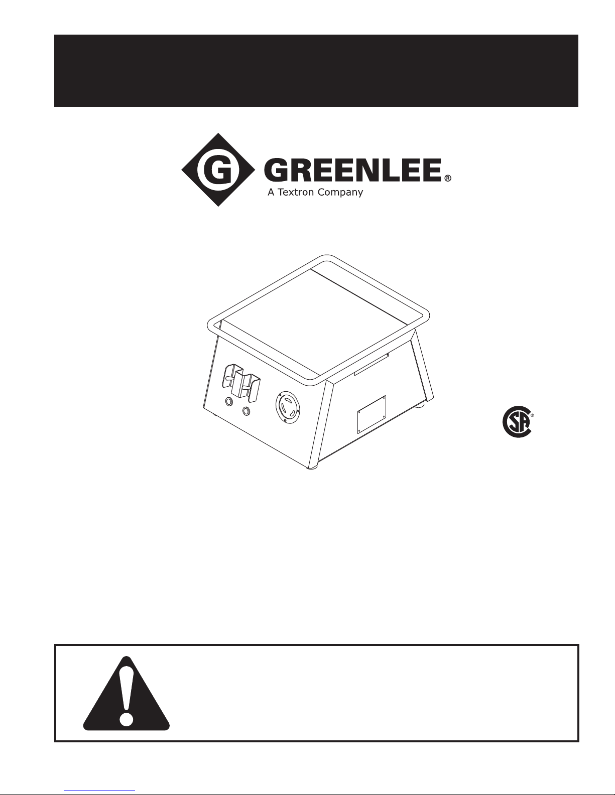
Speed Booster
for the Ultra Tugger
Read and understand all of the instructions and
safety information in this manual before operating
or servicing this tool.
®
NRTL/C
LR 91904-8
99923394 © 2008 Greenlee Textron Inc. IM 1316 REV 7 2/08
Page 2
03561 Speed Booster
Safety Information
Electrical Shock Hazard:
The Speed Booster is for use with
the Greenlee Ultra Tugger Cable
Puller only. The Speed Booster produces more than 120 volts; plugging
anything other than the Ultra Tugger
into the Speed Booster could result
in serious injury or death.
Read and understand the
instructions supplied with the Ultra
Tugger. Failure to observe this
warning could result in an accident
resulting in severe injury or death.
\
Description
The Speed Booster increases the voltage supplied to
the Ultra Tugger® motor. The Speed Booster will allow
the Ultra Tugger to pull cable approximately twice as
fast as normal when the pulling force is less than 2500
pounds. The Speed Booster shuts off automatically and
the Ultra Tugger resumes normal pulling speed when the
pulling force exceeds 2500 pounds.
In order to use the Ultra Tugger with the Speed Booster,
the plug on the end of the Ultra Tugger power cord must
be changed to t the receptacle of the Speed Booster.
An adapter cord is included with the Speed Booster so
that the Ultra Tugger can still be used without the Speed
Booster.
Greenlee / A Textron Company 4455 Boeing Dr. • Rockford, IL 61109-2988 USA • 815-397-7070
All specications are nominal and may change as design
improvements occur. Greenlee Textron Inc. shall not be liable for
damages resulting from misapplication or misuse of its products.
KEEP THIS MANUAL
2
Page 3
03561 Speed Booster
1
2
3
5
4
HIGH SPEEDLOW SPEED
Electric Shock Hazard:
The Speed Booster is for use with the Greenlee Ultra Tugger™ Cable Puller only. The Speed Booster
produces more than 120 volts; plugging anything other than the Ultra Tugger™ into the Speed Booster
can result in severe injury or death.
DECAL NO. 500 3580.0 REV 1
03561 SPEED BOOSTER
for the Ultra Tugger
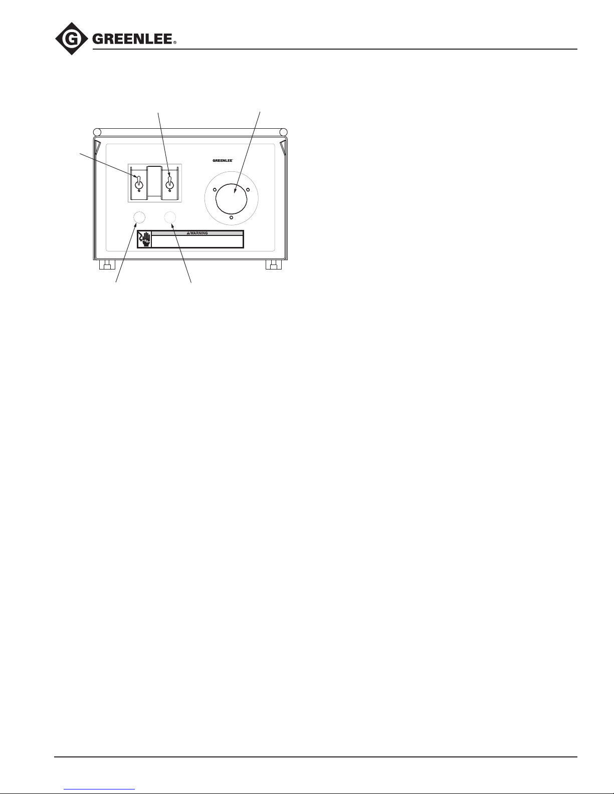
Front Panel Identification
The ESCXX Cable Cutter is a hand-held tool intended to
cut copper and aluminum cable up to 85 mm (3-1/4").
1. Low Speed toggle switch: Used to reset Speed
Booster to low speed mode.
2. High Speed toggle switch: Used to turn Speed
Booster to high speed mode.
3. Receptacle for Ultra Tugger only!
4. Amber Light: Indicates that main power is on, and
normal voltage is applied to receptacle (low speed).
5. Red Light: Indicates that the Speed Booster is
working and high voltage is applied to receptacle
(high speed).
Specifications
Height .....................................................9.5 in. (24.1 cm)
Width .......................................................13 in. (33.0 cm)
Depth ....................................................15.5 in. (39.4 cm)
Weight ..................................................... 46 lb. (20.9 kg)
Power Input ........................ 115 VAC; 15 A; 1ø; 50/60 Hz
(125 VAC max.; 80 VAC min.)
Power Output ........... 115/230 VAC; 15/6 A; 1ø; 50/60 Hz
For use only with
Greenlee Ultra Tugger
Operating Temperature Range ......................– 5 to 120°F
(– 20 to 49°C)
Operating Humidity Range .................................. 0 - 98%
Protection .......................................... 20A Circuit Breaker
Thermally protected transformer
with Class B insulation
Greenlee / A Textron Company 4455 Boeing Dr. • Rockford, IL 61109-2988 USA • 815-397-7070
3
Page 4

03561 Speed Booster
Setup
1. Use the instructions provided with the Ultra Tugger
to set up the puller.
2. Plug the Speed Booster into a 120 volt, 20 amp
receptacle.
3. Plug the puller into the receptacle on the Speed
Booster.
Operation
1. Turn on the Speed Booster using the circuit breaker/
power switch located in back of Speed Booster.
Note: The amber indicator will illuminate to indicate that
the power is ON.
2. Turn the puller on. Tail the rope as described in the
instruction manual supplied with the Ultra Tugger.
Note: Allow the puller to run at least 5 seconds before
engaging Speed Booster.
3. Press the toggle switch on the right to switch on
the high speed mode of the Speed Booster. The red
indicator will illuminate.
Note: It may be necessary to hold the switch momentarily.
4. Continue to tail the rope and monitor the force
gauge as usual.
Note: If the pulling force exceeds 2500 pounds, the
Speed Booster will switch off automatically. If the
pulling force drops to less than 2500 pounds, the Speed
Booster will not switch back on automatically; it must be
switched back on manually.
Note: If it becomes necessary to slow down the puller,
press the toggle switch on the left (“Low Speed”) to shut
off the Speed Booster.
Note: If the Speed Booster is used for extended time
in the High Speed mode, the unit may heat up and
automatically activate the thermal shutdown. When this
happens, the Speed Booster will run the puller at normal
speed, but will not boost until it has had time to cool
down.
5. Finish the pull as described in the Ultra Tugger
instruction manual.
6. Turn off the Speed Booster using the power switch
located at the rear. Unplug the Ultra Tugger from the
Speed Booster, and unplug the Speed Booster.
Greenlee / A Textron Company 4455 Boeing Dr. • Rockford, IL 61109-2988 USA • 815-397-7070
4
Page 5
03561 Speed Booster
Ultra Tugger Plug Modification
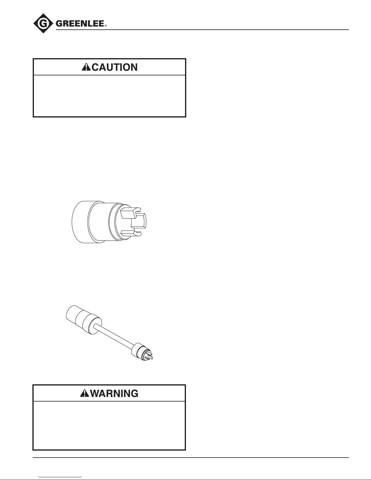
Modication of the plug should only be done by
a Greenlee Authorized Service Center or qualied
electrician.
Failure to observe this precaution may result in
damage to Speed Booster or puller.
To modify the Ultra Tugger for use with the
Speed Booster:
1. Cut off the power plug to the Ultra Tugger.
2.
Connect the Speed Booster Adapter Plug (91868637)
as follows:
• W (Green) Green Wire Ground
• X (Silver) White Wire Neutral
• Y (Brass) Black Wire Line (Hot)
Maintenance
Use of the Speed Booster accelerates brush wear in
the motor of the Ultra Tugger. As the brushes wear,
graphite dust will begin to accumulate on the commutator. This buildup of graphite dust will cause electrical arcing and a noticeable popping noise when the
Speed Booster is used in high-speed mode. When this
happens, service the Ultra Tugger as follows:
1. Refer to the instruction manual supplied with the
Ultra Tugger. Disassemble the Control Box, End
Cover and Commutator.
2. Use compressed air to clean the parts. Wipe down
with a clean, dry lint-free rag.
3. Replace the worn brushes with new brushes
(91867053).
4. Reassemble.
Speed Booster Adapter Plug 91868637
Once the Ultra Tugger power plug has been changed,
use the Ultra Tugger Adapter Cord/Plug Converter
(50042874) to use the Ultra Tugger with 115 VAC 20
Amp line service.
Ultra Tugger Adapter Cord/Plug Converter 50042874
Do not use modied Ultra Tugger directly on 230 VAC
power. Modied Ultra Tugger should be used with
03561 Speed Booster or 50042874 Adapter Cable
only.
Failure to observe this warning could cause tool
malfunction, resulting in severe injury or death.
Greenlee / A Textron Company 4455 Boeing Dr. • Rockford, IL 61109-2988 USA • 815-397-7070
5
Page 6
30
29
28
part
of 23
27
24,25,26
22
21
23
20B
20
20A
1
2
3
4
10
11
5
6
7
10
8
9
7
18
17
16
19
14
15
13
12
20A
20C
20D
20F
20E
17
16
17
16
9
8
Operation
03561 Speed Booster
Greenlee / A Textron Company 4455 Boeing Dr. • Rockford, IL 61109-2988 USA • 815-397-7070
6
Page 7

03561 Speed Booster
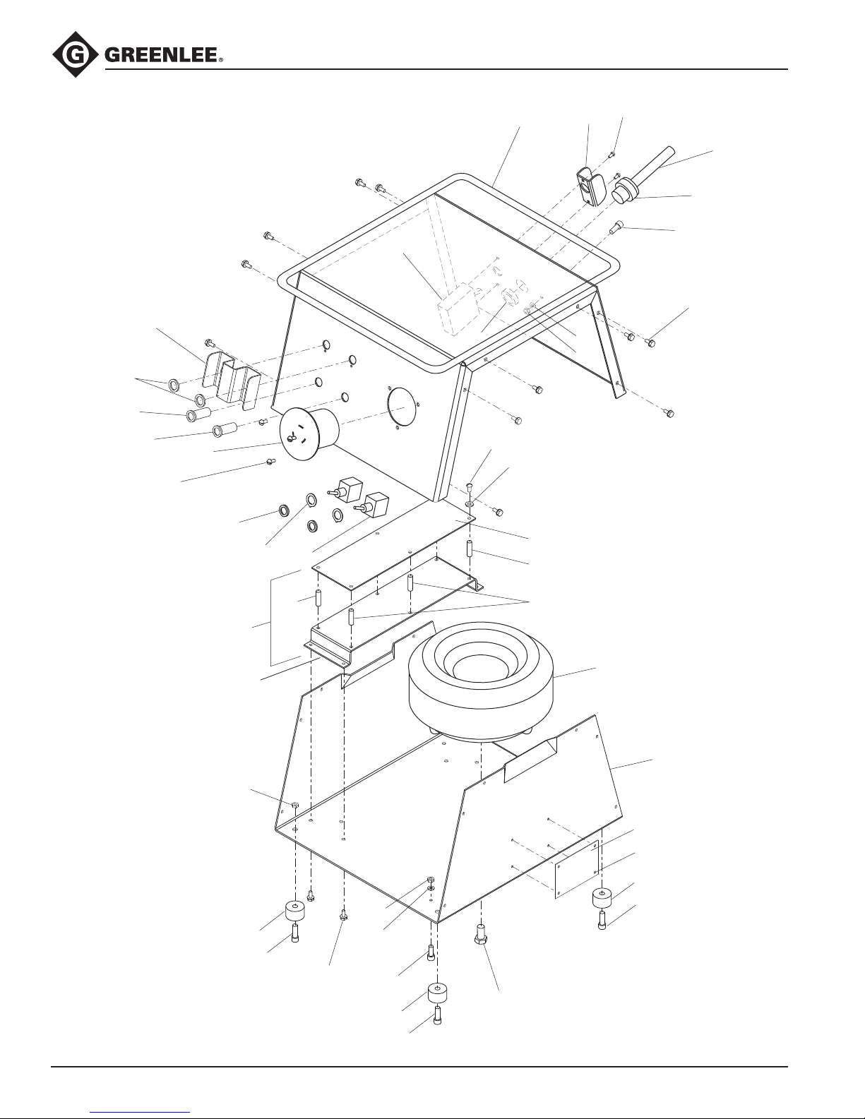
Parts List
Key Part No. Description Qty
1 50035690 Cover ......................................................................................................... 1
2 50297082 Guard, circuit breaker ............................................................................... 1
3 90522036 Screw, machine, #6 – 32 x .250 round head ............................................. 2
4 50035622 Power cord ................................................................................................ 1
5 90541243 Bushing, strain relief .................................................................................. 1
6 91862639 Nut, lock , 1/2" conduit ............................................................................ 1
7 90516451 Screw, cap, #10 – 32 x .500 socket button head .................................... 3
8 90507509 Washer, lock, #10, internal tooth ............................................................... 3
9 90516583 Nut, hex, #10 – 32 ..................................................................................... 3
10 90516559 Screw, thread-forming, #10 – 16 x .500 .................................................. 16
11 91863856 Circuit breaker, 20 amp ............................................................................. 1
12 50046438 Transformer ............................................................................................... 1
13 50035738 Box ............................................................................................................ 1
14 50035762 Plate, identication .................................................................................... 1
15 90530012 Rivet, pop, .125 ......................................................................................... 4
16 50035754 Foot ........................................................................................................... 4
17 90512650 Screw, cap, 1/4 – 20 x .750 socket head ................................................. 4
18 52027081 Screw, cap, 3/8 – 24 x 2.00 hex head ....................................................... 1
19 90526805 Nut, hex, 1/4 – 20 ...................................................................................... 4
20 50047817 Control assembly (includes the next six items) ......................................... 1
20A 90550501 Standoff, threaded, #6 – 32 x .500 ............................................................ 2
20B 50046942 Subplate .................................................................................................... 1
20C 91866448 Support, circuit board ............................................................................... 4
20D 50046390 Circuit board ............................................................................................. 1
20E 90537246 Washer, lock, #6, internal tooth ................................................................. 4
20F 90522036 Screw, machine, #6 – 32 x .250 round head ............................................. 4
21 90550510 Washer, lock, 15/32 internal tooth ............................................................ 2
22 91868904 Ring, locking ............................................................................................. 2
23 91868890 Switch ....................................................................................................... 2
24 90524349 Nut, hex, #8 – 32 ....................................................................................... 3
25 90516494 Washer, lock, #8, internal tooth ................................................................. 3
26 90514408 Screw, machine #8 – 32 x .375 round head .............................................. 3
27 91868548 Receptacle, female ................................................................................... 1
28 91864747 Lamp, red neon ......................................................................................... 1
29 91868866 Lamp, amber neon .................................................................................... 1
30 50035746 Guard, switch ............................................................................................ 1
The following items are not illustrated:
31 50046365 Wire unit, receptacle, black ....................................................................... 1
32 50046373 Wire unit, receptacle, white ....................................................................... 1
33 50046403 Wire unit, lamps ........................................................................................ 1
34 50046411 Wire unit, switches .................................................................................... 1
35 50046420 Wire unit, breaker ...................................................................................... 1
36 50036190 Wire unit, receptacle, relay ........................................................................ 1
37 500 49879 Wire unit, ground bond ............................................................................. 1
38 50035800 Decal ......................................................................................................... 1
39 50303929 Decal, damp warning ................................................................................ 1
Service Kits:
50048848 Adapter cord and plug kit
50062115 Adapter cord kit
50062123 Electric plug kit
Greenlee / A Textron Company 4455 Boeing Dr. • Rockford, IL 61109-2988 USA • 815-397-7070
7
Page 8
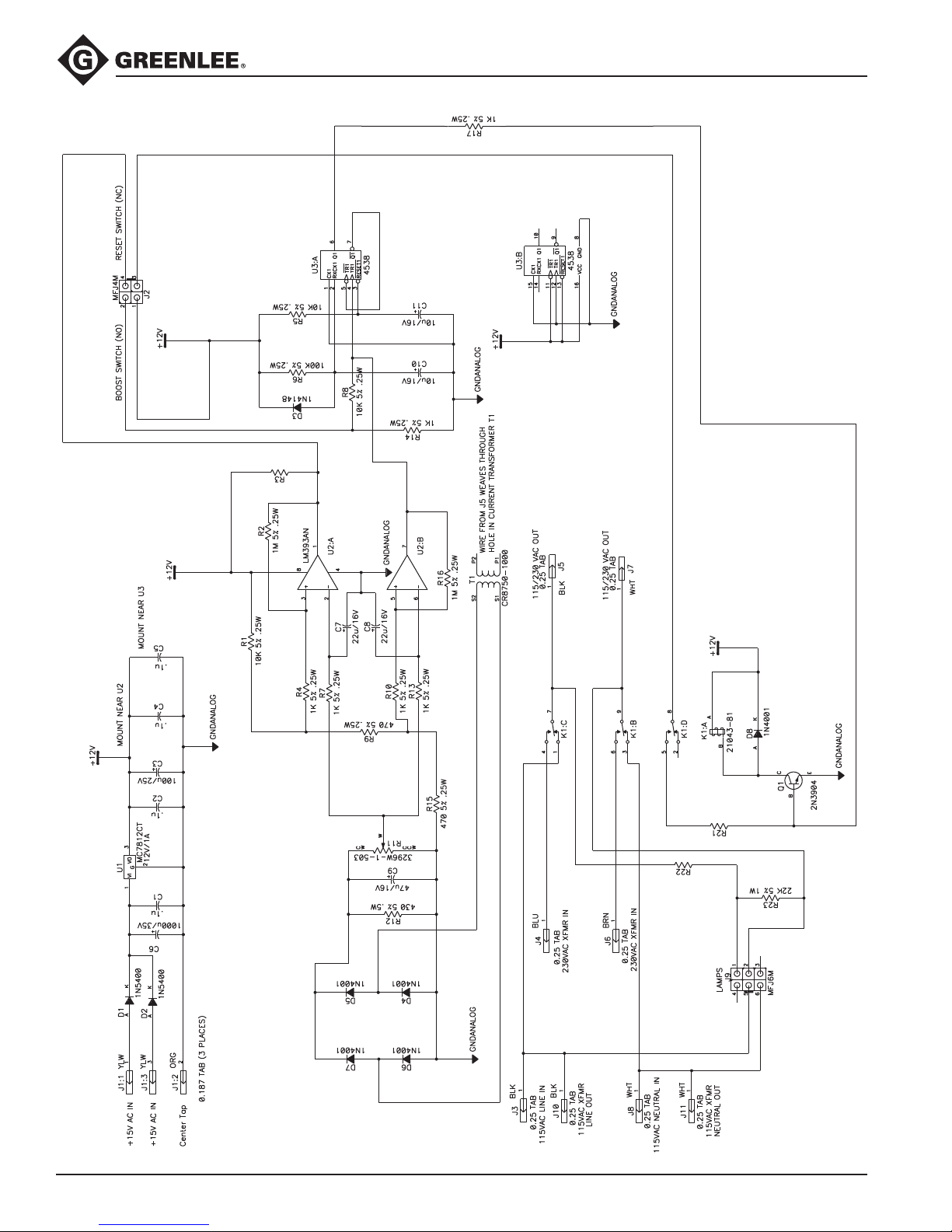
Schematic
4.7K 5% .25W
22K 5% 1W
100 5% .25W
BOOST ON LAMP
(RED)
POWER
ON LAMP
(AMBER)
03561 Speed Booster
Greenlee / A Textron Company 4455 Boeing Dr. • Rockford, IL 61109-2988 USA • 815-397-7070
8
Page 9

03561 Speed Booster
Parts List
Key Supplier Model/Part No. Description Qty
C1, C2, C4, C5 generic Capacitor, .1 µF, 50V .............................................................. 4
C3 generic Capacitor, 100 µF, 25V ...........................................................1
C6 generic Capacitor, 1000 µF, 35V .........................................................1
C7, C8 generic Capacitor, 22 µF, 16V .............................................................2
C9 generic Capacitor, 47 µF, 16V .............................................................1
C10, C11 generic Capacitor, 10 µF, 16V .............................................................2
D1, D2 generic 1N5400 Diode ..................................................................................... 2
D3 generic 1N4148 Diode ..................................................................................... 1
D4 – D8 generic 1N4001 Diode ..................................................................................... 5
J1:1, J1:2, J1:3 Zierick 895 Terminal tab, .187 x .020 ....................................................... 3
J2 Molex 39-28-1043 Connector, Minifit Jr., 4-pin .................................................... 1
J3 – J7, J10 – J11 Keystone 1287 Terminal tab, .250 x .032 ....................................................... 7
J9 Molex 39-28-1063 Connector, Minifit Jr., 6-pin .................................................... 1
K1
Q1 generic 2N3904 Transistor, NPN ......................................................................1
R1, R5, R8 generic Resistor, carbon film, 10 kΩ, 1/4 watt, 5% ............................. 3
R2, R16 generic Resistor, carbon film, 1 MΩ, 1/4 watt, 5% .............................. 2
R3 generic Resistor, carbon film, 4.7 kΩ, 1/4 watt, 5% ............................ 1
R4, R7, R10,
R13, R14, R17 generic Resistor, carbon film, 1 kΩ, 1/4 watt, 5% ............................... 6
R6 generic Resistor, carbon film, 100 kΩ, 1/4 watt, 5% ........................... 1
R9, R15 generic Resistor, carbon film, 470 Ω, 1/4 watt, 5% ............................. 2
R11 Bourns 3296W-1-503 Potentiometer ........................................................................ 1
R12 generic Resistor, carbon film, 430 Ω, 1/2 watt, 5% ............................. 1
R21 generic Resistor, carbon film, 100 Ω, 1/4 watt, 5% ............................. 1
R22, R23 generic Resistor, carbon film, 22 kΩ, 1 watt, 5% ................................2
T1 CR Magnetics CR8750-1000 Current transformer, 1000:1...................................................1
U1 Motorola MC7812CT Integrated circuit .................................................................. 1
(not shown) Wakefield 66725ABPP Heat sink for U1 ..................................................................... 1
Note: Attach U1 to heat sink with a suitable thermal compound.
U2 Motorola LM393AN Integrated circuit ................................................................... 1
U3 generic 4538 Integrated circuit ................................................................... 1
Deltrol Controls
21043-81 Relay, three-pole / double throw ............................................ 1
Greenlee / A Textron Company 4455 Boeing Dr. • Rockford, IL 61109-2988 USA • 815-397-7070
9
Page 10
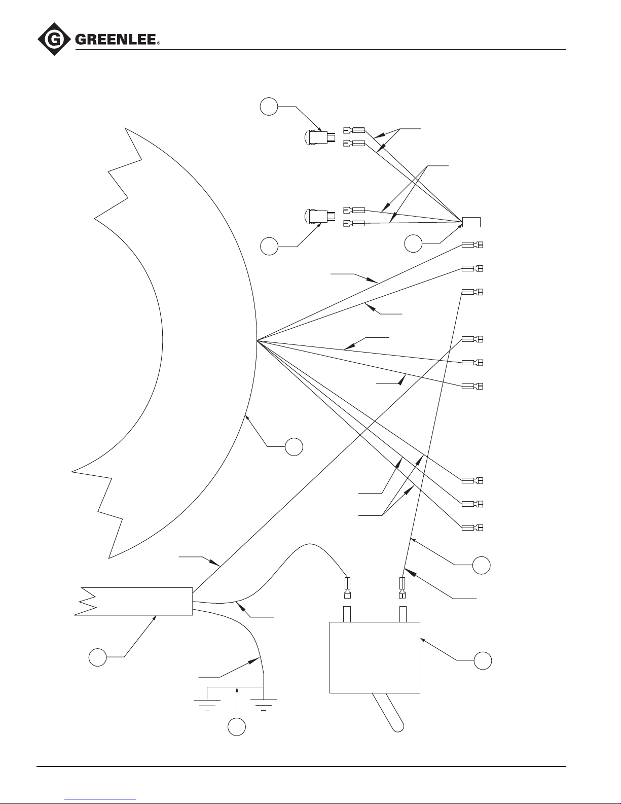
Wiring Diagram
BLACK
BROWN
WHITE
BLACK
BLUE
ORANGE
YELLOW
WHITE
BLACK
GREEN
TO J1:3
TO J1:2
TO J1:1
TO J6
TO J11
TO J8
TO J3
TO J10
TO J4
LOAD
LINE
CHASIS
GROUND
(on box)
CHASIS
GROUND
(on cover)
TO J9
AMBER
“POWER”
RED
“BOOST”
WHITE
BLACK
37
29
28
33
4
11
35
12
03561 Speed Booster
Greenlee / A Textron Company 4455 Boeing Dr. • Rockford, IL 61109-2988 USA • 815-397-7070
10
Page 11
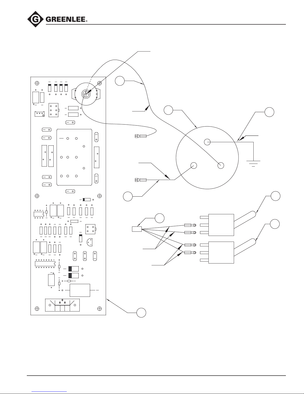
Wiring Diagram
GREEN
WHITE
BLACK
NOTE: Wire must pass through
hole in T1 Coil
1. Assemble switches into cover with lever up.
2. Follow standard ESD procedures for handling control board assembly.
3. Test slip-on connections by tugging slightly after connection.
If the connector is loose on the tab, adjust the connector using
needlenose pliers or similar tool.
4. Potentiometer (R11) should be calibrated and sealed from board supplier.
W
CW
J4
D7
R11
R13
R7
R16
R3
R14
R17
R21
D3
J10
J11
R10
R15
R9
R1
C4
R23
R22
J6
U3
J1
1
2
3
R5
R8
4321
J2
R4
U2
J9
2
654
31
D4
D5
D6
T1
K1
R18
R19
J8
U1
J3
D1 D2
Q1
R20
D8
R6
J5
J7
C5
C2
C3
C10
C11
C6
+
C1
R12
R2
C9
C8
C7
ORG
YLW
YLW
BRN
WHT WHT
GREENLEE/TEXTRON INC.
5004639.0
WHT
BLK
BLU
BLKBLK
REV 1
W
X
Y
CHASIS
GROUND
(on box)
(RESET)
(BOOST)
NOTE: Install receptacle with
brand name to top of unit
TO J5
TO J7
NOTES:
36
31
32
20
27
23
23
34
WHITE
BLACK
TO J2
NOTE: When assembled, the toggle should be pointing up and wired as follows:
Boost: Center Screw and Top Screw
Reset: Center Screw and Bottom Screw
03561 Speed Booster
Greenlee / A Textron Company 4455 Boeing Dr. • Rockford, IL 61109-2988 USA • 815-397-7070
11
Page 12

USA 800-435-0786 Fax: 800-451-2632
815-397-7070 Fax: 815-397-1865
Canada 800-435-0786 Fax: 800-524-2853
International +1-815-397-7070 Fax: +1-815-397-9247
4455 Boeing Drive • Rockford, IL 61109-2988 • USA • 815-397-7070
An ISO 9001 Company • Greenlee Textron Inc. is a subsidiary of Textron Inc.
www.greenlee.com
Printed in USA
 Loading...