

Page 1
INSTRUCTION MANUAL
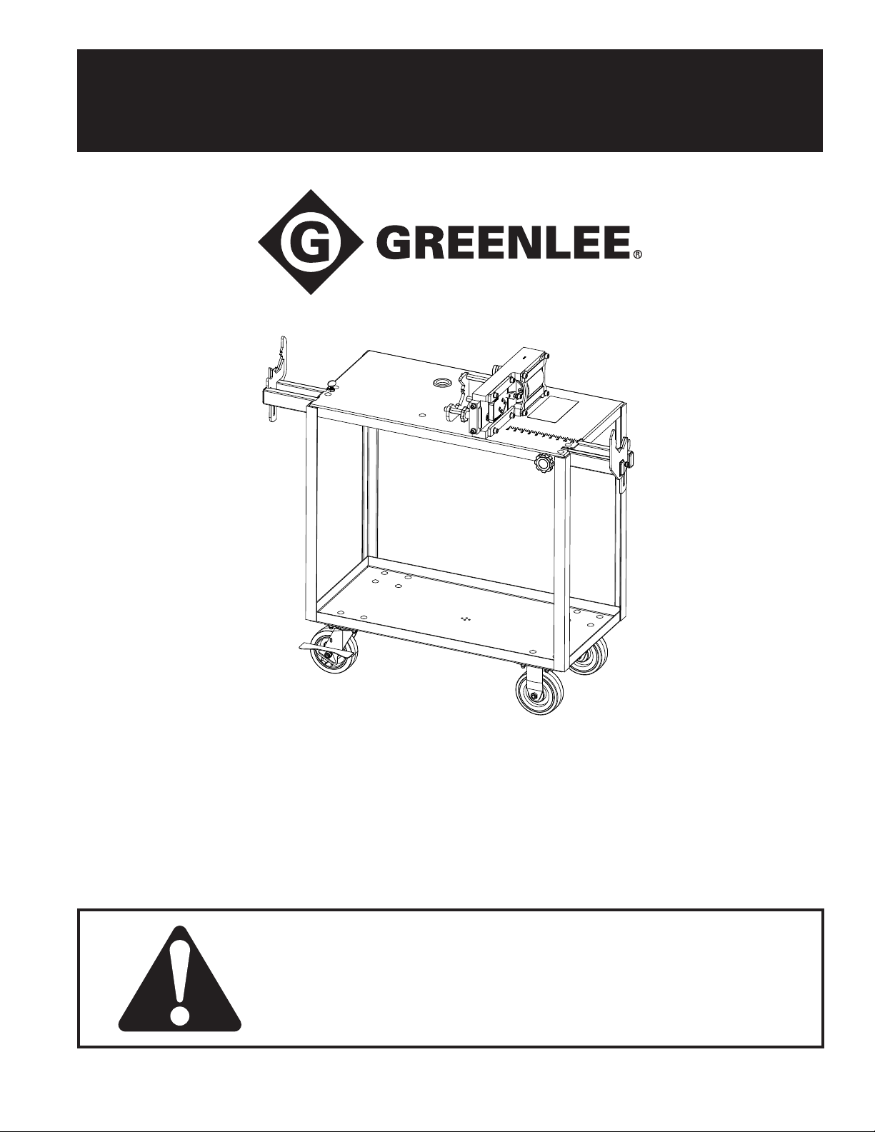
Shear 30T
Shearing Station
Read and understand all of the instructions and
safety information in this manual before operating
or servicing this tool.
52084433 REV5 © 2019 Greenlee Tools, Inc. 11/19
Find Quality Products Online at: [email protected]
www.GlobalTestSupply.com
Page 2

Greenlee Tools, Inc.
Table of Contents
Description .................................................................... 2
Purpose of this Manual ................................................. 2
Safety ............................................................................ 3
Identication .................................................................. 4
Caster Mounting ............................................................ 5
Die Loading/Changeover ............................................... 6
Setting the Measurement Stop ..................................... 7
Operation ..................................................................8–10
Cutting Strut Channel ............................................... 8
Cutting Threaded Rod .............................................. 9
Cutting Angle Iron and Rebar ................................. 10
Maintenance ................................................................ 11
Available Dies .........................................................11–12
Cutting Unit Mounting ................................................. 13
Angle Iron and Rebar Support Installation .................. 14
Angle Iron and Rebar Support Mounting .................... 14
Exploded Views and Parts Lists .............................15–19
Cutting Unit ........................................................15–16
Service Cart .......................................................17–18
Angle Iron and Rebar Support ................................ 21
Shear 30T Shearing StationShear 30T Shearing Station
Description
The Greenlee Shearing Station is used to shear
commonly branded, mild steel strut channel, threaded
rod, angle iron and rebar products. This tool is not
designed to be used with stainless steel, aluminum or
berglass strut or threaded rod workpieces.
Purpose of this Manual
This manual is intended to familiarize all personnel with
the safe operation and maintenance procedures for the
Greenlee Shearing Station.
KEEP THIS MANUAL
2
Find Quality Products Online at: [email protected]
www.GlobalTestSupply.com
Page 3
Greenlee Tools, Inc.
IMPORTANT SAFETY INFORMATION
SAFETY
ALERT
SYMBOL
This symbol is used to call your attention to hazards or
unsafe practices which could result in an injury or
property damage. The signal word, dened below,
indicates the severity of the hazard. The message after
the signal word provides information for preventing
or avoiding the hazard.
Immediate hazards which, if not avoided, WILL result
in severe injury or death.
Shear 30T Shearing Station
Strut channel and threaded rod
ends can be sharp. Gloves are
recommended when handling
these materials.
Skin injection hazard. Do not use
hands to check for oil leaks. Oil under
pressure easily punctures skin. If
injured, seek medical attention immediately to remove oil. Failure to observe
this warning could result in serious
injury or death.
Hazards which, if not avoided, COULD result in severe
injury or death.
Hazards or unsafe practices which, if not avoided, MAY
result in injury or property damage.
Read and understand all of the instructions and safety information in this
manual before operating or servicing
this tool.
Wear eye protection when operating or
servicing this tool. Failure to wear eye
protection could result in serious eye
injury from ying debris or hydraulic oil.
Pinch points: Keep hands away from
the cutting unit during the shearing
process. Failure to observe this warning
could result in severe injury or death.
Do not overload cart
If operating the tool continuously for
more than 2 hours hearing protection
is recommended. Longterm exposure
to high noise levels could result in
hearing damage.
3
Find Quality Products Online at: [email protected]
www.GlobalTestSupply.com
Page 4
Greenlee Tools, Inc.
Identification
Shear 30T Shearing StationShear 30T Shearing Station
4
5
6
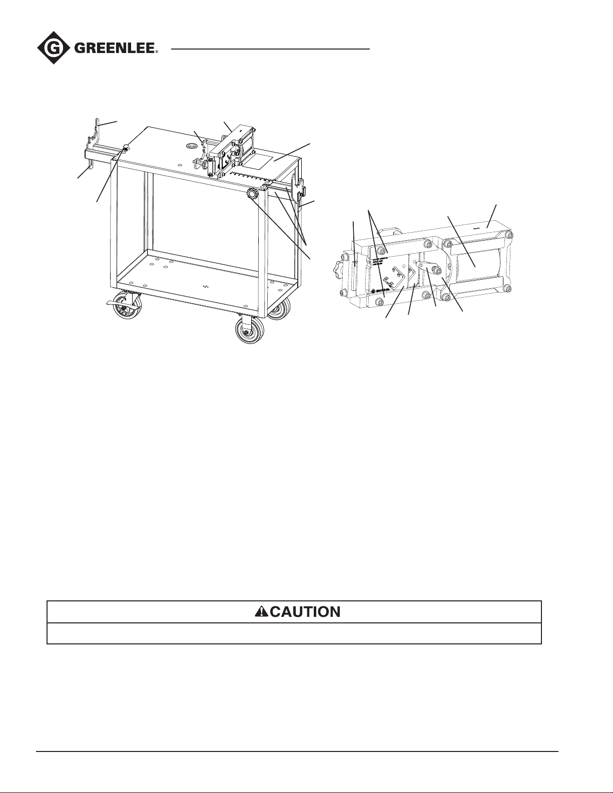
1. Service Cart
2. Cutting Unit
3. Front Material Rest
4. Rear Channel Rest
5. Rear Rod Rest
6. Rear Arm Knob
7. Measurement Stop Knob
8. Extension Arms
2
3
1
9
8
7
13
12
14
15
16
11
17
10
11. 30 Ton Hydraulic Ram with
Universal Coupling
12. Die Retaining Rails
13. End Stop
14. Mobile Die
15. Stationary Die
16. Swing Arm
17. Die Spacer
9. Measurement Stop
10. Alloy Steel Cassette Frame
Specifications
Cutting Unit and Dies
For cutting 18, 16, 14 and 12 gauge mild steel strut channel of various nishes.
For cutting Grade 2 mild or low carbon steel threaded rod of various nishes.
For cutting mild or low carbon steel angle per ASTM A36.
For cutting carbon steel rebar, maximum capacity: #6 (3/4”) grade 60.
The dies are not designed to cut stainless steel workpieces. Expect reduced die life if cutting this material.
Maximum Force ................................................................................................. 30 tons
Hydraulic Pressure ........................................................................................10,000 psi
Service Cart
Dimensions .................................................................................. 19” W x 44” H x50” L
Shelf Size ....................................................................................... 2” H x18” W x 36” L
Load Rating ......................................................................... 800 lbs, evenly distributed
4
Find Quality Products Online at: [email protected]
www.GlobalTestSupply.com
Page 5
Greenlee Tools, Inc.
Caster Mounting
Shear 30T Shearing Station
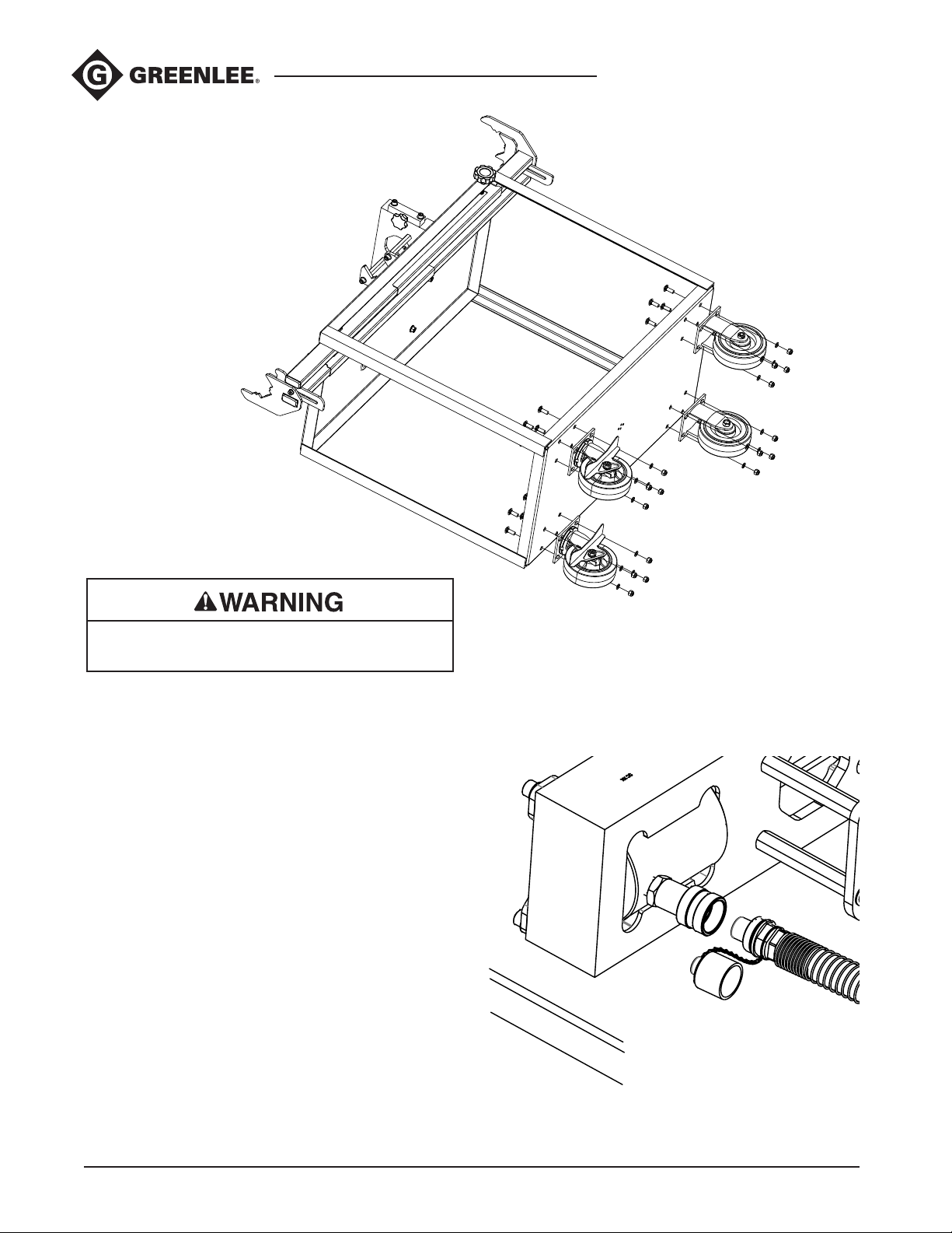
Rotate the Service Cart on its side.
Cart is heavy, advise having two persons when
turning cart.
Attach the Rigid and Swivel Casters to the bottom
shelf of the Service Cart with the included caster
mounting hardware. Torque the nuts to 25 ft lbs.
Reposition the Service Cart with casters in its
upright position.
Transporting and Storage
Remove all dies from the Cutting Unit. Lower the Rear
Rod Rest and Measurement Stop. Center both Extension
Arms; lock the arms by tightening the Rear Arm Knob
and Measurement Stop Knob.
Connecting to Power Source
Attach your 10,000 psi rated pump to the Hydraulic
Ram’s universal coupler with a similarly rated hydraulic
hose. The Service Cart has an opening in its upper
shelf for the hose to feed through if the pump is seated
on the lower shelf. Tighten the hydraulic tting and
test cycle the Cutting Unit unloaded to conrm a
proper connection.
5
Find Quality Products Online at: [email protected]
www.GlobalTestSupply.com
Page 6
Greenlee Tools, Inc.
Die Loading/Changeover
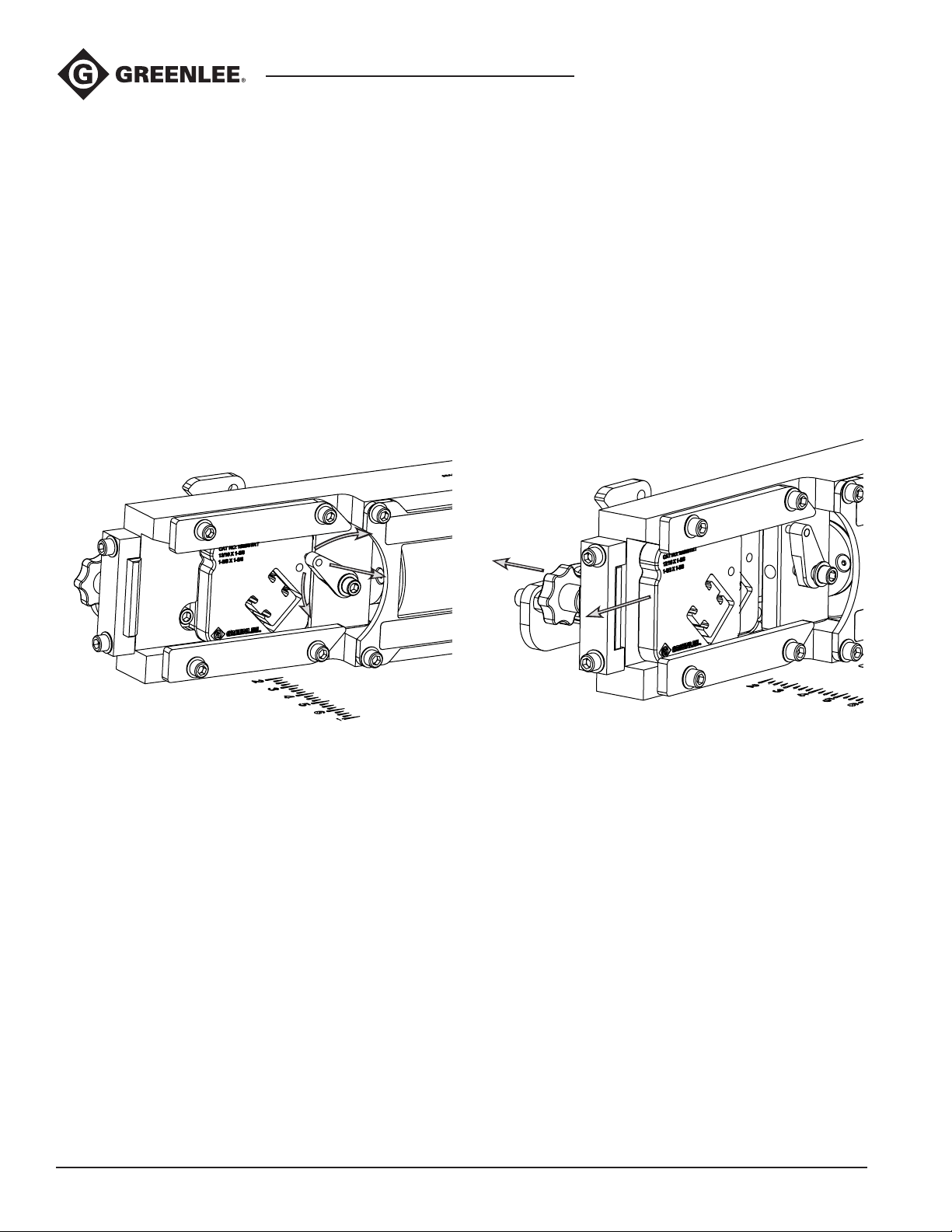
If a die set is already loaded in the cutting unit, pull the
Swing Arm out of the Mobile Die and rotate it onto the
Die Spacer. Pull back the End Stop and slide out the
Mobile Die within the Cassette Frame, then push the
Stationary Die forward and slide it out also. Load the
new die set in a reverse matter. Be sure to reengage the
Swing Arm before beginning cutting.
Note: if having difculty removing or inserting dies, clear
debris from the Cassette Frame die pockets.
Note: it is recommended to apply a moly-base
spray lubricant to the die and frame working surfaces
whenever changing dies.
Shear 30T Shearing StationShear 30T Shearing Station
6
Find Quality Products Online at: [email protected]
www.GlobalTestSupply.com
Page 7
Greenlee Tools, Inc.
Setting the Measurement Stop
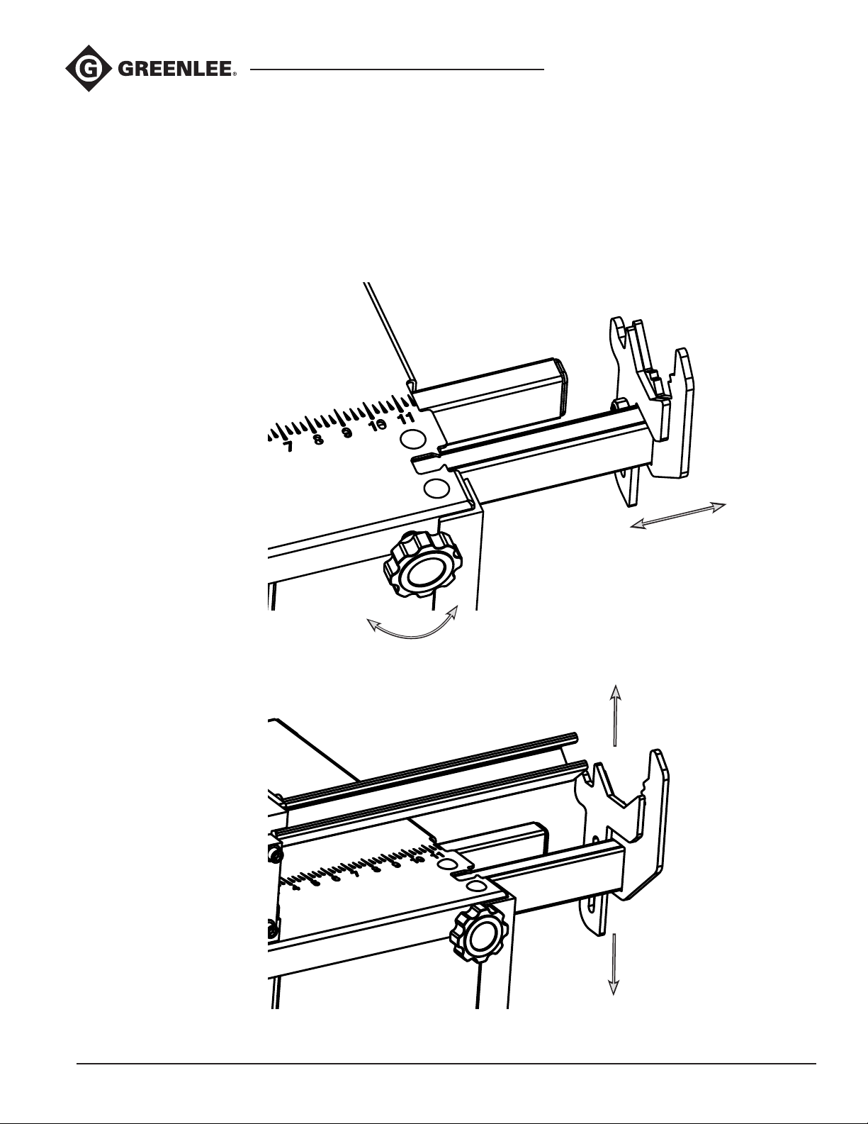
The Measurement Stop can be set to repeatedly cut
lengths from 12 to 48 inches. Turn the Measurement
Stop Knob holding down the Extension Arm counterclockwise to unlock. Set stop to required cut length by
moving the arm left or right as needed, then retighten the
knob. Raise or Lower the stop such that the workpiece
being cut just makes contact.
Shear 30T Shearing Station
7
Find Quality Products Online at: [email protected]
www.GlobalTestSupply.com
Page 8
Greenlee Tools, Inc.
Operation
Engage caster brakes before operating unit.
Cutting Strut Channel
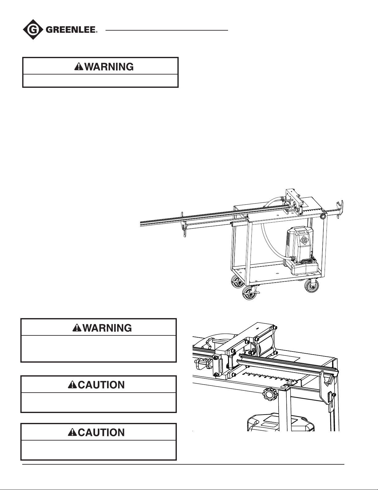
When cutting strut channel, the work piece must always
be supported by the Front Material Rest. Do not cut
total channel lengths of less than 7.5” as they cannot be
properly supported and can cause a die to fracture.
Place the workpiece on the Front Material Rest and Rear
Channel Rest (if long enough) and push through the
Stationary and Mobile dies up to the Measurement Stop
(if being used) or to desired nished length. The Rear
Rod Rest should be lowered out of the way. Activate the
hydraulic pump to begin the cut cycle. Wait for the strut
to shear then release the hydraulic pressure. The Mobile
Die will return to its original position to begin another cut.
Lower the Measurement Stop and unload the nished
workpiece, then return the stop for the next cut.
Shear 30T Shearing StationShear 30T Shearing Station
Note: cutting nished lengths of less than 2 inches may
warp the channel prole.
Note: the Rear Channel Rest was designed to support
up to 10ft workpiece lengths. Additional support may be
required when cutting lengths longer than this.
When cutting short pieces of strut channel the
nished workpiece can pop out due to the shock
of the cutting cycle, always wear safety glasses.
Shearing across holes and slots can leave sharp
points on nished workpieces.
Do not cut single box strut workpieces with the
double strut dies, the dies will fail quickly.
8
Find Quality Products Online at: [email protected]
www.GlobalTestSupply.com
Page 9
Greenlee Tools, Inc.
Operation (cont’d)
Cutting Threaded Rod
Push the workpiece through the Stationary and Mobile
Dies up to the Measurement Stop (if being used) or
to desired nished length. The Rear Rod Rest can be
raised to support longer workpieces. Firmly seat the
rod against the threads of the Stationary Die and keep
the workpiece perpendicular to the dies. Activate the
hydraulic pump to begin the cut cycle. Wait for the rod
to shear then release the hydraulic pressure. The Mobile
Die will return to its original position to begin another
cut. Lower the Measurement Stop and unload the
nished workpiece, then return the stop for the next cut.
Note: The threaded rod dies have been designed so that
the nut threads onto the cut rod by hand. Thread quality,
surface nish (i.e., galvanized or plated), dirt and scale
could affect the ability of the nut to thread freely onto the
cut rod.
Filing of the rod end or use of a pliers may be necessary
if nut does not easily thread on due to these factors.
Shear 30T Shearing Station
Note: The Rear Rod Rest was designed to support
single workpieces up to 10ft lengths. Additional support
may be required when cutting lengths longer than this or
multiple pieces at once.
Tip: If a nut begins to thread and locks up, tapping
it on a surface will often loosen it and allow
continued threading.
Finished workpiece length should not be less than .25”.
9
Find Quality Products Online at: [email protected]
www.GlobalTestSupply.com
Page 10
Greenlee Tools, Inc.
Operation (cont’d)
Engage caster brakes before operating unit.
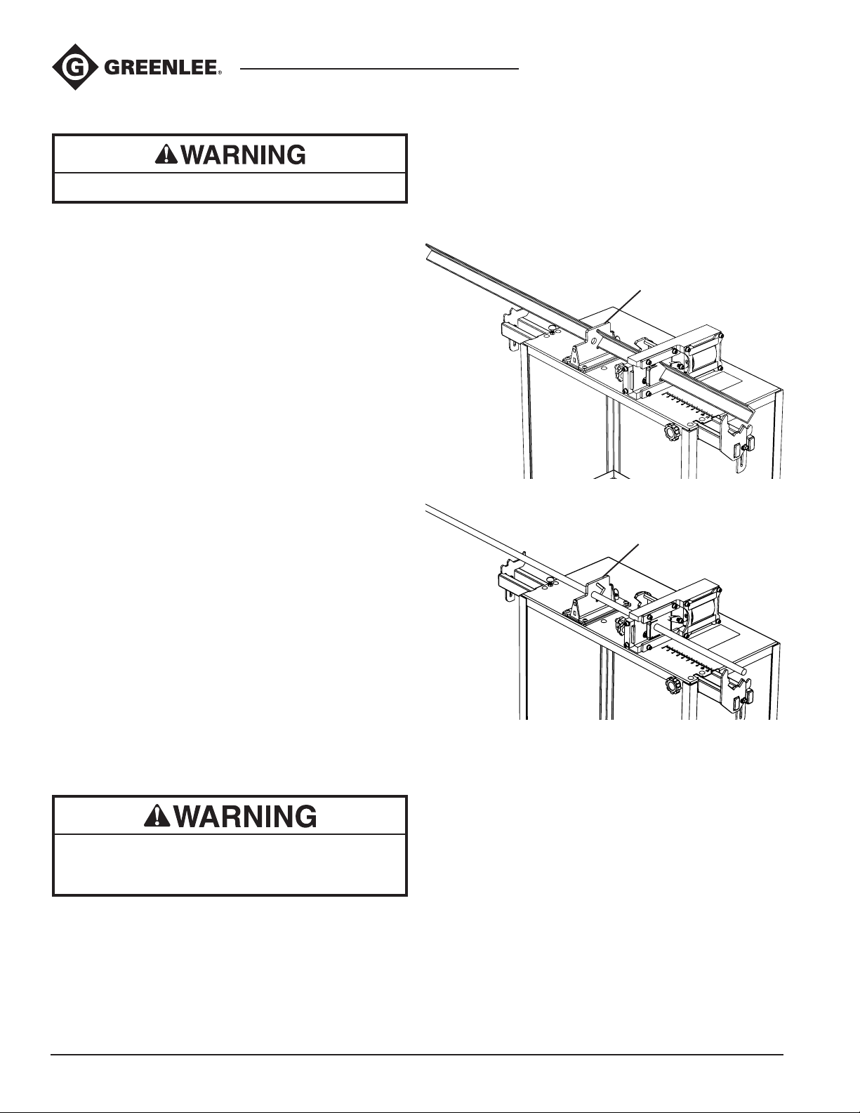
Cutting Angle Iron (Steel Angles) and Rebar
Note: When cutting angle iron and rebar, the reaction
force on the ends of the workpiece can be severe.
Always use the Rear Support to secure the workpiece
when cutting angle iron and rebar. The current Rear
Channel Rest will not provide sufcient support and
damage to the Rear Channel rest will occur if not
properly supported.
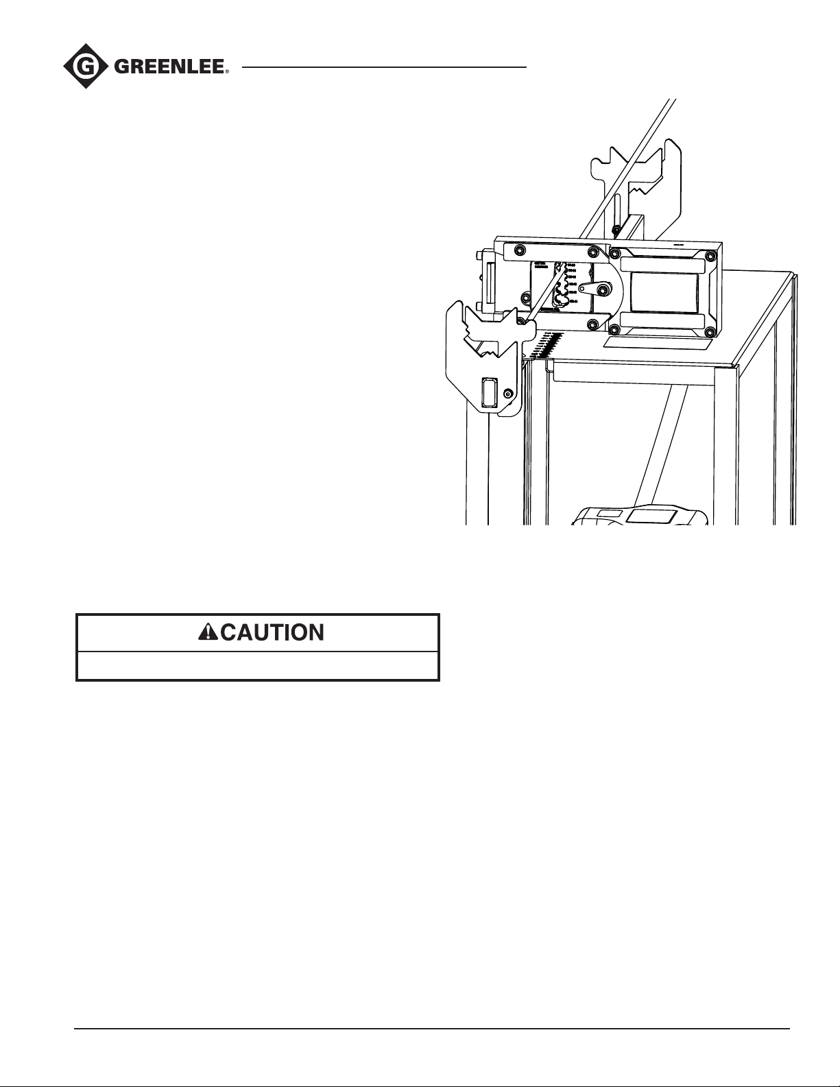
Lower the Rear Channel Rest and push the angle iron
or rebar through the Rear Support and then through
the Stationary and Mobile Dies up to the measurement
stop (if being used) or to the desired nished length.
Provide support to the free end of the angle iron or rebar,
keeping it perpendicular to the dies, to prevent the piece
from falling. Activate the hydraulic pump to begin the
cut cycle. Wait for the angle iron or rebar to shear then
release the hydraulic pressure. The Mobile Die will automatically return to its original position to begin another
cut. Lower the Measurement Stop and unload the nished workpiece, then return the stop for the next cut.
Note: The Rear Channel Rest was designed to support
up to 10 foot workpiece lengths. Additional support may
be required when cutting lengths longer than this.
Note: Cutting angle iron and rebar will require more
frequent cleaning in the track portions of the Cassette
Frame and Die Retaining Rails. Scale on the surface
of the angle iron and rebar will fall during cutting and
accumulate in the unit. See maintenance instructions
for cleaning.
Note: To remove the Rear Support when it is not
in use, disengage the plunger by pulling up the key
ring and slide the Support Frame out. To use the Rear
Support again, lift the key ring and slide the Support
Frame into the Support Base. Release the key ring and
make sure that the Support Frame is secure in place.
Shear 30T Shearing StationShear 30T Shearing Station
Rear Support
Rear Support
When cutting short pieces of angle iron or rebar the
nished workpiece can pop out due to the shock
of the cutting cycle, always wear safety glasses.
10
Find Quality Products Online at: [email protected]
www.GlobalTestSupply.com
Page 11
Greenlee Tools, Inc.
Shear 30T Shearing Station
Maintenance
Lock out power to the Cutting Unit before performing any maintenance.
Change the hydraulic oil annually or after 10,000 cycles. Use ASTM 215 hydraulic uid (or equal).
At least monthly, clean the inner track portions of the Cassette Frame and Die Retaining Rails. Apply a moly based, spray
lubricant to the working surfaces. A dry lm lubricant such as Molykote 557 is recommended.
The material cutting dies are wear parts and will fail over time. Order additional dies through Greenlee distributors.
The unit experiences a shock during each cutting cycle which can loosen bolt connections over time. Periodically check all
fasteners on the Cutting Unit and retighten where needed.
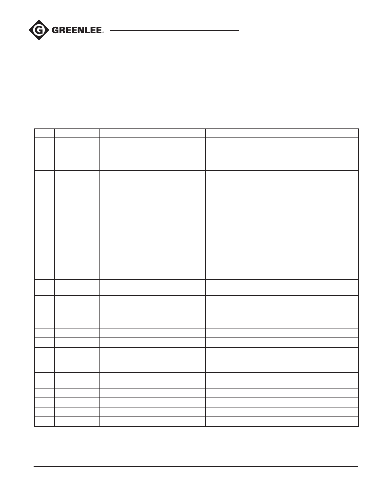
Available Dies
KEY CAT NO. DESCRIPTION COMPATIBILITY
1 1316SSTRT 13/16 X 1-5/8 Single box prole B-Line B52, B54, & B56
Unistrut P4520, P4100, & P4000
Powerstrut PS 520 & PS 500
Superstrut B-1200 & B-1400
2 78SSTRT 7/8” x 1-5/8 Single box prole Unistrut P3300
3 158STRDSTRT 1-5/8 x 1-5/8 Single box prole B-Line B22, B24, & B26
Unistrut P1000, P1100, & P2000
Powerstrut PS 200 & PS 210
Superstrut A-1200 & A-1400
4 158SSTRT 13/16 x 1-5/8 & 1-5/8 x 1-5/8 Single
box proles
5 1316DSTRT 13/16 x 1-5/8 Double box
back-to-back prole
6 78DSTRT 7/8 x 1-5/8 Double box
back-to-back proles
7 158DSTRT 1-5/8 X 1-5/8 Double box
back-to-back proles
8 4STRT21 1-1/16 x 2-1/8 Single box 4D proles B-Line 4D21
9 4STRT22 2-1/8 x 2-1/8 Single box 4D proles B-Line 4D22
10 1458TROD 1/4-20, 3/8-16, 1/2-13 & 5/8-11
Threaded Rod
11 GSDR15 32 x 15mm G-Type DIN Rail proles TS-32 (G)
12 THDR7515 35 x 7.5mm & 35 x 15mm DIN Rail
Combo proles
13 3000SSRB 3000 Series Steel Raceway Base prole Legrand G3000B, V3000B
14 3000SSRC 3000 Series Steel Raceway Cover prole Legrand G3000CE, V3000B
15 14ANG-KIT Angle Iron dies with Rear Support Mild steel in sizes up to 2”x 2” and 1/4” maximum thickness
16 26RBR-KIT Rebar dies with Rear Support Grade 60 Rebar in sizes up to #6 (3/4”)
B-Line B22, B24, B26 & B52, B54, B56
Unistrut P1000, P1100, P2000 & P4520, P4100, P4000
Powerstrut PS 200, PS 210 & PS 520, PS 500
Superstrut A-1200, A-1400 & B-1200, B-1400
B-Line B52A, B54A, B56A
Unistrut P4001, P4101, P4521
Powerstrut PS 500 2T3, PS 520 2T3, PS 560 2T3
Superstrut B-1202 & B-1402
Unistrut P3301
B-Line B22A, B24A, B26A
Unistrut P1001, P1101, P2001
Powerstrut PS 200 2T3, PS 210 2T3
Superstrut A-1202 & B-1202
All mild steel rod
TS-35 (7.5mm), TS-35 (15mm)
*Support required for angle iron and rebar dies
**See replacement parts for individual angle iron and rebar dies (page 21)
11
Find Quality Products Online at: [email protected]
www.GlobalTestSupply.com
Page 12
Greenlee Tools, Inc.
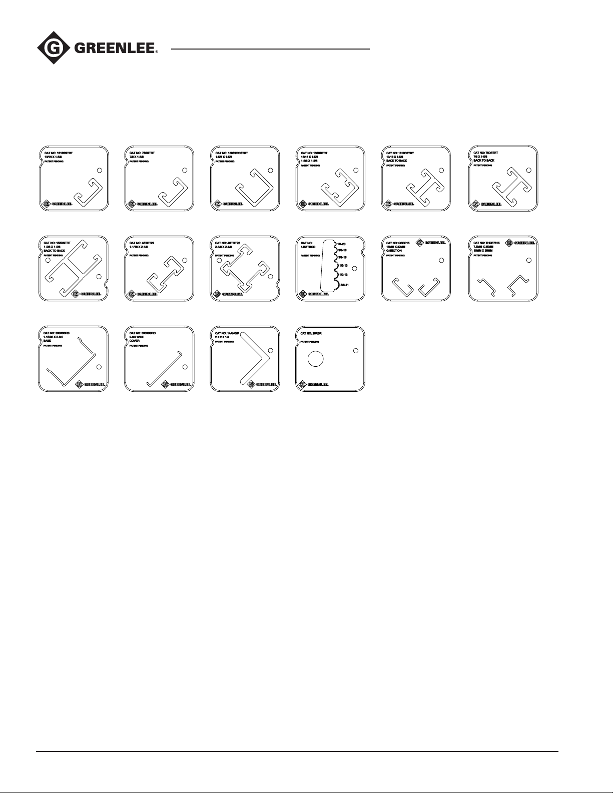
Available Dies (cont’d)
Shear 30T Shearing StationShear 30T Shearing Station
1
7
13 14
Note: The hot-dipped galvanized nished available from many manufacturers will often leave beads of nish on the product and
can be more difcult to get through dies.
2
8
3
9
15
10
16
4
5 6
11 12
12
Find Quality Products Online at: [email protected]
www.GlobalTestSupply.com
Page 13
Greenlee Tools, Inc.
Cutting Unit Mounting
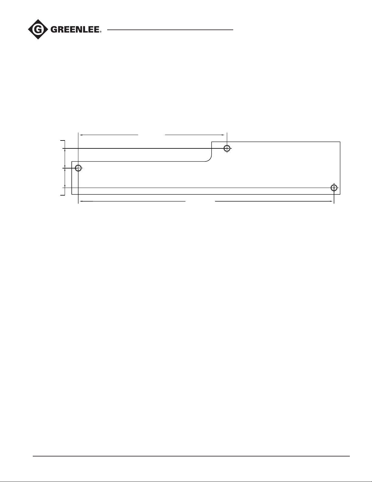
To mount the Cutting Unit to another surface, rst
unfasten the three 3/8-16 by 5/8” long hex bolts
underneath the top shelf of the service cart to free
the unit.
The following bolt pattern will be required on the new
surface. Longer bolts may be needed if attaching the unit
to a surface thicker than 12 gauge (.105 steel).
8.500
1.125
Shear 30T Shearing Station
1.125
14.619
13
Find Quality Products Online at: [email protected]
www.GlobalTestSupply.com
Page 14
Greenlee Tools, Inc.
Installation Instructions – Angle Iron
and Rebar Support
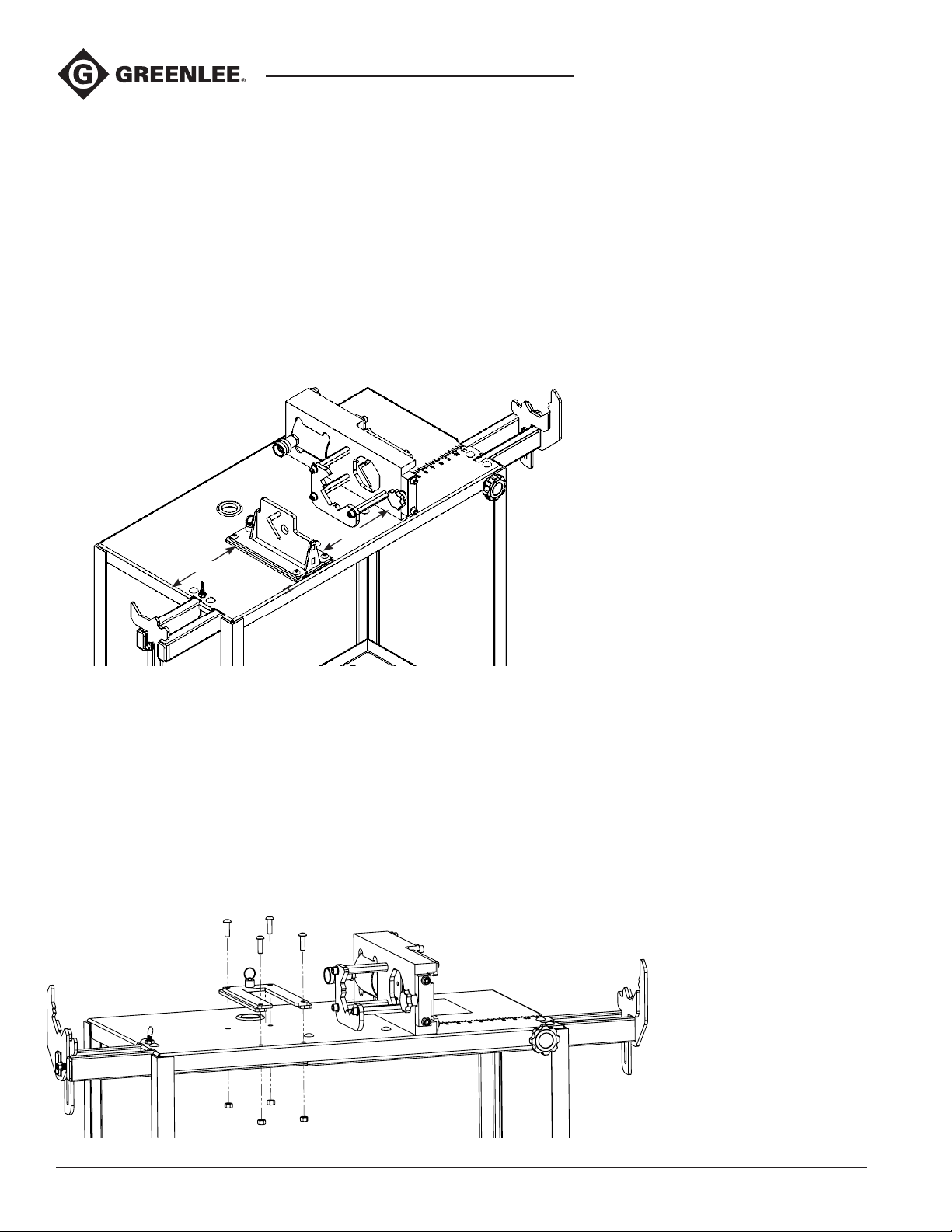
Please follow the directions below to create the mounting holes for the Rear Support. If your service cart
already has holes drilled for the Rear Support please
skip to the mounting instructions.
Use the base as a template and locate the base 8.75”
from the left side of the cart (see below). Line up the left
side of the base with this line. Mark a line .25” from the
front of the cart (see below). Line up the front of the base
with the 0.25” mark.
Using a marker/pencil, trace the holes on the Support
Base. Drill the four holes using a 13/32” drill bit.
Shear 30T Shearing StationShear 30T Shearing Station
9.125”
8.750”
0.250”
Angle Iron and Rebar
Support Mounting
To mount the Angle Iron and Rebar Support to the cart,
rst line up the Support Base with the holes on the cart
and bolt the Support Base down using four 3/8-16 by
1.25” socket head cap screws and four 3/8-16 hex nuts.
See the image below.
Using the Loctite threadlocker capsule, apply threadlocker to each screw and tighten down to a torque
of 35 ft-lbs.
14
Find Quality Products Online at: [email protected]
www.GlobalTestSupply.com
Page 15
Greenlee Tools, Inc.
Exploded Views and Parts Lists
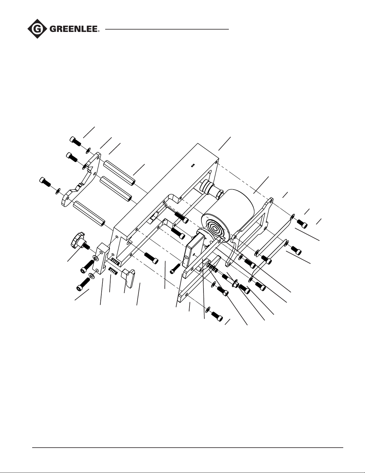
Exploded View – Cutting Unit
1A
Shear 30T Shearing Station
2F
2E
2D
2C
1B
1C
2B
2A
1D
1E
3N
3M
3L
3K
5
4A
3A
3B
3C
3D
3E
3F
3G
3H
3I
3J
Note: Torque 3/8 screws to 35ft lbs and 1/4 screws to 10ft lbs.
15
Find Quality Products Online at: [email protected]
www.GlobalTestSupply.com
Page 16

Greenlee Tools, Inc.
Exploded Views and Parts Lists (cont’d)
Exploded View – Cutting Unit
Key Part No. Description Qty
1 52084465 Material Rest Kit ....................................................................................1
1A Socket Head Cap Screw, 3/8-16 x 7/8 L ...............................................3
1B Bellville Washer, .38 ID x 3/4 OD ...........................................................3
1C Front Material Rest ................................................................................1
1D Standoff, 3/8-16 x 4 L ............................................................................3
1E Socket Head Cap Screw, 3/8-16 x 1-1/4 L ...........................................4
2 52084466 End Stop Kit ..........................................................................................1
2A End Stop ................................................................................................1
2B Compression Spring, .36 OD x 1 L ........................................................ 2
2C Slide Block .............................................................................................1
2D Bellville Washer, .38 ID x 3/4 OD ...........................................................2
2E Socket Head Cap Screw, 3/8-16 x 1-1/2 L ...........................................2
2F* Lobed Knob, 3/6-16 x 11/16 L ..............................................................1
Shear 30T Shearing StationShear 30T Shearing Station
3 52084467 Working Components Kit.......................................................................1
3A Faceplate ...............................................................................................1
3B Bellville Washer, .38 ID x 3/4 OD ........................................................... 8
3C Socket Head Cap Screw, 3/8-16 x 3/4 L ...............................................4
3D Identication Decal, Upper .................................................................... 1
3E Piston Rod Adapter ............................................................................... 1
3G Flat Head Screw, 1/4-20 x 1/2 L ............................................................ 2
3H Flanged EGL Screw, 3/8-16 x 1-5/8 L ...................................................1
3I Compression Spring, .455 OD x 1-1/4 L ...............................................1
3J Swing Arm Assembly .............................................................................1
3K Socket Head Cap Screw, 3/8-24 x 7/8 L ...............................................4
3M Die Retaining Rail ..................................................................................2
3N* SEMS Screw, ¼-20 x 1-1/4 L ................................................................1
4 52084464 Cylinder Kit ............................................................................................1
4A Hydraulic Cylinder, 30 Ton ..................................................................... 1
5 Cassette Frame .....................................................................................1
6 52084463 Cylinder Seal Kit ....................................................................................1
Seal Kit for Hydraulic Cylinder ...............................................................1
6A**
*Fastened with threadlocking adhesive .................................................................................................................
**Not shown
16
Find Quality Products Online at: [email protected]
www.GlobalTestSupply.com
Page 17
Greenlee Tools, Inc.
Exploded Views and Parts Lists (cont’d)
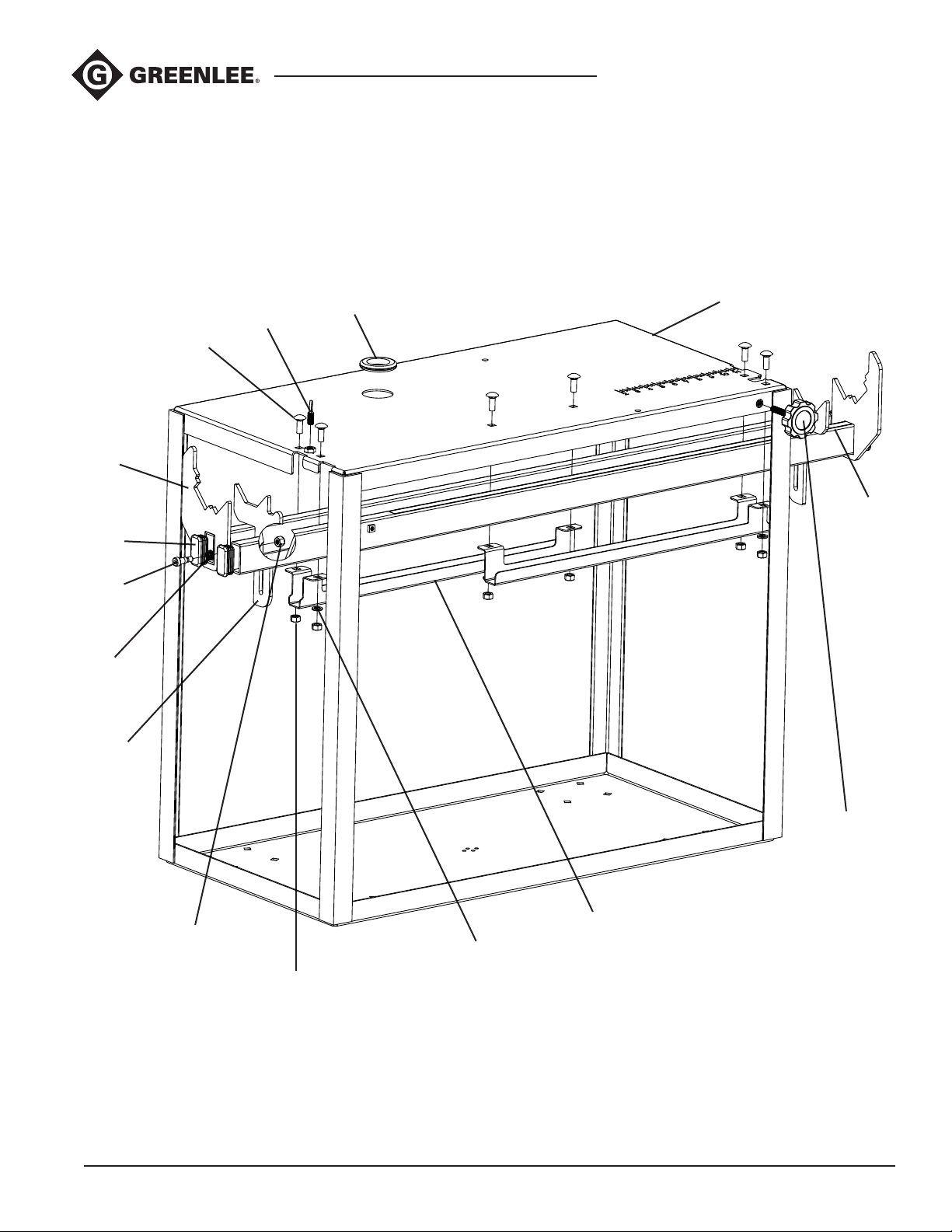
Exploded View – Service Cart
Shear 30T Shearing Station
1G
1D
1E
1F
1C
1B
1A
2
1N
1H
1M
1L
1I
1J
1K
17
Find Quality Products Online at: [email protected]
www.GlobalTestSupply.com
Page 18

Exploded Views and Parts Lists (cont’d)
Exploded View – Service Cart
Key Part No. Description Qty
1 52084468 Cart Components Kit .............................................................................1
1A Grommet, 1-1/2 ID x 2-3/8 OD ..............................................................1
1B Screw, Spade, 3/8-16 x 3/4 L ................................................................1
1C* Carriage Bolt, 3/8-16 x 1 L ....................................................................3
1D* Extension Arm Weldment ......................................................................1
1E* Rectangular Plug, 1 W x 2 L ..................................................................2
1F* Hex Head Flange Screw, 3/8-16 x 1 L ...................................................1
1G* Disc Spring, .480 ID x .6 OD ..................................................................1
1H* Rear Rod Rest / Measurement Stop .....................................................1
1I* Hex Lock Nut, 3/8-16 x 17/64 W ........................................................... 1
1J Hex Nut, 3/8-16 x 9/16 W ......................................................................3
1K* Lock Washer, .385 ID x .665 OD ............................................................3
1L* Slide Plate .............................................................................................. 1
1M Measurement Decal ...............................................................................1
1N Fluted Knob, 3/8-16 x 2 L ......................................................................1
1O Branding Decal ......................................................................................1
Shear 30T Shearing StationShear 30T Shearing Station
2 Cart Weldment .......................................................................................1
3 52082768 Caster Kit ...............................................................................................1
3A** Locking Swivel Caster, 6 D .................................................................... 2
3B** Rigid Caster, 6 D ....................................................................................2
3C** Carriage Bolt, 3/8-16 x 1 L .................................................................. 16
3D** Flat Washer, .39 ID x 5/8 OD ............................................................... 16
3E** Hex Lock Nut, 3/8-16 x 9/16 W ........................................................... 16
*These parts can be used in either Extension Arm position, order two Cart Components Kits if both
Arms must be replaced
**Not shown, see Caster Mounting section of the manual
Find Quality Products Online at: [email protected]
www.GlobalTestSupply.com
Page 19
Greenlee Tools, Inc.
Exploded Views and Parts Lists (cont’d)
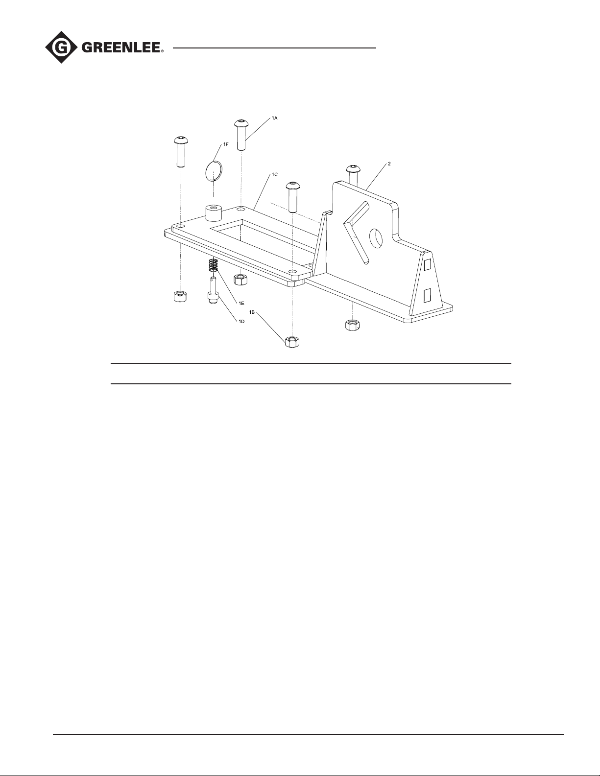
Exploded View – Angle Iron and Rebar Support
Shear 30T Shearing Station
Key Part No. Description Qty
52087961 Support Frame and Base Kit (includes items 1+2) .................................
1A Screw-Cap 3/8-16 x 1.25 SKT BTN HD ................................................4
1B Nut-Hex 3/8-16 ......................................................................................4
1C Base Weldment......................................................................................1
1D Plunger ..................................................................................................1
1E Spring Compression .............................................................................. 1
1F Key Ring ................................................................................................ 1
1G* Threadlocker Capsule ............................................................................1
2 52087876 Rear Support Frame ..............................................................................1
52087877 Plunger Repair Kit (includes items 1D, 1E, 1F) .......................................
Replacement Dies
52086316 Angle Iron Dies .......................................................................................
52086401 Rebar Dies ..............................................................................................
*Not shown
19
Find Quality Products Online at: [email protected]
www.GlobalTestSupply.com
 Loading...