

Page 1
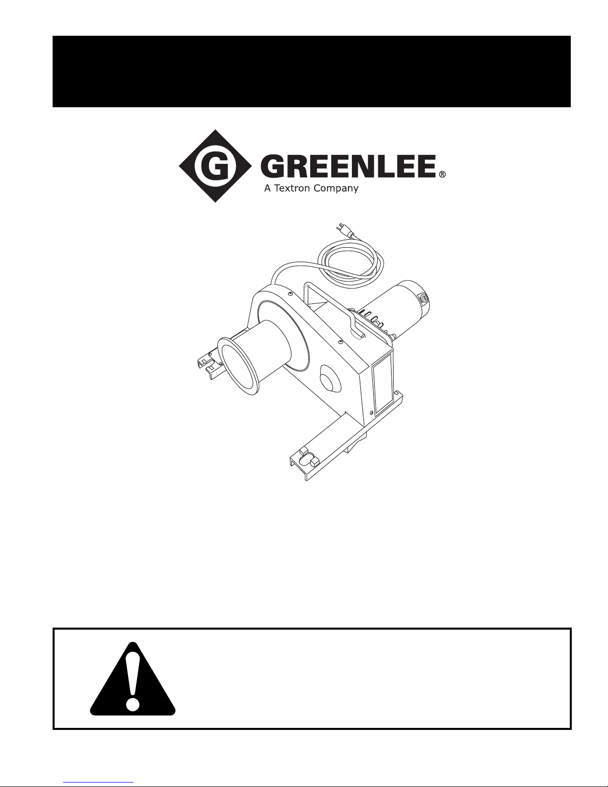
INSTRUCTION MANUAL
2001-Series
Easy Tugger® Cable Pullers
Effective with Serial Code VL for 115 Volt Pullers
and Serial Code VA for 220 Volt Pullers
99978245 © 2006 Greenlee Textron Inc. IM 979 REV 9 2/06
Read and understand all of the instructions and
safety information in this manual before operating
or servicing this tool.
Page 2

2001-Series Easy Tugger Cable Pullers
Table of Contents Description
Description ..................................................................... 2
Safety .............................................................................2
Purpose .......................................................................... 2
Important Safety Information .......................................3-5
Grounding Instructions ...................................................6
Identification ...................................................................7
Specifications .................................................................8
Cable Pulling Glossary ................................................... 9
Cable Pulling Principles ............................................... 10
Cable Pulling Systems........................................... 10
Pulling Theory........................................................ 11
Cable Pulling Forces ........................................12-16
Tailing the Rope .................................................... 17
Summary of Cable Pulling Principles .................... 18
Planning the Pull .......................................................... 18
Typical Setups.........................................................19-21
Setup and Operation ...............................................22-23
Removing Cable........................................................... 24
Dual Pulling ..................................................................25
Maintenance............................................................26-28
Troubleshooting ........................................................... 29
Exploded Views and Parts Lists .............................. 30-34
Wiring Diagrams........................................................... 35
The Greenlee Easy Tugger® cable puller is intended to
be used to pull cable through conduit and in tray. The
Easy Tugger will develop 8.89 kilo-Newtons (2000 lb)
of pulling force. See a Greenlee catalog for sheaves,
pulling rope, and other cable pulling accessories rated
for use with the Easy Tugger to create an entire cable
pulling system.
No single manual can provide instructions for every
cable pulling application. This manual contains general
information for pulling cable. Illustrations of some typical
setups are also provided.
Safety
Safety is essential in the use and maintenance of
Greenlee tools and equipment. This instruction manual
and any markings on the tool provide information for
avoiding hazards and unsafe practices related to the
use of this tool. Observe all of the safety information
provided.
Purpose
This manual is intended to familiarize operators and
maintenance personnel with Greenlee 2001-series
Easy Tugger cable pullers.
Keep this manual available to all personnel.
Greenlee / A Textron Company 2 4455 Boeing Dr. • Rockford, IL 61109-2988 USA • 815-397-7070
All specifications are nominal and may change as design improvements occur. Greenlee Textron Inc. shall not be liable for damages
resulting from misapplication or misuse of its products.
Mobilgrease is a registered trademark of Mobil Oil Corporation.
KEEP THIS MANUAL
Page 3
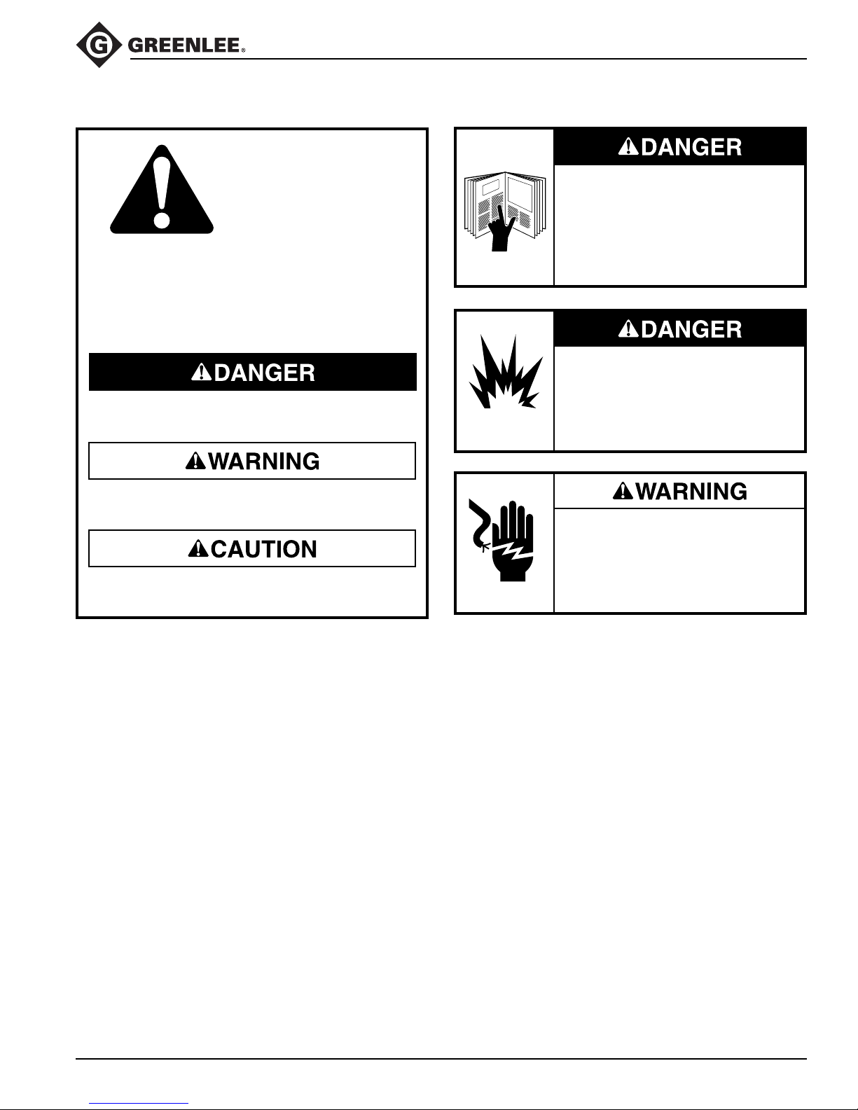
IMPORTANT SAFETY INFORMATION
SAFETY
ALERT
SYMBOL
This symbol is used to call your attention to hazards
or unsafe practices which could result in an injury
or property damage. The signal word, defined
below, indicates the severity of the hazard. The
message after the signal word provides information
for preventing or avoiding the hazard.
Immediate hazards which, if not avoided, WILL
result in severe injury or death.
2001-Series Easy Tugger Cable Pullers
Read and understand all of the
instructions and safety information
in this manual before operating or
servicing this tool.
Failure to observe this warning will
result in severe injury or death.
Do not operate the cable puller in a
hazardous environment. Hazards
include flammable liquids and gases.
Failure to observe this warning will
result in severe injury or death.
Hazards which, if not avoided, COULD result in
severe injury or death.
Hazards or unsafe practices which, if not avoided,
MAY result in injury or property damage.
Electric shock hazard:
Disconnect the cable puller from
the power supply before servicing.
Failure to observe this warning could
result in severe injury or death.
Greenlee / A Textron Company 3 4455 Boeing Dr. • Rockford, IL 61109-2988 USA • 815-397-7070
Page 4
2001-Series Easy Tugger Cable Pullers
IMPORTANT SAFETY INFORMATION
Inspect all components of the cablepulling system. Verify the maximum
load-bearing capacity or maximum
strength of all structural supports,
pulling system components and
anchoring systems before setting
up the puller. Any component that
cannot withstand the maximum cablepulling forces may break and strike
nearby personnel with great force.
Failure to observe this warning could
result in severe injury or death.
Do not allow anything other than the
pulling rope to contact the capstan.
A grip, swivel, or other component
could break and strike nearby
personnel with great force.
Failure to observe this warning could
result in severe injury or death.
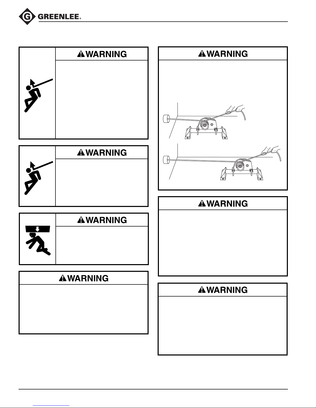
Locate the puller so that it is close to the conduit.
Rope, cable, or connectors can break under tension,
causing the rope to whip violently.
Failure to observe this warning could result in severe
injury or death.
X
Do not stand directly under a vertical
pull. Cable could fall suddenly from the
conduit, injuring nearby personnel.
Failure to observe this warning could
result in severe injury or death.
Do not operate puller if the anti-reverse mechanism
is not working. If you do not hear the clicking of
the anti-reversing pawl when the capstan is rotating,
shut the puller off and have it repaired by an
authorized Greenlee service center.
Failure to observe this warning could result in severe
injury or death.
An underrated rope may break and whip violently.
Use a double-braided composite rope with the
following characteristics:
• Maximum Rated Capacity:
at least 8.89 kN (2000 lb)
• Average Breaking Strength:
at least 35.6 kN (8000 lb)
Failure to observe this warning could result in severe
injury or death.
• Check the condition of the entire rope before use.
A worn or damaged rope can break under tension
and whip violently.
• Do not maintain a stationary rope on a rotating
capstan. The wear generated may cause the rope
to break under tension and whip violently.
Failure to observe these warnings could result in
severe injury or death.
Greenlee / A Textron Company 4 4455 Boeing Dr. • Rockford, IL 61109-2988 USA • 815-397-7070
Page 5
2001-Series Easy Tugger Cable Pullers
IMPORTANT SAFETY INFORMATION
Attach the pulling rope to the cable with appropriate
types of connectors as described in this manual.
Select connectors with a maximum rated capacity
of at least 8.89 kN (2000 lb). An underrated connector can break under tension.
Failure to observe this warning could result in severe
injury or death.
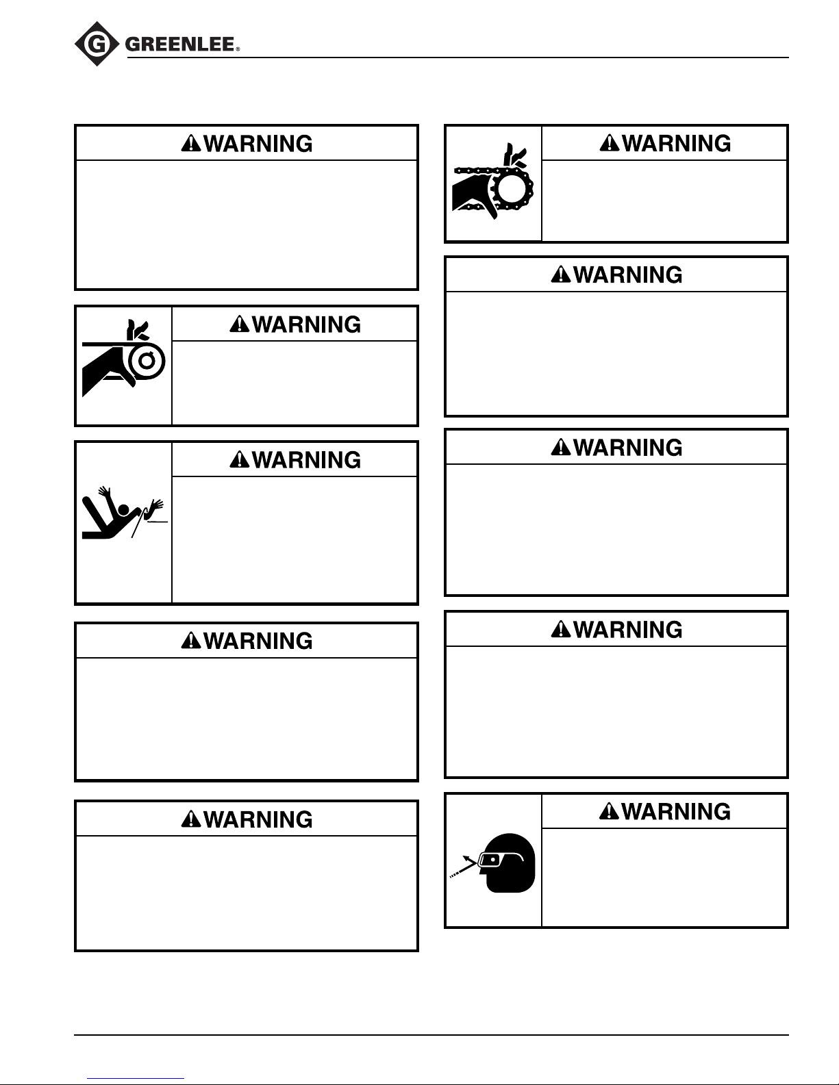
Keep hands away from the capstan.
Rope at the capstan can crush a hand.
Failure to observe this warning could
result in severe injury or death.
Do not wrap rope around hands,
arms, waist or other body parts.
Do not stand in spent coils or tailed
rope. Hold rope so that it may be
released quickly.
Failure to observe this warning could
result in severe injury or death.
Do not operate without chain guards
in place.
Failure to observe this warning could
result in severe injury or death.
Use this tool for manufacturer’s intended purpose
only. Do not use the cable puller as a hoist or winch.
• The cable puller cannot lower a load.
• The load may fall.
Failure to observe this warning could result in severe
injury or death.
Inspect puller and accessories before use. Replace
any worn or damaged components with Greenlee
replacement parts. A damaged or improperly
assembled item can break and strike nearby
personnel with great force.
Failure to observe this warning could result in
severe injury or death.
Rope, cable, or a connecting device can break
under tension, causing the rope to whip violently.
Do not allow any unnecessary personnel to remain
in the area during the pull.
Failure to observe this warning could result in
serious injury or death.
Do not allow the rope to become overlapped on the
capstan. If an overlap begins to develop, relax the
tailing force immediately and shut off the cable
puller.
Failure to observe this warning could result in
severe injury or death.
Greenlee / A Textron Company 5 4455 Boeing Dr. • Rockford, IL 61109-2988 USA • 815-397-7070
Entanglement hazard:
• Do not operate the cable puller while wearing
loose-fitting clothing.
• Retain long hair.
Failure to observe these warnings could result in
severe injury or death.
Wear eye protection when using this
tool.
Failure to wear eye protection could
result in severe eye injury from
flying debris.
Page 6
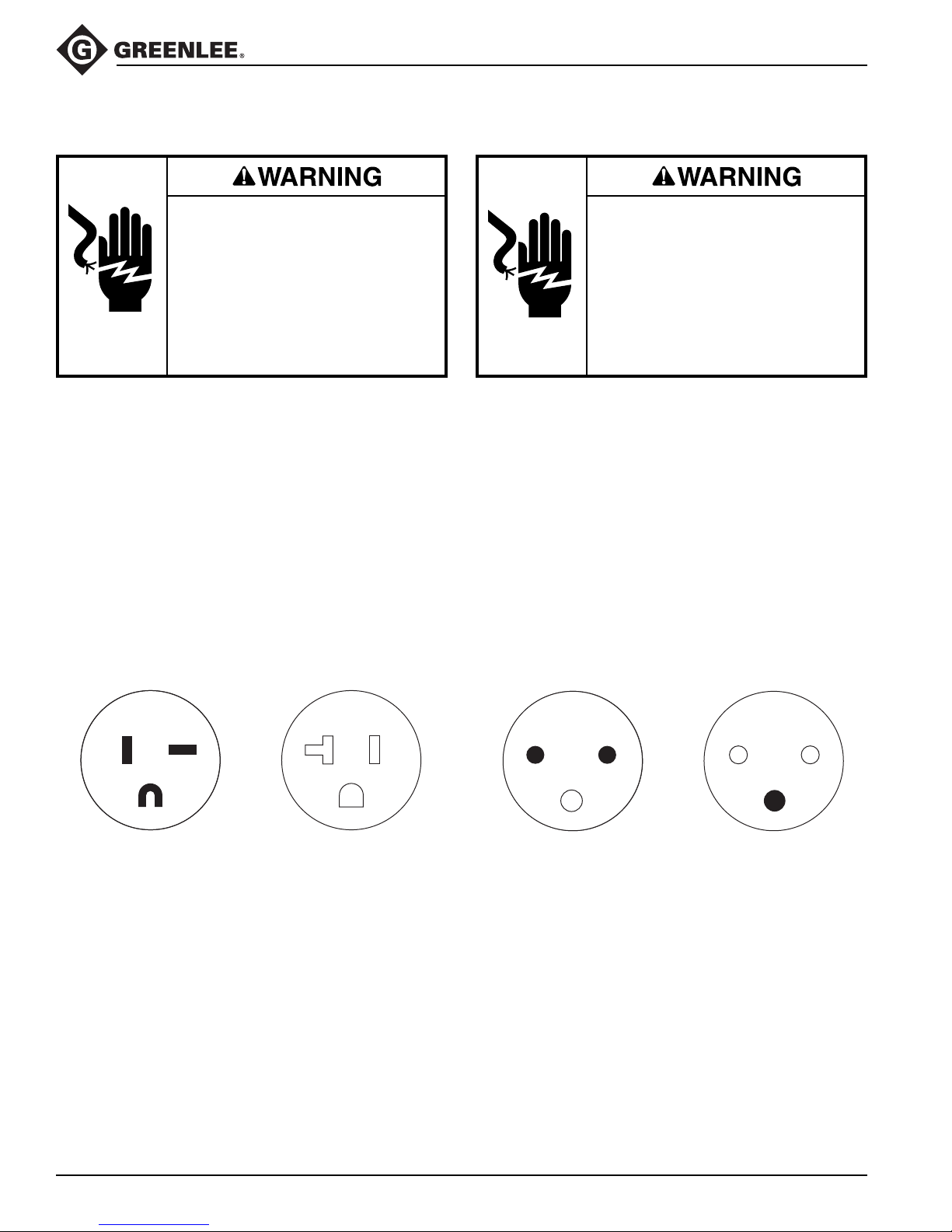
Grounding Instructions
2001-Series Easy Tugger Cable Pullers
120-Volt Model
Electric shock hazard.
• Do not modify the plug provided
with the tool.
• Connect this tool to a grounded
receptacle on a 20-amp GFCIprotected circuit.
Failure to observe these warnings
could result in severe injury or death.
This tool must be grounded. In the event of a malfunction or breakdown, an electrical ground provides a path
of least resistance for the electric current. This path of
least resistance is intended to reduce the risk of electric
shock.
This tool’s electric cord has a grounding conductor
and a grounding plug as shown. Do not modify the
plug. Connect the plug to a corresponding receptacle
that is properly installed and grounded in accordance
with all national and local codes and ordinances.
Do not use an adapter.
220-Volt Model
Electric shock hazard.
• Do not modify the plug provided
with the tool.
• Connect this tool to a grounded
receptacle on a 10-amp GFCIprotected circuit.
Failure to observe these warnings
could result in severe injury or death.
This tool must be grounded. In the event of a malfunction or breakdown, an electrical ground provides a path
of least resistance for the electric current. This path of
least resistance is intended to reduce the risk of electric
shock.
This tool’s electric cord has a grounding conductor
and a grounding plug as shown. Do not modify the
plug. Connect the plug to a corresponding receptacle
that is properly installed and grounded in accordance
with all national and local codes and ordinances.
Do not use an adapter.
20 Amp/125 Volt
Plug and Receptacle
10 Amp/250 Volt
Plug and Receptacle
ReceptaclePlug
ReceptaclePlug
Greenlee / A Textron Company 6 4455 Boeing Dr. • Rockford, IL 61109-2988 USA • 815-397-7070
Page 7
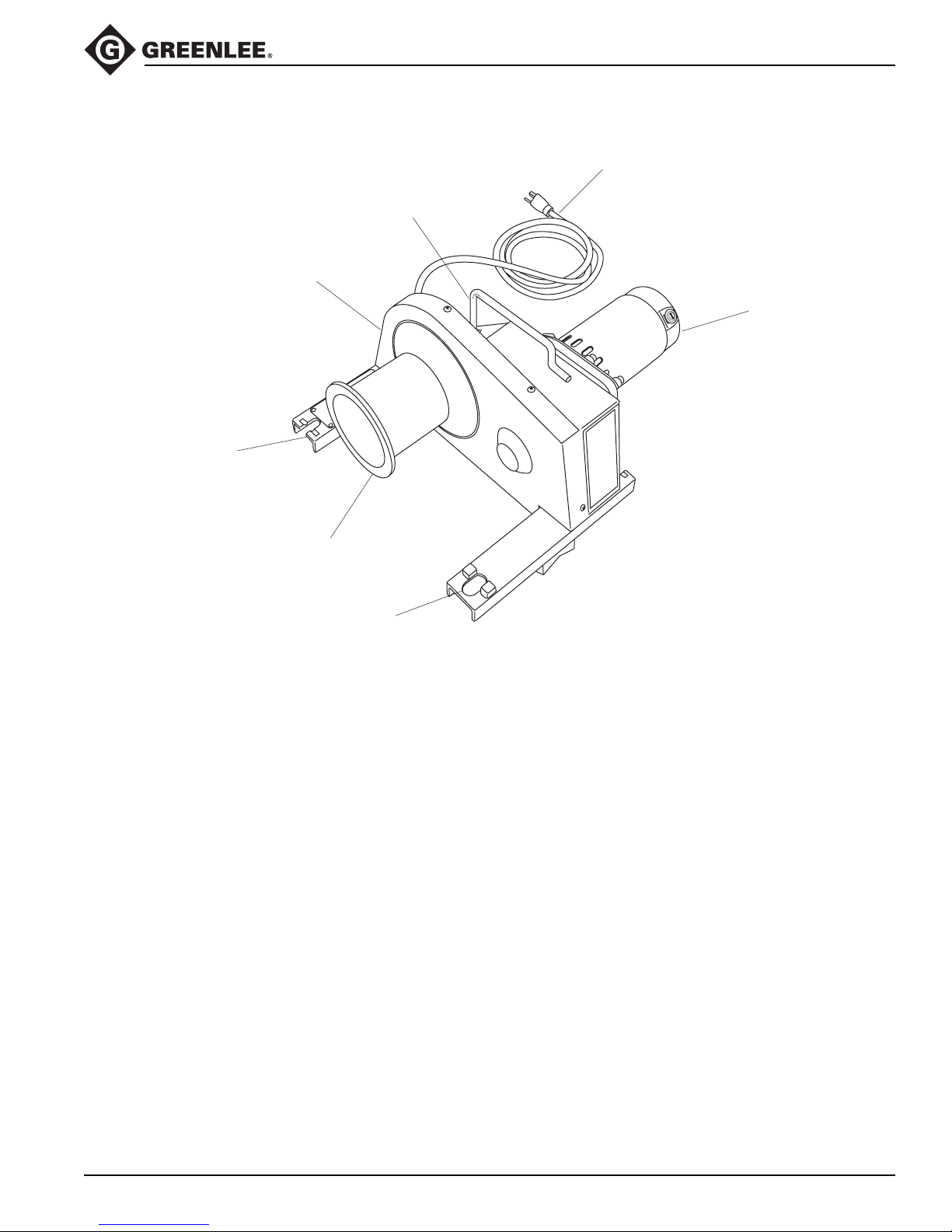
Identification
2001-Series Easy Tugger Cable Pullers
7
2
1
4
5
8
6
Easy Tugger Identification
1. Capstan Chain Guard
2. Handle
3. Guarded ON/OFF Switch
and Circuit Breaker (not shown)
4. Motor
5. Hole for Vise Chain
6. Vise Chain Pocket
7. Power Cord
8. Tapered Capstan
Greenlee / A Textron Company 7 4455 Boeing Dr. • Rockford, IL 61109-2988 USA • 815-397-7070
Page 8

Specifications
Weight ................................................................................................... 19.8 kg (44 lb)
Dimensions:
Length ................................................................................................. 381 mm (15")
Width..................................................................................................... 483 cm (19")
Height ................................................................................................. 241 cm (9.5")
Power (120-Volt Model)
Voltage............................................................................................ 120 VAC, 60 Hz
Current .......................................................................................................... 8 Amps
Source .................................................................... 20 Amp GFCI-Protected Circuit
Power (220-Volt Model):
Voltage............................................................................................ 220 VAC, 50 Hz
Current .......................................................................................................... 4 Amps
Source .................................................................... 10 Amp GFCI-Protected Circuit
Maximum Pulling Force....................................................................8.89 kN (2000 lb )
Speed:
No load .............................................................. 6.7 meters/minute (22 feet/minute)
8.89 kN (2000 lb) ............................................. 3.35 meters/minute (11 feet/minute)
Duty Cycle:
0 - 6.22 kN (0 - 1400 lb) ......................................................... Continuous Operation
6.22 - 8.89 kN (1400 - 2000 lb) ................................. 10 minutes on / 10 minutes off
Pulling Rope:
Average Breaking Strength............................................ 35.6 kN (8000 lb) minimum
2001-Series Easy Tugger Cable Pullers
:
Greenlee / A Textron Company 8 4455 Boeing Dr. • Rockford, IL 61109-2988 USA • 815-397-7070
Page 9

Cable Pulling Glossary
2001-Series Easy Tugger Cable Pullers
anchoring system
any item or group of items that keeps a cable pulling
component in place during the cable pull
capstan
the hollow cylinder of the cable puller that acts on the
pulling rope to generate pulling force
coefficient of friction
the ratio that compares two amounts of force:
(1) the force needed to move an object over a surface
and (2) the force holding the object against the surface
This ratio is used to describe how the capstan and the
rope work together.
connector
any item, such as a wire grip, clevis, swivel, or pulling
grip, that connects the rope to the cable
direct line of pull
the areas next to the pulling rope and along its path;
this includes the areas in front of, in back of, and underneath the rope
maximum rated capacity
the amount of pulling tension that any component
can safely withstand, rated in kilo-Newtons (metric)
or pounds; the maximum rated capacity of every
component must meet or exceed the maximum pulling
force of the cable puller
Newton
a metric unit of force, equivalent to .225 pounds of force
pipe adapter sheave
attaches to conduit for pulling or feeding cable
pulling grip
pulling force
the amount of pulling tension developed by the cable
puller, rated in Newtons (metric) or pounds; a cable
puller is usually described by the maximum pulling force
that it can develop
resultant force
any force that is produced when two or more forces act
on an object; applies to the sheaves of a cable pulling
system
sheave
a pulley that changes the direction of the rope and cable
stored energy
the energy that accumulates in the pulling rope as it
stretches, described in Newtons-meters (metric) or
foot-pounds
support structure
any stationary object that a cable pulling system
component is anchored to, such as a concrete floor
(for the floor mount) or an I-beam (for a sheave)
tail
the portion of the rope that the operator applies force to;
this is the rope coming off of the capstan, and is not
under the tension of the pull
tailing the rope
the operator’s main function; this is the process of
applying force to the tail of the pulling rope—see the
complete explanation under Principles of Cable Pulling
wire grip
connects the rope to the cable; some use a set screw to
clamp onto the conductors of the cable
connects the rope to the cable; consists of a wire mesh
basket that slides over the cable and grips the insulation
Greenlee / A Textron Company 9 4455 Boeing Dr. • Rockford, IL 61109-2988 USA • 815-397-7070
Page 10
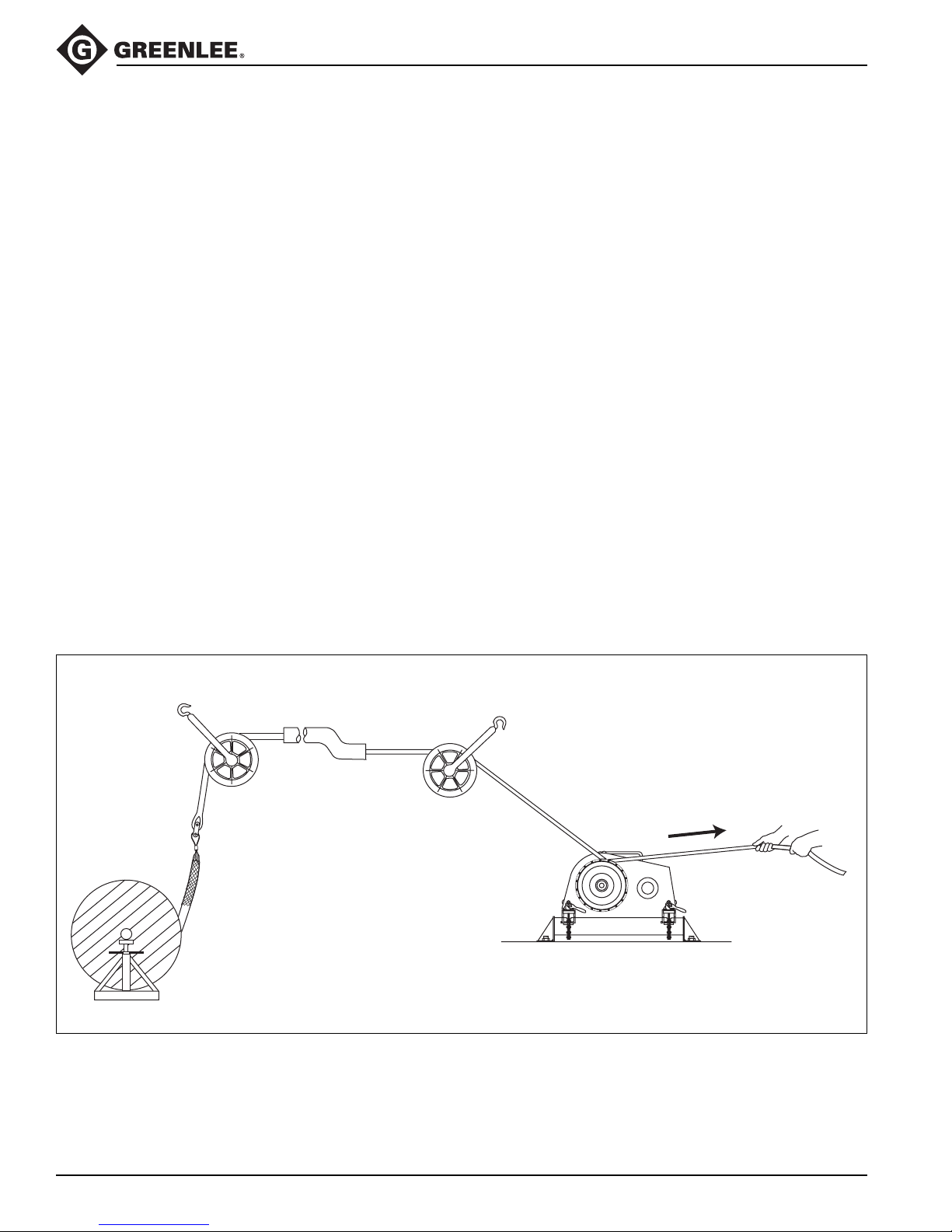
Cable Pulling Principles
2001-Series Easy Tugger Cable Pullers
Pulling cable is a complex process. This section of
the manual describes and explains four main topics
of pulling cable:
• each cable pulling system component
• how these components work together
• forces that are generated
• procedures for the cable puller operator to follow
While reading through this section of the manual, look
for components that are shaded in the illustrations. The
shading indicates components that are associated with
the text.
Greenlee strongly recommends that each member of the
cable pulling crew review this section of the manual
before each cable pull.
Cable Pulling Systems
Pulling cable requires a system of components. At a
minimum, a cable pulling system will include a cable
puller, a cable pulling rope, and connectors to join the
rope to the cable. Most systems will also include, but are
not limited to, a cable puller anchoring system, pulling
sheaves and sheave anchoring systems.
The cable puller has a maximum amount of pulling force,
which is the amount of pulling tension that it develops.
Every other component of the pulling system has a
maximum rated capacity, which is the amount of pulling
tension that it can withstand. The maximum rated
capacity of every component must meet or exceed the
cable puller’s maximum pulling force.
Typical Cable Pulling System
Tailing
Force
Greenlee / A Textron Company 10 4455 Boeing Dr. • Rockford, IL 61109-2988 USA • 815-397-7070
Page 11
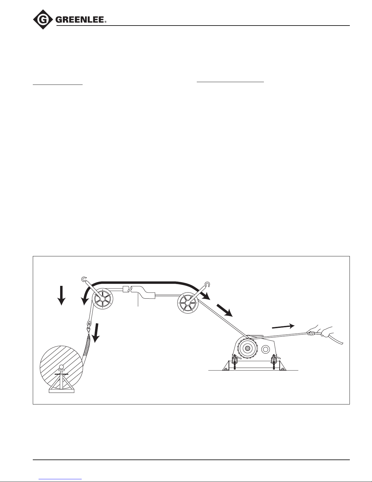
Cable Pulling Principles (cont’d)
2001-Series Easy Tugger Cable Pullers
Pulling Theory
This section introduces the main ideas involved with
pulling cable.
Pulling Resistance
The cable puller must overcome two types of resistance:
gravity and friction.
Gravity constantly exerts its force on the vertical
portions of the run. When the pulling force is relaxed,
gravity attempts to pull the cable downward. Friction
develops where the cable contacts the sheaves, conduit
and tray. Friction resists any movement, forward or
backward, and tends to hold the cables in place.
To accomplish a cable pull, the cable pulling system
must develop more force than the combination of gravity
and friction.
Generating Pulling Force
To generate pulling force, the capstan works as a
force
multiplier
. The operator exerts a small amount
of force on the rope. The cable puller multiplies this
and generates the pulling force.
This pulling force is applied to the rope, connectors,
and cable in order to accomplish the pull. The direction
of force is changed, where necessary, with pulling
sheaves.
Gravity
Weight
of Cable
Cable Pulling Theory Illustrated
Friction
Conduit
Pulling Force
8.89 kN
(2000 lb)
Tailing
Force
Greenlee / A Textron Company 11 4455 Boeing Dr. • Rockford, IL 61109-2988 USA • 815-397-7070
Page 12
Cable Pulling Principles (cont’d)
2001-Series Easy Tugger Cable Pullers
Cable Pulling Forces
This section provides detailed explanations and illustrations of the forces that are generated during the cable
pull. These explanations are based on the concepts
presented in the previous section, Pulling Theory.
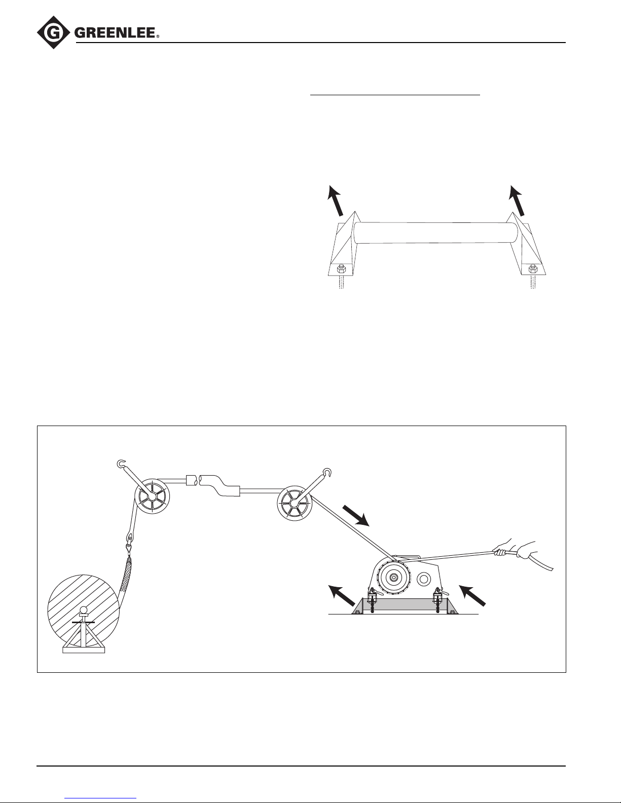
At the Cable Puller Anchoring System
The cable puller will exert its maximum pulling force on
cable puller’s anchoring system. It is extremely important
the anchoring system can withstand this amount of
force. See the instruction manual provided with your
anchoring system for proper setup or installation.
Pulling Force at the Cable Puller’s Anchoring System
Pulling Force
8.89 kN
(2000 lb)
8.89 kN
(2000 lb)
Maximum
Maximum Pulling Force
at Anchoring System
8.89 kN
(2000 lb)
Maximum
Greenlee / A Textron Company 12 4455 Boeing Dr. • Rockford, IL 61109-2988 USA • 815-397-7070
Page 13
Cable Pulling Principles (cont’d)
2001-Series Easy Tugger Cable Pullers
Cable Pulling Forces (cont’d)
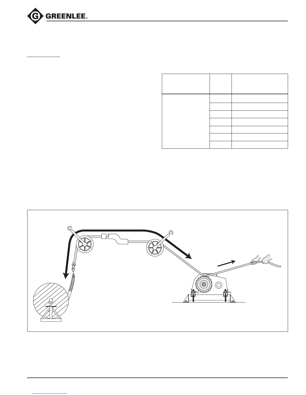
At the Capstan
The capstan acts as a
force multiplier
. The operator
exerts a small amount of tension, or tailing force, on the
rope; the capstan multiplies this force to pull the cable.
The resultant force depends upon the number of times
the rope is wrapped around the capstan, as shown in the
formula below.
Pulling Force = Tailing Force x e
0.0175µø
Where: e = the natural logarithm, or 2.7183
µ = the coefficient of friction between the
rope and the capstan *
ø = the number of degrees of wrap of rope
around the capstan
* The average value for the coefficient of friction when
double-braided composite rope is pulled over a clean
dry capstan is 0.125.
The following table is based on the formula above.
The input, or tailing force, is constant at 44.5 Newtons
(10 lb). Increasing the number of wraps increases
the pulling force.
Number
Operator’s of Wraps Approximate
Tailing Force of Rope Pulling Force
1 93.4 N (21 lb)
2 213.5 N (48 lb)
44.5 N (10 lb) 3 474.9 N (106 lb)
4 1043.8 N (233 lb)
5 2293.7 N (512 lb)
6 5048.9 N (1127 lb)
7 11.1 kN (2478 lb)
This table shows how the capstan acts as a force
multiplier. Because the coefficient of friction depends
upon the condition of the rope and capstan, this formula
cannot determine an exact amount of pulling force.
The Capstan as a Force Multiplier
Pulling Force: 8.89 kN (2000 lb)
Tailing
Force
Greenlee / A Textron Company 13 4455 Boeing Dr. • Rockford, IL 61109-2988 USA • 815-397-7070
Page 14
Cable Pulling Principles (cont’d)
2001-Series Easy Tugger Cable Pullers
Cable Pulling Forces (cont’d)
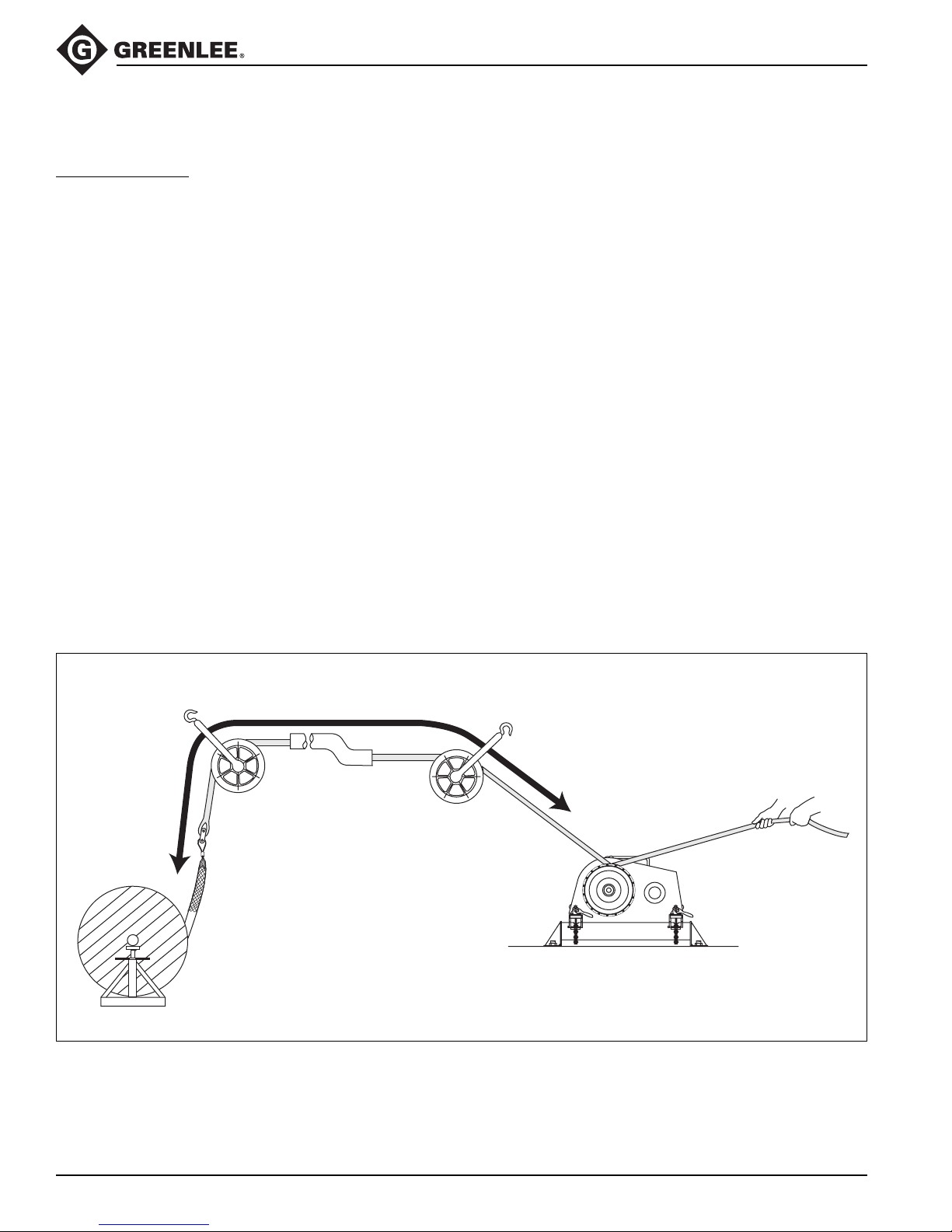
At the Pulling Rope
The product of a force (f) moving through a distance (d)
is energy (f x d), and may be measured in Newtonmeters or foot-pounds. Energy is stored in a rope when
the rope is stretched. This is similar to the way energy is
stored in a rubber band when it is stretched. Failure of
the rope or any other component of the pulling system
can cause a sudden uncontrolled release of the energy
stored in the rope.
For example, a 100-meter nylon rope with a 50,000
Newton average breaking strength could stretch 40
meters and store 1,000,000 joules of energy. This is
enough energy to throw a 900-kilogram object, such as
a small automobile, 113 meters into the air.
A similar double-braided composite rope could store
approximately 300,000 joules of energy. This could
throw the same object only 34 meters into the air.
The double-braided composite rope stores much less
energy and has much less potential for injury if it were to
break.
Multiplex polyester rope is the only type of rope recommended for use with the Easy Tugger cable puller.
Select a multiplex polyester rope with an average-rated
breaking strength of at least 35.6 kN (8000 lb).
Stored Energy
Stored Energy
Greenlee / A Textron Company 14 4455 Boeing Dr. • Rockford, IL 61109-2988 USA • 815-397-7070
Page 15
Cable Pulling Principles (cont’d)
2001-Series Easy Tugger Cable Pullers
Cable Pulling Forces (cont’d)
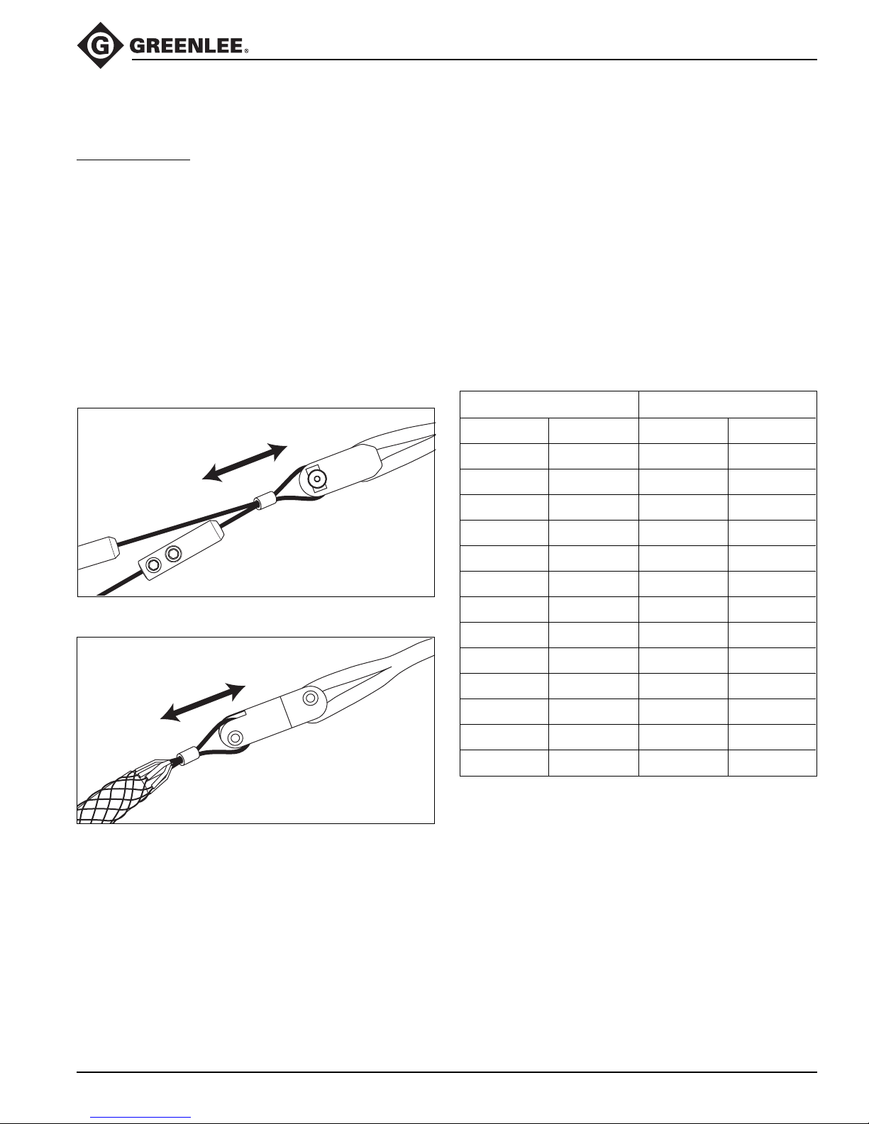
At the Connectors
The connectors will be subjected to the cable puller’s
maximum pulling force.
Several types of rope connectors—clevises, swivels,
and rope-to-swivel connectors—are available. Follow
the instructions provided with each to provide a good
connection.
Two types of wire connectors—wire grips and pulling
grips—are available. The wire grip uses a set screw
to clamp onto the conductors of the cable. The pulling
grip consists of a wire mesh basket that slides over
the cable and grips the insulation.
A Typical Grip Setup—Clevis and Wire Grip
Maximum
Pulling Force
8.89 kN
(2000 lb)
When selecting a pulling grip, it is extremely important to
select a grip of the correct (1) type, (2) size, and (3)
maximum rated capacity.
1. Select the correct type based on the descriptions
of each type in the Greenlee catalog.
2. Measure the circumference of the wire bundle.
(To do this accurately, fasten a tie strap around the
bundle. Cut off and discard the tail. Then cut the
tie strap and measure its length.) Use the table
provided to find the correct size.
3. See the maximum rated capacities in the Greenlee
catalog.
Pulling Grip Size Table
Circumference Range Required Grip Diameter
inches mm inches mm
1.57 - 1.95 39.9 - 49.5 0.50 - 0.61 12.7 - 15.5
1.95 - 2.36 49.5 - 59.9 0.62 - 0.74 15.8 - 18.8
2.36 - 3.14 59.9 - 79.8 0.75 - 0.99 19.1 - 25.1
3.14 - 3.93 79.8 - 99.8 1.00 - 1.24 25.4 - 31.5
A Typical Grip Setup—Swivel and Pulling Grip
Maximum
Pulling Force
8.89 kN
(2000 lb)
3.93 - 4.71 99.8 - 119.6 1.25 - 1.49 31.8 - 37.8
4.71 - 5.50 119.6 - 139.7 1.50 - 1.74 38.1 - 44.2
5.50 - 6.28 139.7 - 159.5 1.75 - 1.99 44.5 - 50.5
6.28 - 7.85 159.5 - 199.4 2.00 - 2.49 50.8 - 63.2
7.85 - 9.42 199.4 - 239.3 2.50 - 2.99 63.5 - 75.9
9.42 - 11.00 239.3 - 279.4 3.00 - 3.49 76.2 - 88.6
11.00 - 12.57 279.4 - 319.3 3.50 - 3.99 88.9 - 101.3
12.57 - 14.14 319.3 - 359.2 4.00 - 4.49 101.6 - 114.0
14.14 - 15.71 359.2 - 399.0 4.50 - 4.99 114.3 - 126.7
Greenlee / A Textron Company 15 4455 Boeing Dr. • Rockford, IL 61109-2988 USA • 815-397-7070
Page 16
Cable Pulling Principles (cont’d)
2001-Series Easy Tugger Cable Pullers
Cable Pulling Forces (cont’d)
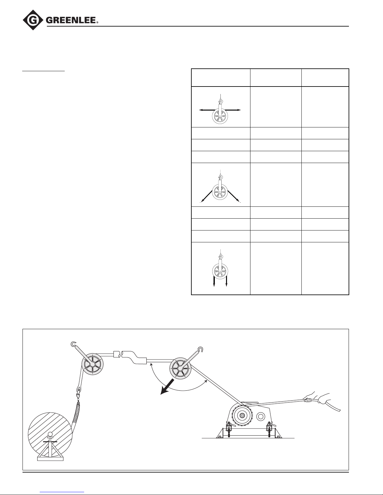
At the Sheaves
Sheaves are used to change the direction of the pull.
A change in direction creates a new
is
greater than
This new resultant force exerts itself on the sheaves,
sheave anchoring system, and support structures
illustrated.
The resultant amount of force depends on the angle of
the change in direction. A brief table is provided here;
for more details, see IM 1363 (99929988).
the cable puller’s maximum pulling force.
resultant force
that
Resultant Force Table for the Easy Tugger
(8.89 kN or 2000 lb Maximum Pulling Force)
Illustration
Angle of Change
in Direction
180° 0 (0)
150° 4.63 (1040)
135° 6.85 (1540)
120° 8.89 (2000)
90° 12.5 (2820)
60° 15.4 (3460)
45° 16.5 (3700)
Resultant Force
kN (lb)
Typical Resultant Force at Sheave
135
Resultant Force=
6.85 kN (1540 lb)
30° 17.2 (3860)
0° 17.8 (4000)
Greenlee / A Textron Company 16 4455 Boeing Dr. • Rockford, IL 61109-2988 USA • 815-397-7070
Page 17
Cable Pulling Principles (cont’d)
2001-Series Easy Tugger Cable Pullers
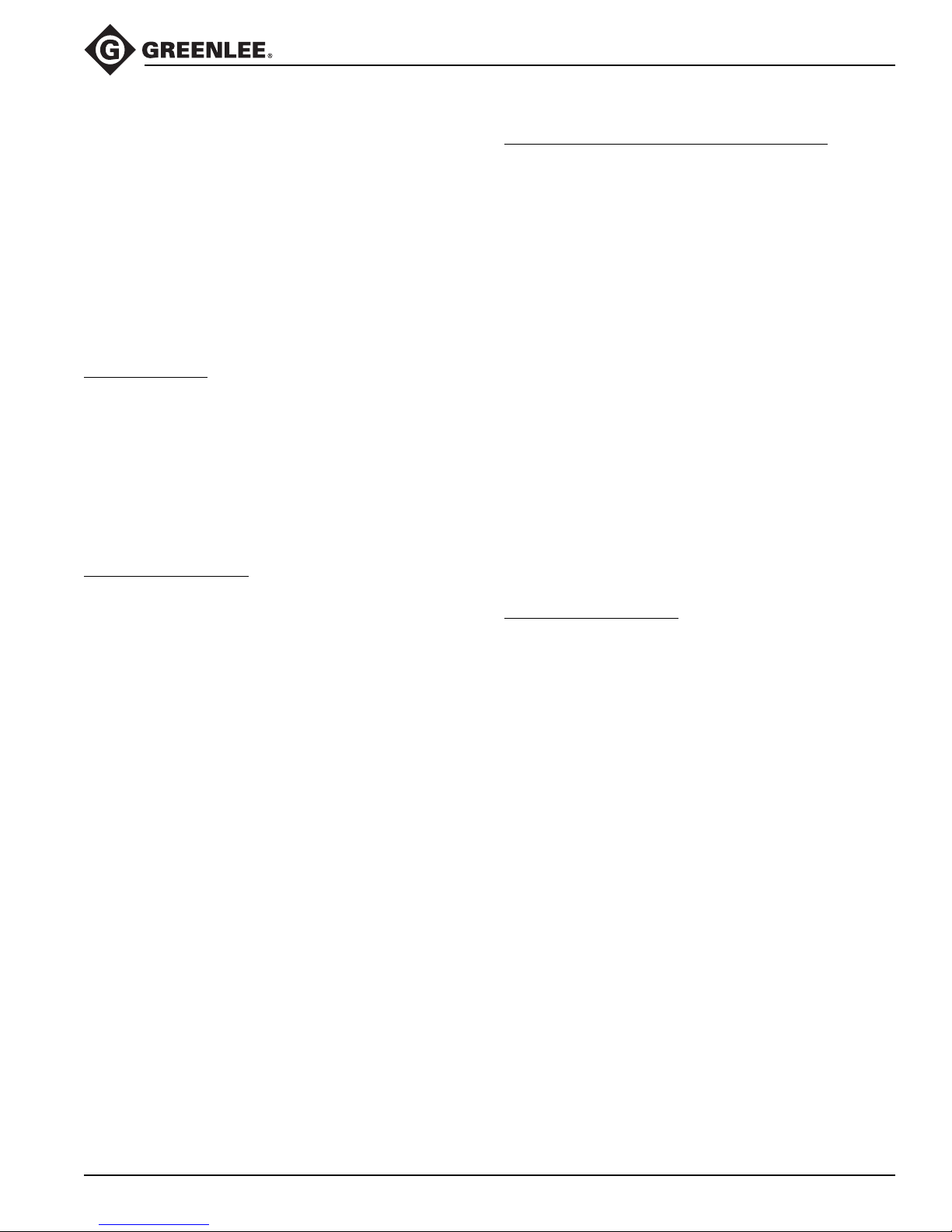
Tailing the Rope
The rope must be pulled off of the capstan as the pull
progresses. The rope that has left the capstan is the
“tail.” The process of pulling the rope off of the capstan
is called
The resistance of the cable varies throughout the
duration of the cable pull. Changes in resistance are
due to characteristics of the rope, changes in conduit
direction, and changes in the amount of friction. The
“feel” of the rope provides this information about the pull.
This is called
necessary to compensate for these changes.
Control of the Pull
Decreasing the tailing force will decrease the pulling
force, until the rope slips on the capstan and the pull
stops. This provides a high level of control over the
progress of the cable pull.
Do not allow the rope to slip on the capstan for more
than a few moments. If it becomes necessary to completely stop a pull, shut off the puller and maintain
enough tailing force to hold cable in place. Tie the rope
off to hold it in place.
Amount of Tailing Force
While the rope and cable are under tension, it is impor-
tant to maintain the proper amount of tailing force.
Too
capstan. This will build up excessive heat and accelerate
rope wear, increasing the possibility of breaking the
rope.
The proper amount of tailing force will stop the rope from
slipping on the capstan and produce a sufficient amount
of pulling force to pull in the rope and cable.
Too much
necessary to stop the rope from slipping on the capstan.
Excessive tailing force will not increase the pulling force
or pulling speed.
tailing the rope
tactile feedback
little
tailing force will allow the rope to slip on the
tailing force is any amount more than is
.
. Adjust the tailing force as
Number of Wraps of Rope Around the Capstan
An experienced operator should choose the number of
times the rope is wrapped around the capstan.
The proper number of wraps allows the operator to
control the progress of the pull with a comfortable
amount of effort.
Using
too few
accomplish the pull. Using too few wraps also makes the
rope more likely to slip on the capstan. This builds up
heat and accelerates rope wear.
Using
too many
capstan more tightly. This accelerates rope wear,
wastes power, and increases the possibility of a rope
overlap. Using too many wraps also reduces tactile
feedback, so you receive less information about the pull.
You cannot quickly relax the tailing force when there are
too many wraps.
If the rope becomes difficult to tail, add another wrap of
rope. Turn off the puller and release all of the tension in
the rope. Add a wrap and resume pulling. Be aware,
however, that some pulls will require tension to hold the
cables in place. In these cases, do not attempt to
release all of the tension and add a wrap of rope. You
will need to anticipate the number of wraps before
starting the pull.
Preventing Rope Overlap
Do not allow the rope to become overlapped on the
capstan during a pull.
A rope overlap will make it impossible to continue or
back out of the pull.
If the rope becomes overlapped, you will lose control of
the pull—the rope will advance with no tailing force and
will not feed off of the capstan. The capstan will not allow
you to reverse the direction of the rope, so you cannot
back out of an overlap.
Set up the puller properly. The positioning peg, entrapment peg, rope ramp and tapered capstan are intended
to prevent rope overlap. See the instructions in the
Operation section of this manual.
Every wrap of the rope must remain in direct contact with
the capstan. During the pull, take great care to prevent
the incoming rope from riding up and overlapping the
next wrap. If an overlap begins to develop, immediately
relax the tailing force on the rope so that the rope can
feed back toward the conduit or tray. When the rope
resumes its normal path, apply tailing force and continue
the pull.
There is no suggested remedy for a rope overlap.
Do not allow the rope to overlap!
wraps requires a large tailing force to
wraps causes the rope to grab the
Greenlee / A Textron Company 17 4455 Boeing Dr. • Rockford, IL 61109-2988 USA • 815-397-7070
Page 18

2001-Series Easy Tugger Cable Pullers
Cable Pulling Principles (cont’d)
Summary of Cable Pulling Principles
• A cable pulling system consists of many components
that work together to accomplish a pull.
• The cable puller is rated by its maximum pulling
force; every other component is rated by its maximum
rated capacity. The maximum rated capacity of every
component must meet or exceed the maximum pulling
force of the cable puller.
• The cable puller must overcome two types of resistance: gravity and friction. The puller’s capstan, the
pulling rope, and the operator tailing the rope work
together to produce pulling force.
• The cable puller exerts force on every component of
the cable pulling system, including the anchoring
systems and the support structures.
• Energy is stored in a rope when the load causes
the rope to stretch. Failure of the rope or any other
component can cause a sudden release of energy.
Replace any rope that is worn or damaged.
• Carefully select the number or wraps of rope around
the capstan before starting the pull.
• Control the pull by tailing the rope. Be familiar with the
interaction of the rope and capstan.
• Do not allow a rope overlap to develop.
Planning the Pull
• Pull in a direction that will require the lowest amount of
pulling force.
• Plan several shorter pulls rather than fewer longer
pulls.
• Locate the puller as close to the end of the conduit as
possible to minimize the amount of exposed rope
under tension.
• Place each component so that the pulling forces are
used effectively.
• Select an anchoring system: adapter sheaves, which
are preferred, or the floor mount.
• Verify that each component has the proper load rating.
• Inspect the structural supports. Verify that they have
enough strength to withstand the maximum forces that
may be generated.
Greenlee / A Textron Company 18 4455 Boeing Dr. • Rockford, IL 61109-2988 USA • 815-397-7070
Page 19
2001-Series Easy Tugger Cable Pullers
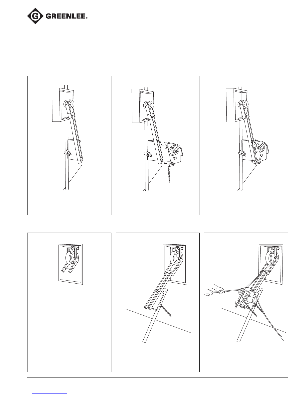
Typical Setups
Setups are shown without force gauge. Place the force gauge so the operator has an unobstructed view of
the meter and quick access to its ON/OFF switch.
Using a Pipe Adapter Sheave to Pull through Exposed Conduit
Attach 2049 Pipe Adapter Sheave to
conduit with chain.
Using an Extension Bushing, Flexible Pipe Adapter and Adapter Sheave to Pull through Concealed Conduit
Position 2001 Puller onto 2049 with leg
under locking tab. Secure 2001 Puller to 2049 with chains.
Attach 685 Flexible Pipe Adapter
to Bushing.
Greenlee / A Textron Company 19 4455 Boeing Dr. • Rockford, IL 61109-2988 USA • 815-397-7070
Attach 2049 Pipe Adapter Sheave to 685
with pin and clips.
Secure 2001 Puller to 2049 with chains.
Page 20
2001-Series Easy Tugger Cable Pullers
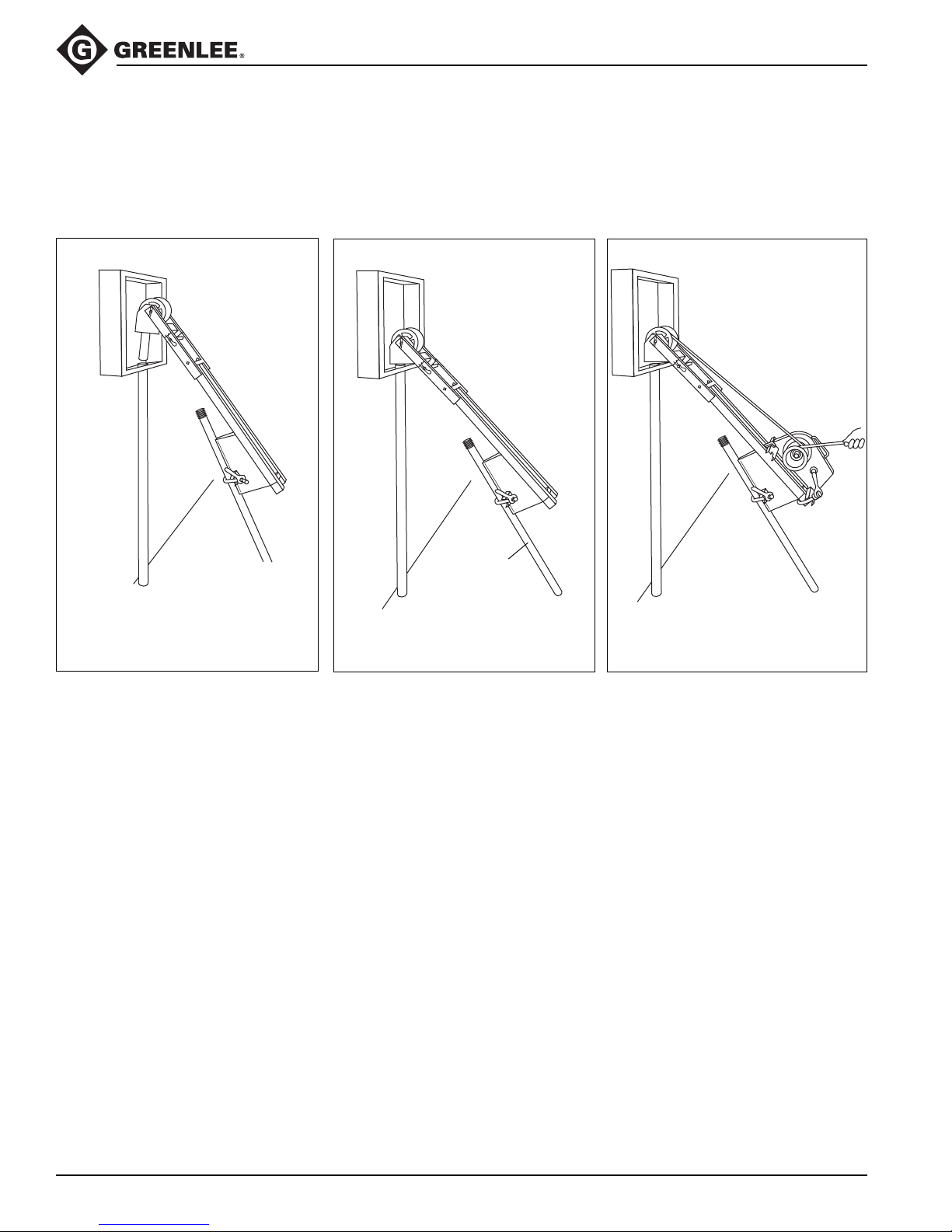
Typical Setups (cont’d)
Setups are shown without force gauge. Place the force gauge so the operator has an unobstructed view of
the meter and quick access to its ON/OFF switch.
Using a Feeding Sheave and Pipe Adapter
Insert 441 Feeding Sheave with 2049
Pipe Adapter Sheave into conduit.
Conduit
for support
Secure 2001 Puller to 2049 with chains.
Greenlee / A Textron Company 20 4455 Boeing Dr. • Rockford, IL 61109-2988 USA • 815-397-7070
Page 21
2001-Series Easy Tugger Cable Pullers
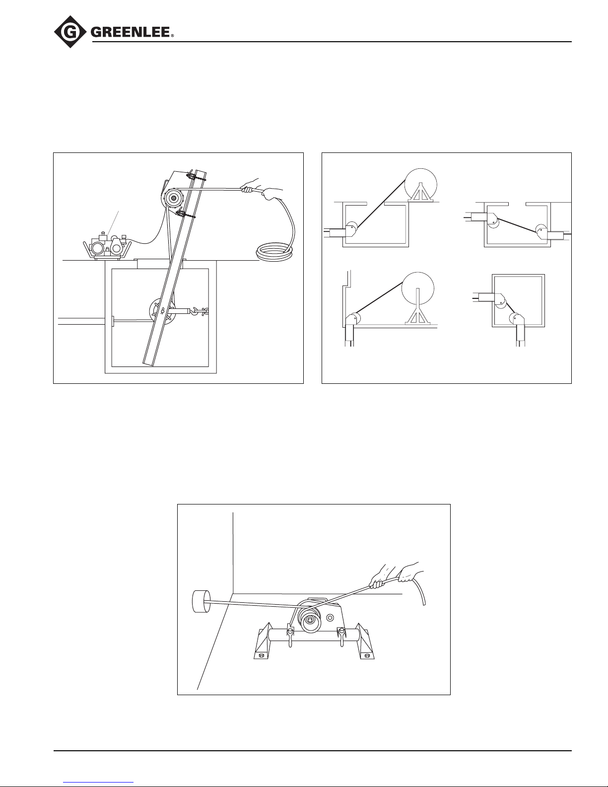
Typical Setups (cont’d)
Setups are shown without force gauge. Place the force gauge so the operator has an unobstructed view
of the meter and quick access to its ON/OFF switch.
Using a Manhole Sheave Using Feeding Sheaves in Manholes
Generator
UNOCCUPIED MANHOLE UNOCCUPIED MANHOLE
Using a Floor Mount
UNOCCUPIED MANHOLEABOVE GROUND
Greenlee / A Textron Company 21 4455 Boeing Dr. • Rockford, IL 61109-2988 USA • 815-397-7070
Page 22
2001-Series Easy Tugger Cable Pullers
Setup and Operation
While reading through this section of the manual, look
for components that are shaded in the illustrations. The
shading indicates components that are associated with
the accompanying text.
1. Fish the rope through the conduit.
2. Set up the cable puller mounting. Set it up so that
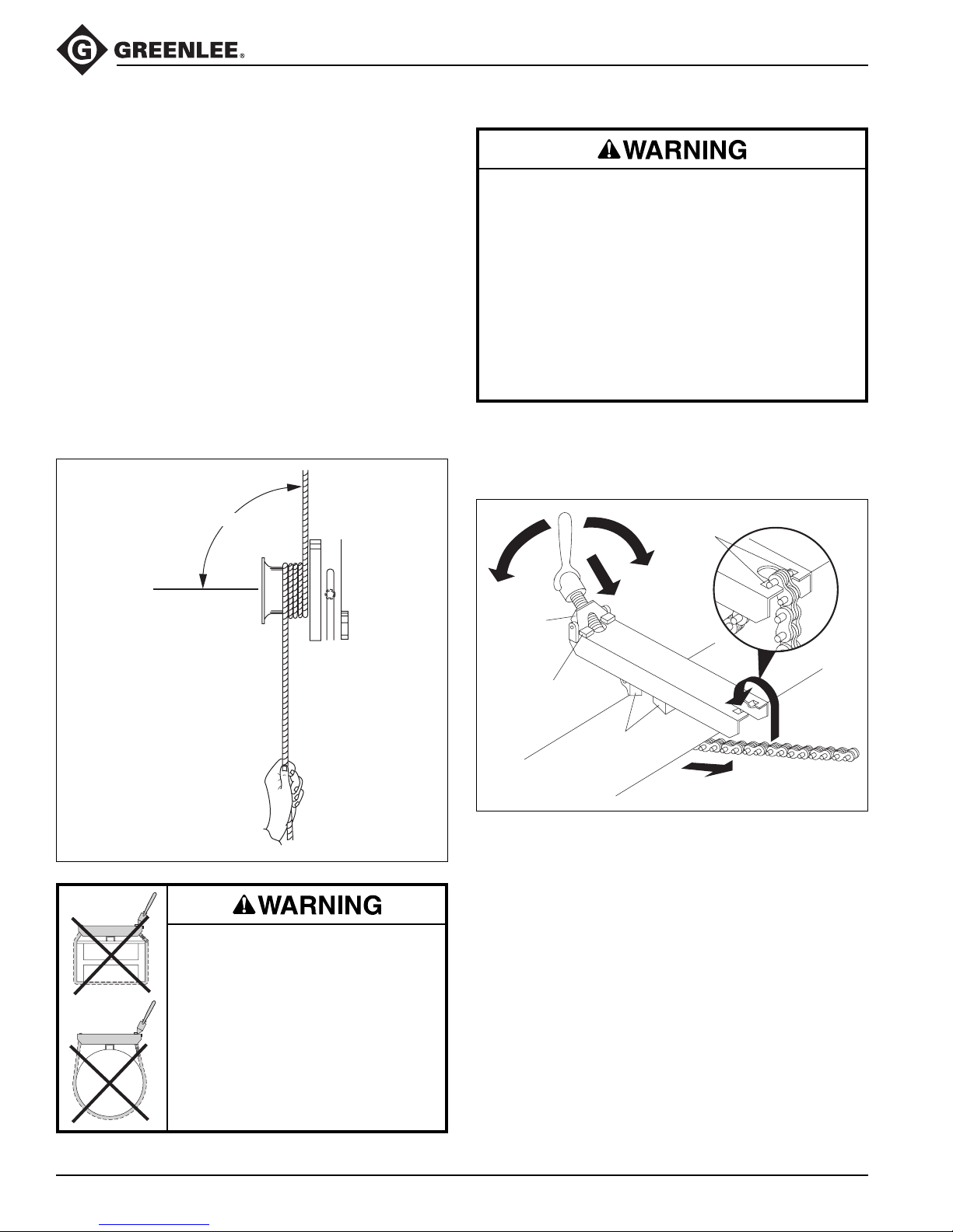
the rope will approach the capstan at an angle of
90° (±5°) as illustrated in Rope Approaching the
Capstan.
Note: If using an adapter sheave, flexible pipe
adapter, or mobile T-boom, see the illustrations in
this manual. If using a manhole sheave or floor
mount, see the instructions supplied with those
items.
Install the vise chains properly.
• Follow the vise chain tightening instructions
carefully. Improperly tightened chains can allow
the puller to slide or break loose and strike nearby
personnel.
• Do not allow the vise chains to bind at the corners
when mounting the puller to a square or rectangular support. The vise chain must be uniformly tight
at all points.
Failure to observe this warning could result in severe
injury or death.
Rope Approaching the Capstan
90°
NO
When setting up the flexible pipe
adapter or puller, do not use the vise
chains on a structural support that
is less than 51 mm (2") or more than
NO
254 mm (10") wide. An oversized
or undersized structural support
can allow the puller to slide or break
loose and strike nearby personnel
with sufficient force to cause severe
injury or death.
3. Install the vise chains as shown.
Vise Chain Installation
Chain
Pockets
D
E
Positioner
Positioning
Block
A
B
Gripping
Feet
C
a. Rotate the vise chain handle to expose most of
the threads. Leave only three or four threads
engaged in the handle.
b. Thread the chain though the hole in the frame.
Set the positioner against the positioning blocks.
c. Wrap the chain around the conduit, pipe sheave
adapter, or structural element.
d. Pull the vise chain tight and insert the chain pins
into the chain pockets, or recesses.
e. Turn the handle to slightly tighten the chain.
f. Repeat Steps A - E for the other chain.
4. Rotate the vise chain handles, by hand, clockwise to
fully tighten the chain. Do not use tools, extensions
or “cheaters.”
Greenlee / A Textron Company 22 4455 Boeing Dr. • Rockford, IL 61109-2988 USA • 815-397-7070
Page 23
2001-Series Easy Tugger Cable Pullers
Setup and Operation (cont’d)
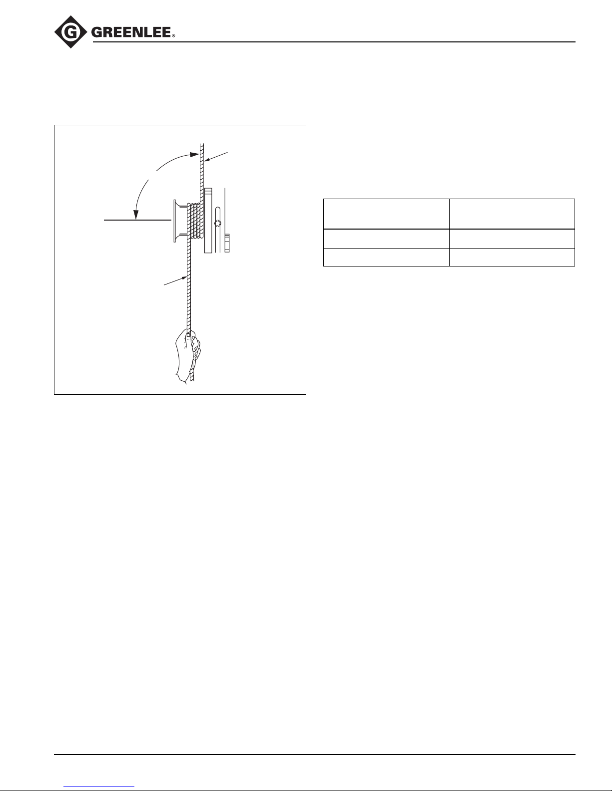
5. Route the rope as illustrated in Rope Path. 6. Check the ON/OFF switch on the puller to be sure
it is OFF. Plug the puller into an appropriate power
Rope Path
PULL
FORCE
ROPE
90°
supply (see Grounding Instructions in this manual).
Note: If using an extension cord, it must be rated for
20 amps. Use the shortest cord possible. Longer
cords reduce puller speed.
Duty Cycle Table
Pounds of Duty Cycle
Pulling Force (in minutes)
0-1400 continuous
1400 - 2000 5 on / 10 off
TAILING
OPERATOR
END
7. Grasp the tailing end of the rope. Apply a slight
amount of tailing force.
8. Turn the puller ON.
9. Tail the rope, allowing the spent rope to accumulate
on the floor between the operator and the puller.
10. When the pull is complete, turn the puller OFF.
Tie off the rope and anchor the cable.
Greenlee / A Textron Company 23 4455 Boeing Dr. • Rockford, IL 61109-2988 USA • 815-397-7070
Page 24

Removing Cable
2001-Series Easy Tugger Cable Pullers
Removing old cable involves the same principles as
installing new cable. However, there are some important
differences.
Pulling Force
It is difficult to predict the amount of pulling force necessary to remove an old cable. The cable may be damaged, and it may break with an unexpectedly low pulling
force.
The required pulling forces may be very high:
• The cable has probably “taken a set.” Unlike the new
cable on a reel, cable in conduit has probably been in
the conduit for years, or perhaps decades. The cable
will resist bending and straightening as it is pulled
through the conduit.
•
The pulling lubricant has probably hardened, increasing
pulling resistance.
• The insulation may be damaged and the cable may be
corroded.
• Dirt or other foreign matter may have entered the
conduit and may have cemented the cable in place.
Puller Placement
Pulling out old cable is generally accomplished with the
puller located some distance away from the end of the
conduit. This allows the pulling crew to pull out a long
section of cable before turning off the puller, cutting off
the cable, and reattaching the grip(s). Mounting the
cable puller a distance away from the end of the conduit
increases the amount of exposed rope, which greatly
increases the amount of violent whipping action which
would occur if the rope or other components were
to break.
To isolate the operator from the rope path:
• Locate the puller so that you will stand behind an
obstruction, such as a wall. Set up the puller so that
you will be able to maintain control of the pull. You
need a clear view of the rope as it feeds onto the
capstan, including several feet of the rope in front of
the capstan. You must be able to turn off the puller
before the pulling grip, connector, or swivel contacts
the capstan.
• Use an additional pulling sheave to change the
direction of the tailing rope. Anchor the sheaveso that
you are close enough to maintain control of the pull.
You need a clear view of the rope as it feeds onto the
capstan, including several feet of the rope in front of
the capstan. You must be able to turn off the puller
before the pulling grip, connector, or swivel contacts
the capstan.
Note: Use the additional pulling sheave to change the
direction of the tailing rope (after the rope leaves the
capstan). Do not change the direction of the pulling
rope.
• Use a longer tailing rope than usual and stand
away from the puller. Stand as far from the puller as
possible, while maintaining control of the pull. You
need a clear view of the rope as it feeds onto the
capstan, including several feet of the rope in front of
the capstan. You must be able to turn off the puller
before the pulling grip, connector, or swivel contacts
the capstan.
Greenlee / A Textron Company 24 4455 Boeing Dr. • Rockford, IL 61109-2988 USA • 815-397-7070
Page 25
Dual Pulling
2001-Series Easy Tugger Cable Pullers
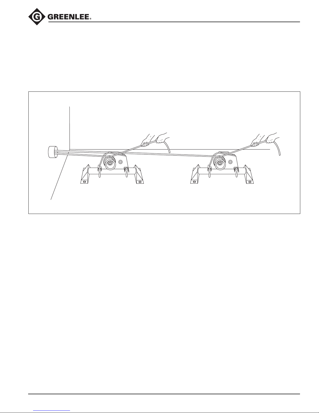
When the estimated amount of pulling resistance exceeds the ability of the puller,
two pullers may be used to accomplish the pull. Connect the two pullers to the
cables in parallel—use two sets of ropes, grips, and other accessories
to avoid overloading any component of the pulling system.
Dual Pulling
Greenlee / A Textron Company 25 4455 Boeing Dr. • Rockford, IL 61109-2988 USA • 815-397-7070
Page 26
Maintenance
2001-Series Easy Tugger Cable Pullers
Read all instructions thoroughly. Be sure that you
understand all of the instructions and have the
necessary tools available before dismantling the puller.
Service Activity Schedule
Lubricate the drive chains. every 20 hours
Grease the drive chain shafts. every 20 hours
Inspect the chains and ratchet pawl. every 40 hours
Inspect the commutator brushes. every 40 hours
Electric shock hazard:
Disconnect the cable puller from
the power supply before servicing.
Failure to observe this warning could
result in severe injury or death.
Lubricating the Drive Chain (every 20 hours)
1. Remove the guard (62).
2. Lubricate the inside of the chain with 80W-90W
gear oil.
3. Replace the guard.
Greasing the Drivetrain Shafts (every 20 hours)
Apply a multipurpose NLGI Grade 2 grease (such as
Mobil HP or Amoco Permalub) at the grease fitting (3).
This fitting is located inside the capstan housing.
Greenlee / A Textron Company 26 4455 Boeing Dr. • Rockford, IL 61109-2988 USA • 815-397-7070
Page 27
Maintenance (cont’d)
2001-Series Easy Tugger Cable Pullers
Inspecting the Chain and Ratchet Pawl
(every 40 hours)
1. Remove the guard (2).
2. Remove screen (13), washer (14) and sprocket (16).
3. Remove the lubricating screw (3) and washers (4-8).
Remove capstan (19) with chain (10).
4. Clean the chains thoroughly with solvent.
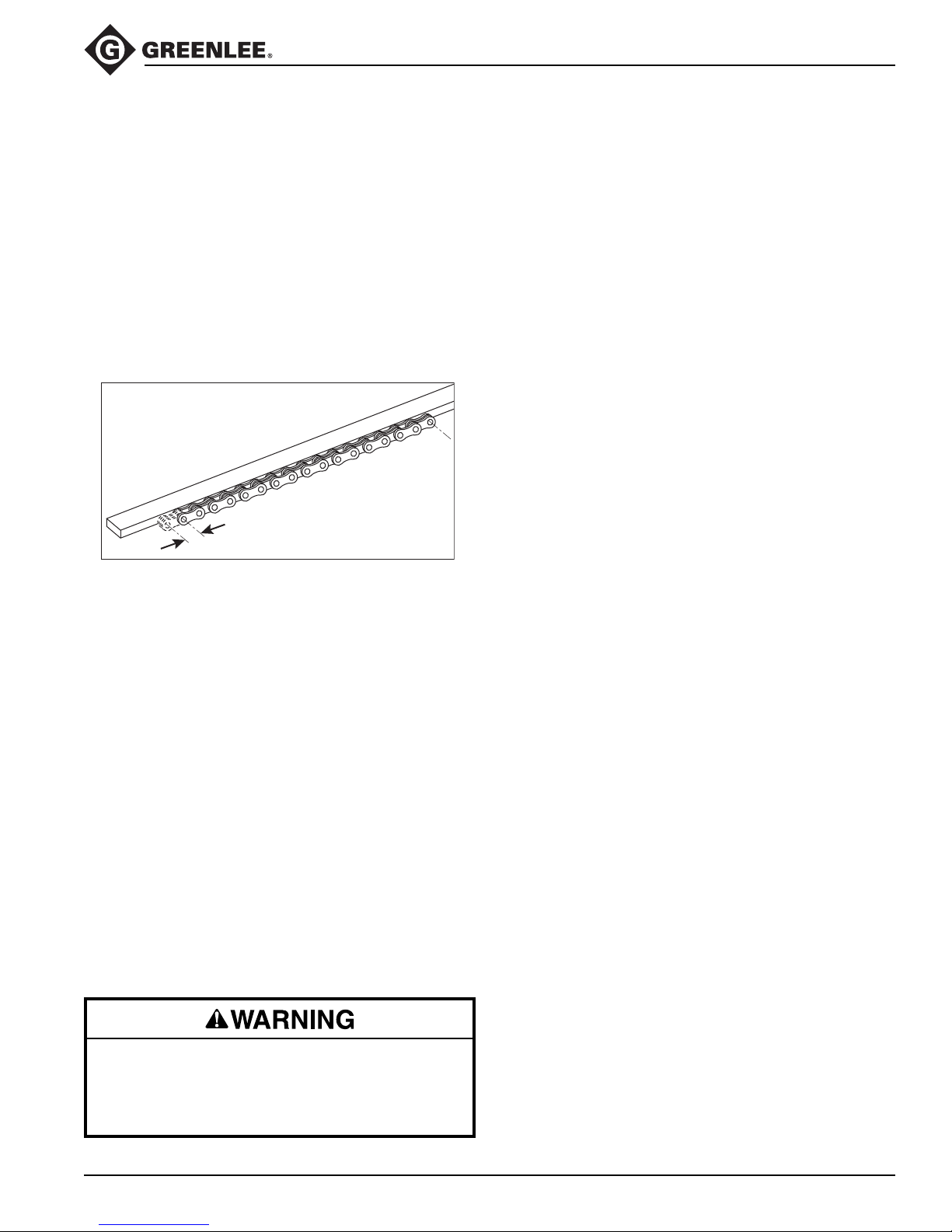
5. Lay the chain against a straightedge. Slide one
end of the chain back and forth to check free play.
See illustration below. If free play is more than 9mm
(3/8"), replace the chain. Replace the chain if any
links bind.
FREE PLAY
Inspecting the Commutator Brushes
(every 40 hours)
1. Remove two brush caps (116). Remove two
brushes (101).
2. Measure the brushes. Replace both brushes if either
brush is less than 9mm (3/8") long.
6. Lubricate the chain with 80W-90W gear oil.
7. Remove the ratchet pawl (17) and compression
spring (18). Apply multipurpose NLGI Grade 2
grease (such a Mobilgrease® HP or Amoco
Permalub) to all working surfaces. Replace the
spring and pawl.
8. Assemble the chain (11).
Note: Install the clip of each connecting link so that
the closed end of the clip faces the direction of chain
travel, as shown in the Exploded View.
9. Loosen, but do not remove, the four screws (19) that
secure the motor. Push the motor away from the
sprocket (12) to put tension on the chain. Tighten
the screws (19) to 10.8 Newton-meters (8 ft-lb).
10. Assemble in reverse order.
11. Plug the puller in and turn the puller ON. Listen for
the clicking noise of the anti-reversing mechanism
(ratchet pawl and compression spring). If you do not
hear this clicking noise, inspect and repair the puller.
Do not operate puller if the anti-reverse mechanism
is not working.
Failure to observe this warning could result in
severe injury or death.
Greenlee / A Textron Company 27 4455 Boeing Dr. • Rockford, IL 61109-2988 USA • 815-397-7070
Page 28
Maintenance (cont’d)
2001-Series Easy Tugger Cable Pullers
Replacing the Frame
Electric shock hazard:
Disconnect the cable puller from
the power supply before servicing.
Failure to observe this warning could
result in severe injury or death.
Replace the frame if appears damaged. During disassembly, inspect each part. Replace any worn, damaged,
or missing parts with Greenlee replacement parts.
1. Remove the guard (2). Remove the lubricating screw
(3), washers (5-8) and capstan unit (9).
2. Remove the screw (13) and washer (14).
3. Remove the two bottom motor screws (20). Loosen
the two top motor screws (20).
4. Slide sprocket (12), capstan (9) with sprocket (15)
and chain (10) off of shafts.
5. Remove two top motor screws (20) and gearmotor
(36).
6. Remove isolator plate, clip and rivet (22-24).
Note: Insert along screwdriver through power cord
hole in frame to push isolater away from the frame.
7. Remove remaining components from frame.
8. Assemble items to the new frame in reverse order.
Notes: Replace any components that show signs
of wear or damage.
Install the clip of the connecting link so that the
closed end of the clip faces the direction of chain
travel, as shown in the Exploded View.
Troubleshooting the Electrical Circuit
Electric shock hazard:
Disconnect the cable puller from
the power supply before servicing.
Failure to observe this warning could
result in severe injury or death.
See the wiring diagram. Use a continuity checker to
check the electrical circuit. Lack of continuity in the
following procedure indicates that a repair is necessary.
1. Unplug the puller.
2. Set the switches to ON.
3. Place the probes of the continuity checker across
the following terminals of the cable puller. All of
these pairs of terminals should have continuity.
To check the switches:
A and B
D and E (220-volt models only)
To check the connectors:
B and C
D and E (120-volt model only)
F and G (120-volt model only)
E and F (220-volt model only)
G and H (220-volt model only)
To check the motor:
A and D
If the motor fails this check, inspect the motor components (brushes, armature, and wires). Replace any parts
that are worn or damaged. Replace both brushes if
either brush measures less than 3/8" long.
Greenlee / A Textron Company 28 4455 Boeing Dr. • Rockford, IL 61109-2988 USA • 815-397-7070
Page 29
2001-Series Easy Tugger Cable Pullers
Troubleshooting
Should the puller become inoperative, refer to the troubleshooting table below. While performing any repairs, inspect
the motor, capstan, and drivetrain.
Problem Probable Cause Probable Remedy
Motor will not run. No power at supply circuit. Check power supply with a voltmeter.
See the Specifications section of this
manual.
Faulty switch or wiring. Check the switch and wiring for
continuity.
Motor faulty. Check the motor and wiring for
continuity. Check condition of brushes.
Replace any worn or damaged items.
Replace motor.
Capstan does not rotate while Chain broken. Replace chain.
motor is running.
Broken sprocket in gearbox or stripped Remove and disassemble gearmotor
shaft in motor. unit. Replace any worn or damaged
drive components.
Greenlee / A Textron Company 29 4455 Boeing Dr. • Rockford, IL 61109-2988 USA • 815-397-7070
Page 30
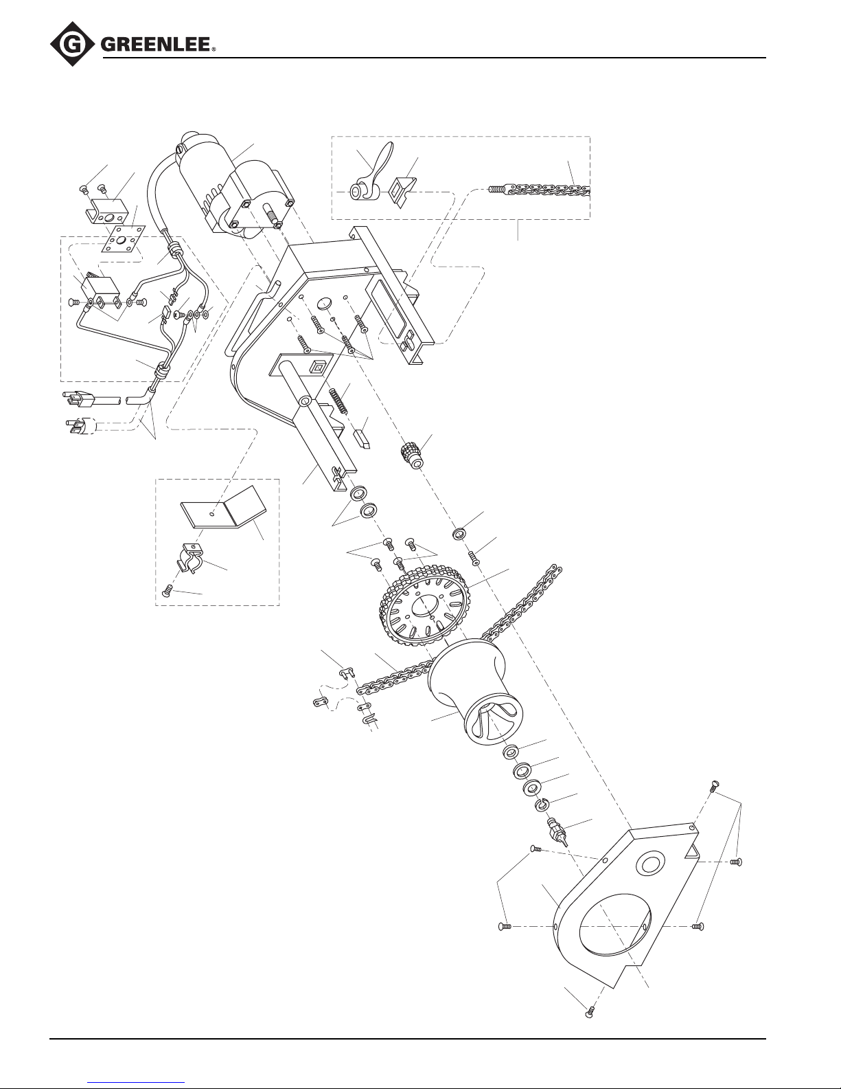
Exploded View
2001-Series Easy Tugger Cable Pullers
32
34
27
31
35
33
29
31
30
25
28
27
24
26
23
36
22
21
20
15
38
18
17
19
39
40
37
16
14
13
15
12
11
Greenlee / A Textron Company 30 4455 Boeing Dr. • Rockford, IL 61109-2988 USA • 815-397-7070
10
9
1
8
6,7
5
4
3
2
1
1
Page 31

Parts List
2001-Series Easy Tugger Cable Pullers
Key UPC No. Part No. Description Qty
* Items 6 and 7 are used to limit the side-to-side movement of the capstan to 0.80 mm (1/32") maximum.
KIT
** 29825 50298259
DECALS
78-3310-
1 53194 90531949 Screw, self-tapping, #10-16 x .250" Phillips ................. 10
2 31046 50310461 Guard ............................................................................. 1
3 25521 50255215 Screw unit, lubricating .................................................... 1
4 51603 90516036 Washer, lock, .643 x 1.08 x .156" spring ........................ 1
5 52675 90526759 Washer, flat .687 x 1.75 x .125" ..................................... 1
6 52644 90526449 Washer, flat .625 x 1.00 x .031" ...................................... *
7 52645 90526457 Washer, flat .625 x 1.00 x .062" ...................................... *
8 16313 50163132 Washer, fibre, 1.312 x 1.750 x .032" .............................. 1
9 31040 50310402 Capstan unit ................................................................... 1
10 31044 50310445
11 53322 90533224 Connecting link ............................................................... 1
12 31043 50310437 Sprocket, #35, 60-tooth, Type A .................................... 1
13 52791 90527917 Screw, cap, #10-32 x .375" button head ........................ 1
14 53318 90533186 Washer, flat .211 x .625 x .047" ..................................... 1
15 52587 90525876 Screw, cap, 5/16-18 x .875" socket button head ............ 4
16 31042 50310429 Sprocket, #35, 10-tooth, Type B .................................... 1
17 30102 50301020 Pawl, ratchet .................................................................. 1
18 16309 50163094 Spring, compression, .210 x .300 x 1.62" ..................... 1
19 51667 90516672 Screw, cap, 1/4-20 x .625" button head socket .............. 4
20 25896 50258966 Washer, flat, 1.28 x 1.75 x .125", Fibre .......................... 2
21 32574 50325744 Frame unit ...................................................................... 1
22 31045 50310453 Plate, isolator ................................................................. 1
23 53307 90533070 Clip, spring 1.25" ............................................................ 1
24 53001 90530012 Rivet, pop, .125" ............................................................. 1
25 31047 50310470 Power cord unit (120-Volt) ............................................. 1
32579 50325795 Power cord unit (220-Volt) ............................................. 1
26 50750 90507509 Washer, lock, .200 x .373 x .023" .................................. 1
27 86049 91860490 Terminal, ring ................................................................. 4
28 51460 90514602 Screw, self-tapping, #10-32 x .375" Phillips head .......... 1
29 86104 91861047 Terminal, disconnect, #14-16 AWG ............................... 1
30 86103 91861039 Terminal, disconnect, #14-16 AWG ............................... 1
31 86009 91860091 Bushing, strain relief ....................................................... 2
32 86101 91861012 Circuit breaker (120-volt) ................................................ 1
86200 91862000 Circuit breaker (220-volt) ................................................ 1
33 32576 50325760 Cover, switch .................................................................. 1
34 50430 90504305 Screw, machine, #6-32 x .375", slotted pan head .......... 2
35 29708 50297082 Guard, switch ................................................................. 1
36 52022898 Gearmotor unit (120-volt) ............................................... 1
32578 50325787 Gearmotor unit (220-volt) ............................................... 1
37** 29825 50298259 Chain unit, vise, 24" ....................................................... 2
38** 29630 50296302 Handle ............................................................................ 2
39** 29638 50296388 Positioner ....................................................................... 2
40** 27831 50278312 Vise chain with screw ..................................................... 2
29936 50299360 Decal, capstan rotation .................................................. 1
30392 50303929 Decal, warning (damp) ................................................... 1
31071 50310712 Decal, warning ............................................................... 1
Chain, roller, #35 (70 pitches, including connecting link) ....
Vise chain unit (includes one each of items marked with **)
1
Greenlee / A Textron Company 31 4455 Boeing Dr. • Rockford, IL 61109-2988 USA • 815-397-7070
Page 32
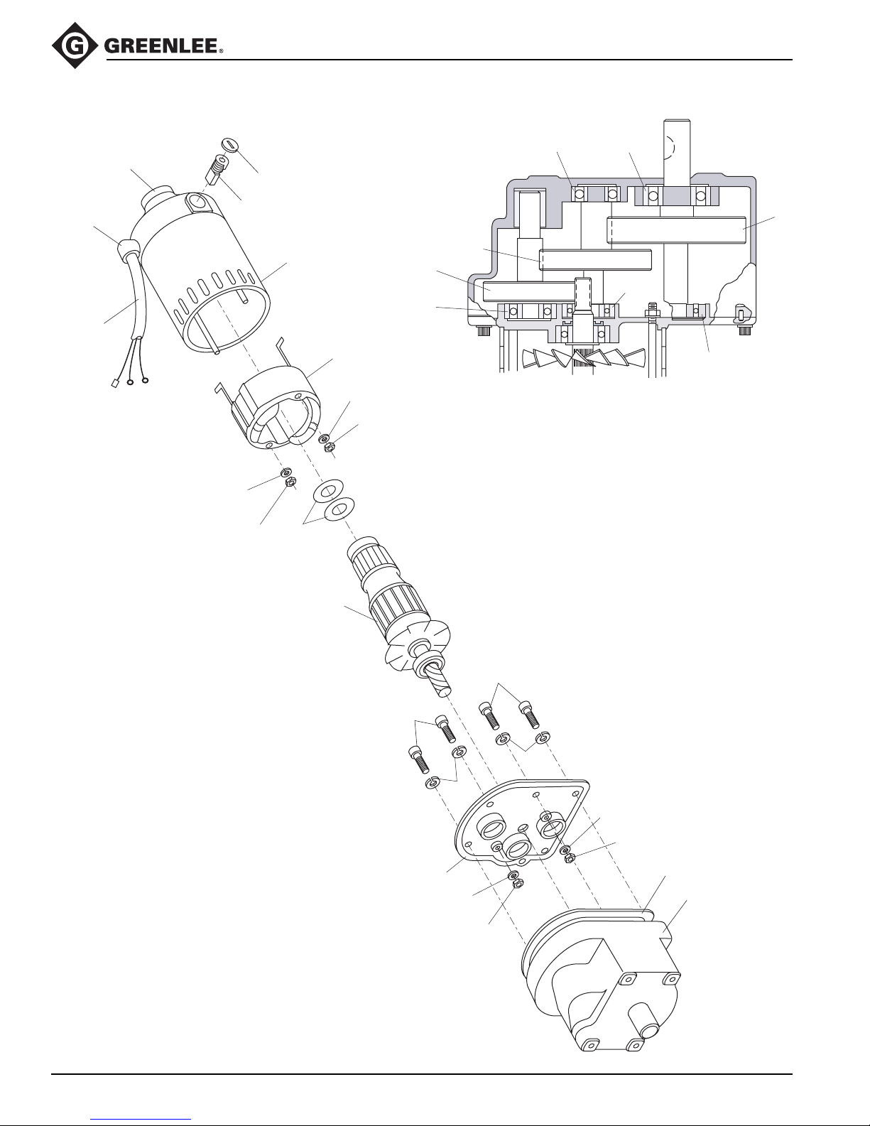
Exploded View—Motor
2001-Series Easy Tugger Cable Pullers
115
114
103
109
101
108
116
104
12
113
109
108
117
120
118
120
121
119
120
120
100
111
105
110
109
111
110
109
108
106
107
108
Greenlee / A Textron Company 32 4455 Boeing Dr. • Rockford, IL 61109-2988 USA • 815-397-7070
Page 33

Parts List—Motor
Key UPC No. Part No. Description Qty
100 86106 91861063 Armature......................................................... 1
101 86109 91861098 Brush .............................................................. 2
102 86110 91861101 Brush holder................................................... 2
103 86112 91861128 End cap assembly.......................................... 2
104 86180 91861802 115 volt motor frame assembly...................... 1
105 86181 91861810 Gearhousing cover......................................... 1
106 86182 91861829 Gasket ............................................................ 1
107 86183 91861837
108 51686 90516869 #10-32UNF hex nut........................................ 4
109 50750 90507509 #10 Internal lock washer, internal tooth ......... 4
110 50749 90507495 1/4 Lock washer, internal tooth...................... 4
111 50169 90501691 1/4-28 UNF x .875" head cap screw .............. 4
112 53323 90533232 Belleville washer ............................................ 2
113 86180 91861802 Field with cord (115 V) ................................... 1
114 06518 50065181 Cord assembly (115 V) .................................. 1
115 86083 91860830 Bushing, strain relief ...................................... 1
116 86113 91861136 Brush cap ....................................................... 2
117 86239 91862396 Drive shaft (includes gear, shaft, bearing) ..... 1
118 86241 91862418
119 86242 91862426
120 86243 91862434 Bearing ........................................................... 4
121 86244 91862442 Bearing ........................................................... 1
2001-Series Easy Tugger Cable Pullers
78-3310-
86201 91862019 220 volt motor frame assembly...................... 1
Gearhousing assembly
86202 91862027 Field (220 V)................................................... 1
32579 50325795 Cord assembly (220 V) .................................. 1
Drive shaft (includes gear, shaft, bearing).......
Output shaft (includes gear, shaft, bearing) ....
(includes #117-121) ......
1
1
1
Greenlee / A Textron Company 33 4455 Boeing Dr. • Rockford, IL 61109-2988 USA • 815-397-7070
Page 34
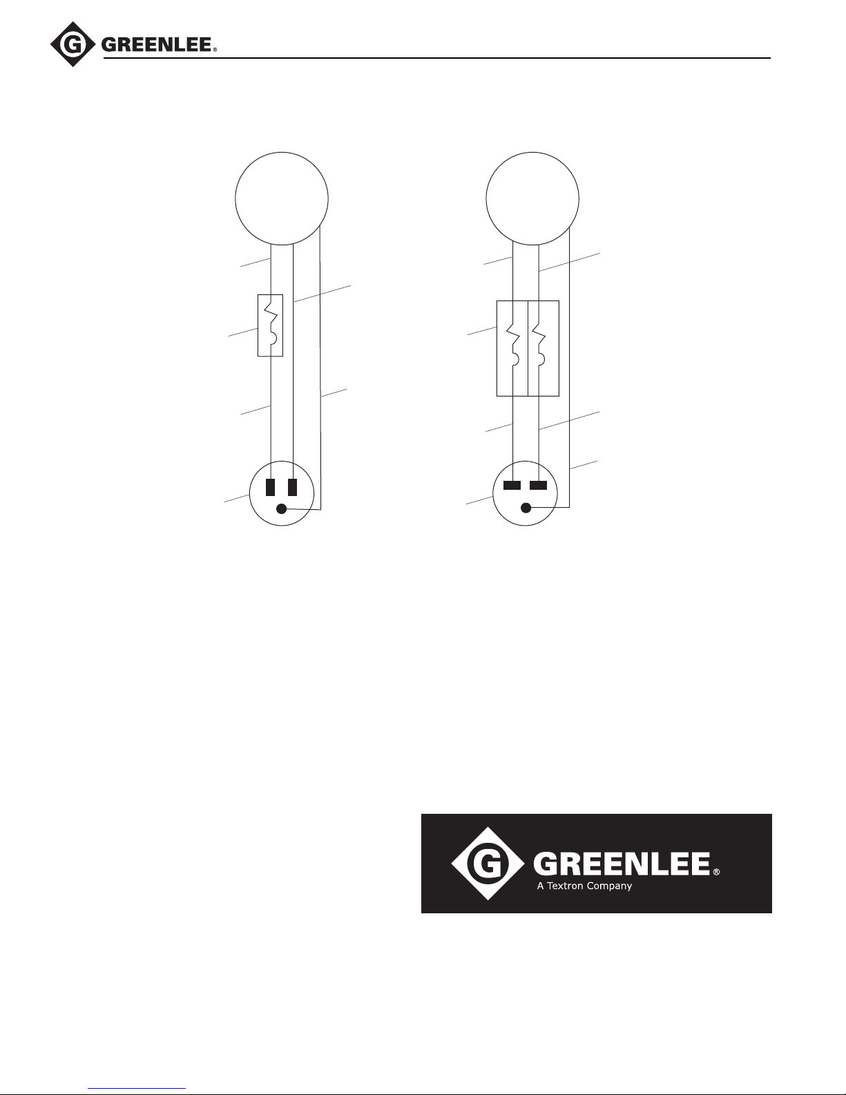
Wiring Diagram
2001-Series Easy Tugger Cable Pullers
Black
Switch/
Circuit Breaker
Black
Plug
Motor
D
A
B
CE
G
120-volt Model
Motor
F
Brown
White
Switch/
Circuit Breaker
Green
Brown
Plug
A
B
FHC
G
Blue
D
E
Blue
Green with
Yellow Stripe
220-volt Model
Greenlee / A Textron Company 34 4455 Boeing Dr. • Rockford, IL 61109-2988 USA • 815-397-7070
USA 800-435-0786 Fax: 800-451-2632
815-397-7070 Fax: 815-397-1865
Canada 800-435-0786 Fax: 800-524-2853
International +1-815-397-7070 Fax: +1-815-397-9247
4455 Boeing Drive • Rockford, IL 61109-2988 • USA • 815-397-7070
An ISO 9001 Company
www.greenlee.com
•
Greenlee Textron Inc. is a subsidiary of Textron Inc.
Printed in USA
 Loading...