

Page 1
INSTRUCTION MANUAL
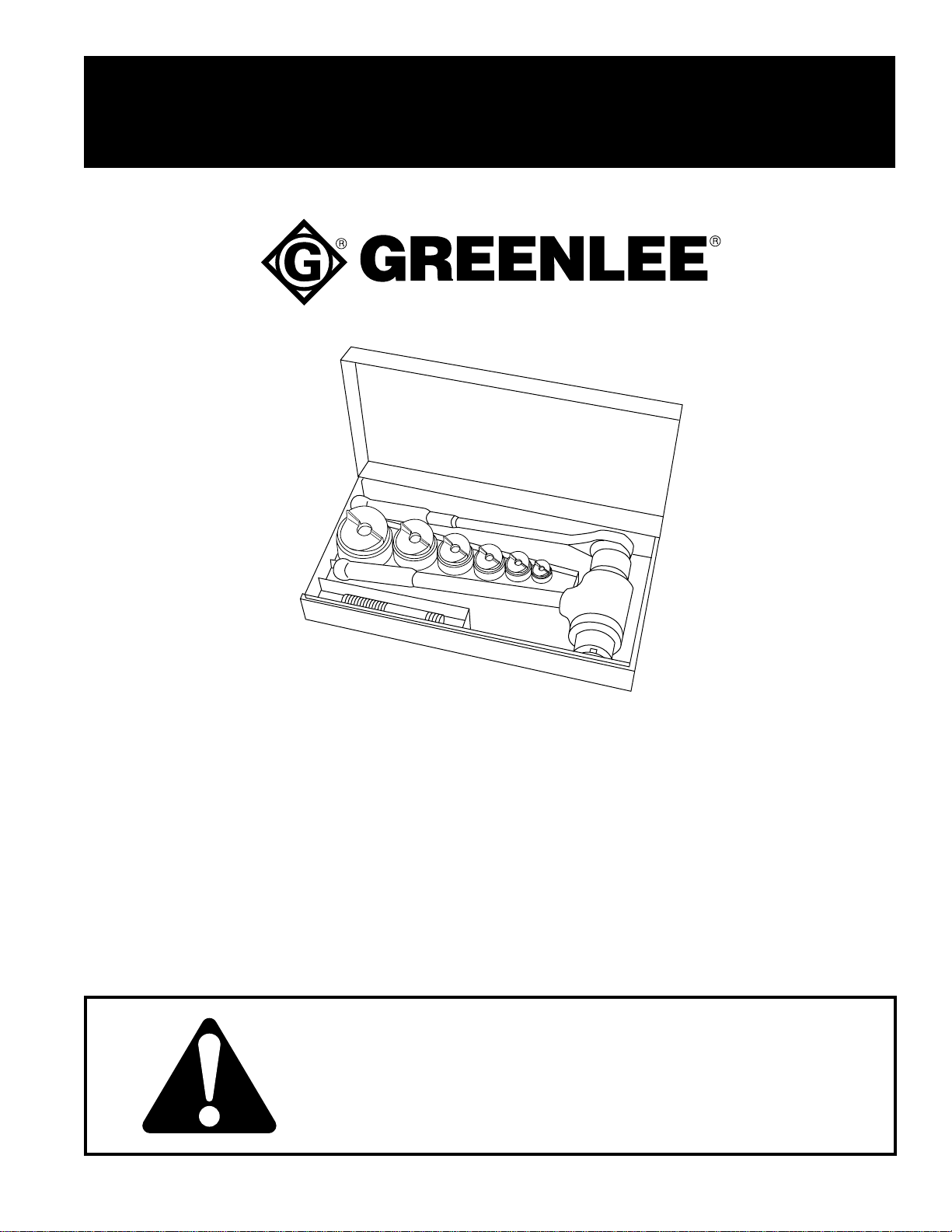
1904, 1904Pg, 1904PgSB,
and 1906SB
High Capacity
Ratchet Knockout Drivers
Read and understand all of the instructions and
safety information in this manual before operating
or servicing this tool.
999 9140.3 © 2001 Greenlee Textron IM 1037 REV 6 9/01
Page 2

High Capacity Ratchet Knockout Drivers
Table of Contents
Description .....................................................................2
Safety ............................................................................. 2
Purpose of this Manual .................................................. 2
Important Safety Information......................................3–4
Capacity Rating/Draw Stud Selection ............................4
Setup and Operation .................................................. 5–6
Standard Accessories ....................................................7
Maintenance............................................................... 8–9
Assembly of Ball Nut Unit............................................. 10
Exploded View ............................................................. 11
Parts List ......................................................................12
Description
Greenlee 1904, 1904Pg, 1904PgSB, and 1906SB High
Capacity Ratchet Knockout Driver sets are intended
to punch holes with Greenlee punches and dies. The
recirculating ball screw mechanism reduces by half the
amount of force necessary when compared to
conventional ratchet drivers.
These ratchet drivers can be used with Greenlee
standard or Slug-Buster® punches and dies to punch
round holes, from 1/2" actual size (12.7 mm) through 3"
conduit size (89.8 mm), in plastic, fiberglass, aluminum,
and mild steel. Greenlee Slug-Splitter® punches and
dies, available from 0.598" actual size (15.2 mm) though
2" conduit size (61.5 mm), are capable of punching
through all of these materials and stainless steel.
The maximum thickness of material that the punch can
penetrate depends on the size and type of the punch.
Refer to the Capacity Rating chart for individual punch
capacities.
Safety
Safety is essential in the use and maintenance of
Greenlee tools and equipment. This manual and any
markings on the tool provide information for avoiding
hazards and unsafe practices related to the use of this
tool. Observe all of the safety information provided.
All specifications are nominal and may change as design improvements occur. Greenlee Textron shall not be liable for damages
resulting from misapplication or misuse of its products.
Slug-Buster and Slug-Splitter are registered trademarks of
Greenlee Textron.
Loctite is a registered trademark of Loctite Corporation.
Purpose of this Manual
This manual is intended to familiarize all personnel with
the safe operation and maintenance procedures for the
following Greenlee tools:
1904, 1904Pg, 1904PgSB, and 1906SB
High Capacity Ratchet Knockout Drivers
Keep this manual available to all personnel.
Replacement manuals are available upon request at no
charge.
KEEP THIS MANUAL
Greenlee Textron / Subsidiary of Textron Inc. 2 4455 Boeing Dr. • Rockford, IL 61109-2988 USA • 815/397-7070
Page 3
High Capacity Ratchet Knockout Drivers
IMPORTANT SAFETY INFORMATION
SAFETY
ALERT
SYMBOL
This symbol is used to call your attention to hazards
or unsafe practices which could result in an injury or
property damage. The signal word, defined below,
indicates the severity of the hazard. The message
after the signal word provides information for
preventing or avoiding the hazard.
Immediate hazards which, if not avoided, WILL
result in severe injury or death.
Hazards which, if not avoided, COULD result in
severe injury or death.
Hazards or unsafe practices which, if not avoided,
MAY result in injury or property damage.
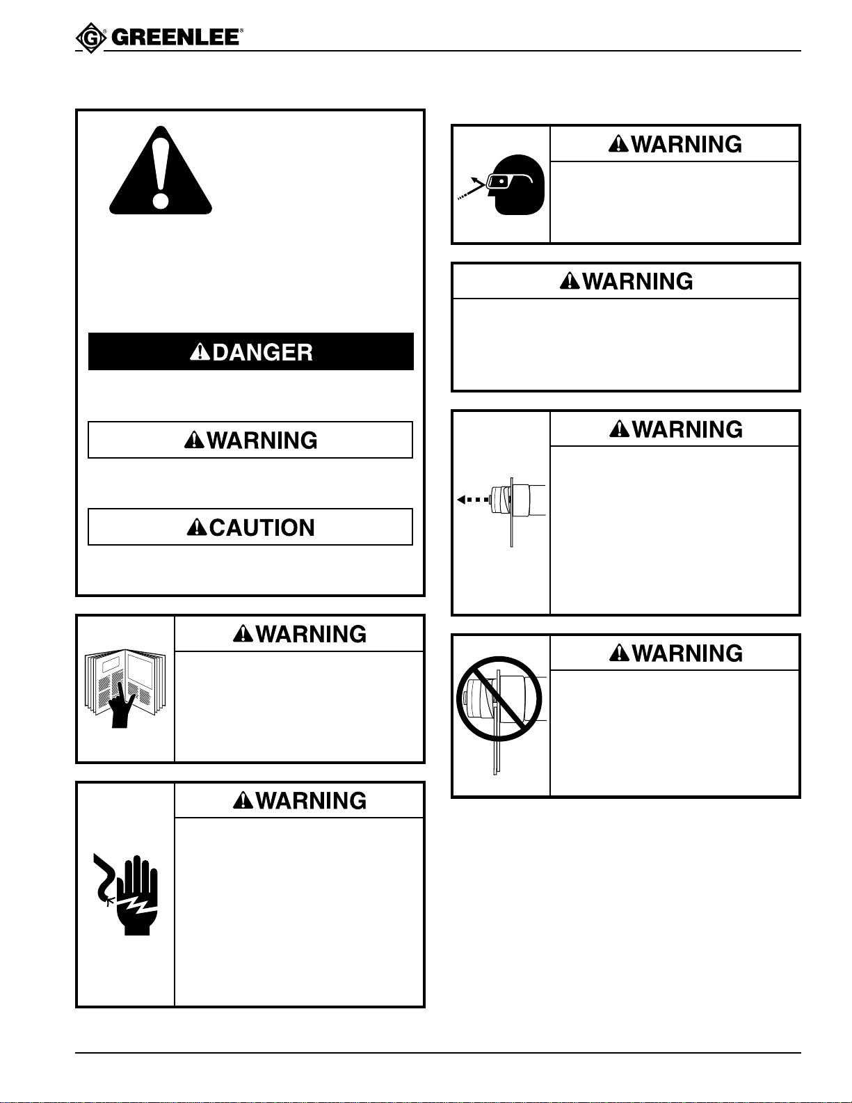
Wear eye protection.
Failure to wear eye protection can
result in serious eye injury from
flying debris.
Inspect the tool, punch, die, and draw stud before
each use for wear or damage. Replace the punch if
the cutting surfaces are not sharp. A damaged or
improperly assembled tool can break and strike
nearby personnel.
A component failure could throw
broken parts.
• Do not allow anyone to stand in
front of the punch unit.
• Close access doors or covers on
any equipment that is in line with
the punch unit.
Failure to observe this warning can
result in severe injury or death.
Read and understand all of the
instructions and safety information
in this manual before operating or
servicing this tool.
Failure to observe this warning can
result in severe injury or death.
Electric shock hazard:
Do not use this tool near live circuits.
This includes, but is not limited to,
the following:
• Near circuit breaker panels or fuse
boxes with energized circuits
• Near junction boxes with
energized circuits
Failure to observe this warning can
result in severe injury or death.
Greenlee Textron / Subsidiary of Textron Inc. 3 4455 Boeing Dr. • Rockford, IL 61109-2988 USA • 815/397-7070
Do not attempt to punch a hole
through two or more layers of
material. This will bend or break the
draw stud, and could throw parts
with great force.
Failure to observe this warning can
result in severe injury or death.
Page 4
High Capacity Ratchet Knockout Drivers
IMPORTANT SAFETY INFORMATION
Set up the tool properly. An improper setup could
cause a component to fail and strike nearby
personnel with great force.
• Thread the punch completely onto the draw stud.
All of the punch threads must be engaged by the
draw stud threads. Incomplete assembly could
cause a component failure.
• Use only Greenlee punches, dies and draw
studs. Other manufacturers’ components might
not withstand the forces generated by this punch
driver.
Failure to observe these warnings can result in
severe injury or death.
Do not exceed the rated capacity of this tool.
Exceeding the rated capacity could cause a
component failure, which could throw broken parts
with great force.
Failure to observe this warning can result in severe
injury or death.
• Do not add extensions (cheaters) to the handles.
When punching at maximum capacity, this tool
requires approximately 80 pounds of handle force.
Using excessive force can damage the punch
driver.
• Do not drive the ratchet after spindle motion stops.
Driving the ratchet after the spindle motion stops
can damage the punch driver.
Use this tool for the manufacturer’s intended
purpose only. Any other use can result in injury or
property damage.
Note: Keep all decals clean and legible, and replace
when necessary.
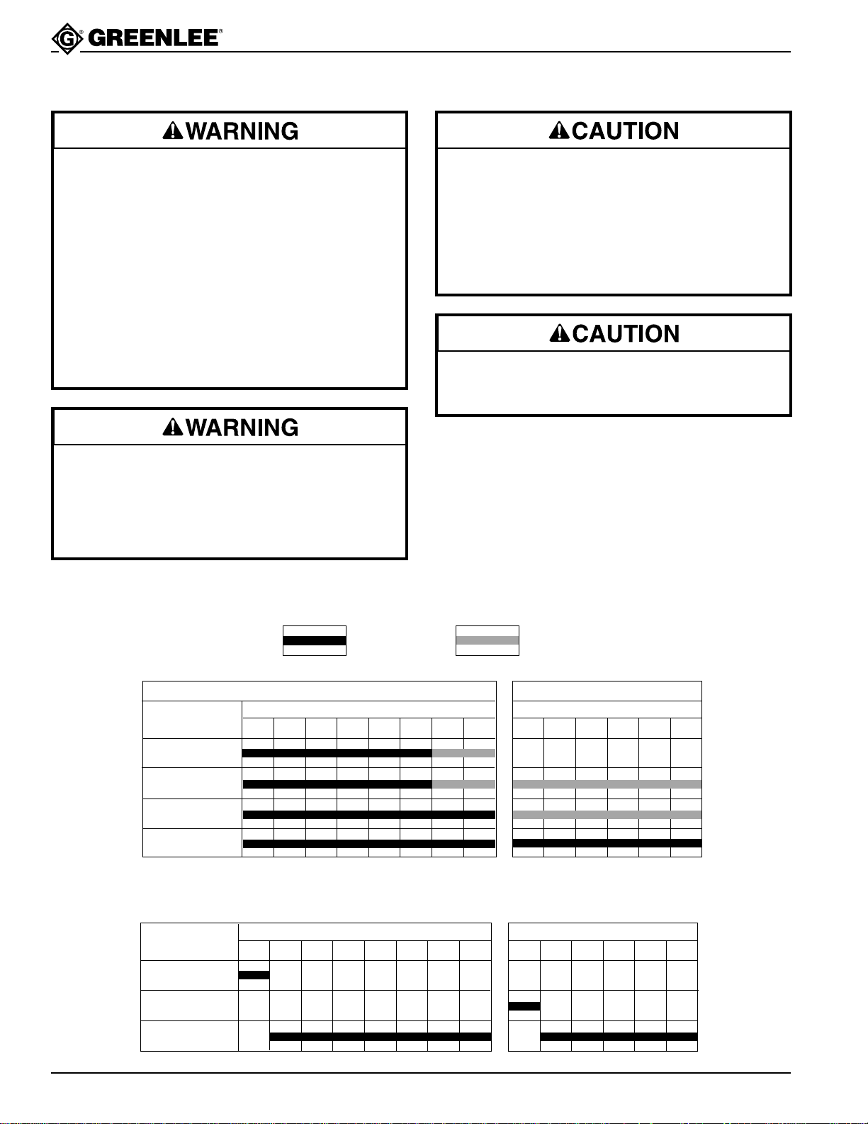
CAPACITY RATING
FREQUENT
USE
1904 with Slug-Splitter, Slug-Buster, or standard Greenlee punches and dies
MILD STEEL
MATERIAL
THICKNESS
10 GAUGE
12 GAUGE
14 GAUGE
16 GAUGE
1/2 3/4 1 1-1/4 1-1/2 2 2-1/2 3
CONDUIT SIZE
DRAW STUD SELECTION
Standard and Slug-Buster Greenlee punches
DRAW STUD NO.
12097
30227
1/2 3/4 1 1-1/4 1-1/2 2 2-1/2 3
CONDUIT SIZE
MAXIMUM
CAPACITY
1904 with Slug-Splitter punches only
STAINLESS STEEL
CONDUIT SIZE
1/2 3/4 1 1-1/4 1-1/2 2
Slug-Splitter punches
CONDUIT SIZE
1/2 3/4 1 1-1/4 1-1/2 2
12099
Greenlee Textron / Subsidiary of Textron Inc. 4 4455 Boeing Dr. • Rockford, IL 61109-2988 USA • 815/397-7070
Page 5
High Capacity Ratchet Knockout Drivers
Setup and Operation
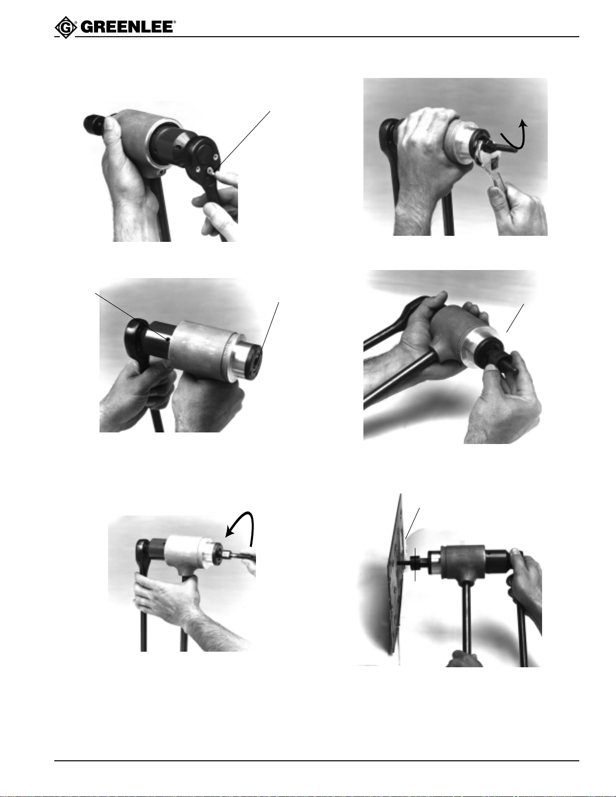
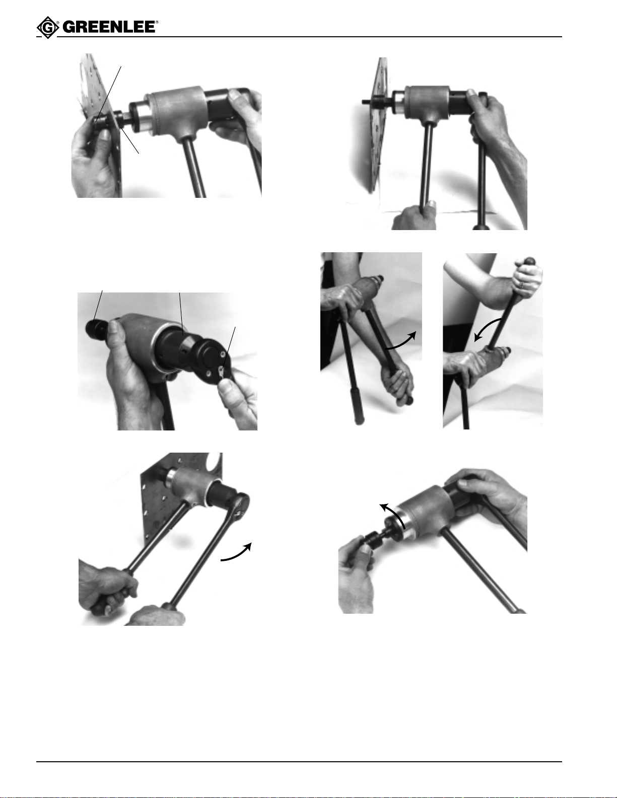
Set the ratchet driver to the starting position, as follows.
Ratchet Lever
1. Move the ratchet direction lever to the right.
Yellow will
show in
view hole
Spindle will be
close to end
2. Rotate the ratchet as shown. When the spindle is
fully extended, the view hole will be completely filled
with the yellow band.
4. Snug up the draw stud with a wrench.
Die
5. Install the die onto the stud so that the opening of
the die faces outward.
Draw
Stud
Die
3. Select the appropriate punch and die. Use the Draw
6. Insert the draw stud through the pilot hole.
Stud Selection Table to determine the corresponding
draw stud. Install the draw stud as shown.
Note: All draw studs for the 1904 have left-hand
threads.
Greenlee Textron / Subsidiary of Textron Inc. 5 4455 Boeing Dr. • Rockford, IL 61109-2988 USA • 815/397-7070
Page 6
High Capacity Ratchet Knockout Drivers
Draw Stud Threads
Punch
7. Thread the punch onto the stud so that the cutting
surfaces of the punch are toward the material.
Note: This end of the stud and the punch have righthand threads.
Note: Do not unthread the stud.
Line up using
crosshairs on die
Input Hub
Ratchet Lever
10. Remove the driver assembly from the punched hole.
8. Push the ratchet direction lever to the left.
Punch
Direction
9. Turn the ratcheting handle counterclockwise.
Continue to ratchet until the punch is completely
through the material.
Do not drive the ratchet after spindle motion stops.
Driving the ratchet after the spindle motion stops can
damage the punch driver. If the spindle is at the end
of its stroke and the punch is not completely through,
unthread the punch and check the setup. The
spindle must be in the starting position and the stud
must be threaded completely into the spindle.
11. For rapid return, hold the assembly as shown.
Rotate the handle as shown until the spindle is fully
extended.
12. Remove the punch, die, and draw stud.
Greenlee Textron / Subsidiary of Textron Inc. 6 4455 Boeing Dr. • Rockford, IL 61109-2988 USA • 815/397-7070
Page 7
High Capacity Ratchet Knockout Drivers
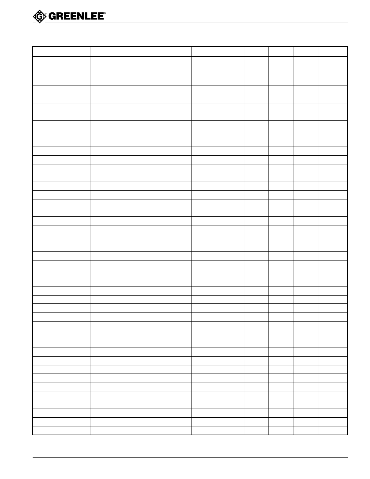
Standard Accessories
Part Number Nominal Size Metric Size Type 1904 1906SB 1904Pg 1904PgSB
Draw studs
501 2097.2 3/8" x 2-15/16" 1 1
503 0227.2 7/16" x 3-5/8" 1
501 2099.9 3/4" x 4-3/4" 1 1
Punches
502 1316.4 Pg-9 15.2 mm standard 1
503 1969.8 Pg-9 15.2 mm Slug-Buster 1
501 7700.1 Pg-11 18.6 mm standard 1
503 1970.1 Pg-11 18.6 mm Slug-Buster 1
501 7697.8 Pg-13 20.4 mm standard 1
503 1971.0 Pg-13 20.4 mm Slug-Buster 1
500 4006.5 1/2" conduit 22.5 mm standard 1
503 1756.3 1/2" conduit 22.5 mm Slug-Buster 1 1
503 1973.6 Pg-21 28.3 mm Slug-Buster 1
503 6882.6 Pg-21 28.3 mm standard 1
503 1757.1 3/4" conduit 28.3 mm Slug-Buster 1
503 6282.8 1-7/32" 30.5 mm standard 1
503 6284.4 1-7/32" 30.5 mm Slug-Buster 1
503 1758.0 1" conduit Slug-Buster 1
501 8331.1 Pg-29 37.0 mm standard 1
503 1975.2 Pg-29 37.0 mm Slug-Buster 1
503 1759.8 1-1/4" conduit 43.2 mm Slug-Buster 1
501 7687.0 Pg-36 47.0 mm standard 1
503 1976.0 Pg-36 47.0 mm Slug-Buster 1
503 1760.1 1-1/2" conduit 49.6 mm Slug-Buster 1
501 7690.0 Pg-48 60.0 mm standard 1
503 1978.7 Pg-48 60.0 mm Slug-Buster 1
503 1761.0 2" conduit 61.5 mm Slug-Buster 1
Dies
503 2002.5 Pg-9 15.2 mm 1 1
503 2003.3 Pg-11 18.6 mm 1 1
503 2004.1 Pg-13 20.4 mm 1 1
501 4722.6 1/2" conduit 22.5 mm 1 1 1
503 2006.8 Pg-21 28.3 mm 1 1
500 6972.1 3/4" conduit 28.3 mm 1
503 6279.8 1-7/32" 30.5 mm 1 1
500 4011.1 1" conduit 34.6 mm 1
503 2008.4 Pg-29 37.0 mm 1 1
500 4013.8 1-1/4" conduit 43.2 mm 1
503 2009.2 Pg-36 47.0 mm 1 1
500 4061.8 1-1/2" conduit 49.6 mm 1
503 2011.4 Pg-48 60.0 mm 1 1
500 4063.4 2" conduit 61.5 mm 1
Greenlee Textron / Subsidiary of Textron Inc. 7 4455 Boeing Dr. • Rockford, IL 61109-2988 USA • 815/397-7070
Page 8
Maintenance
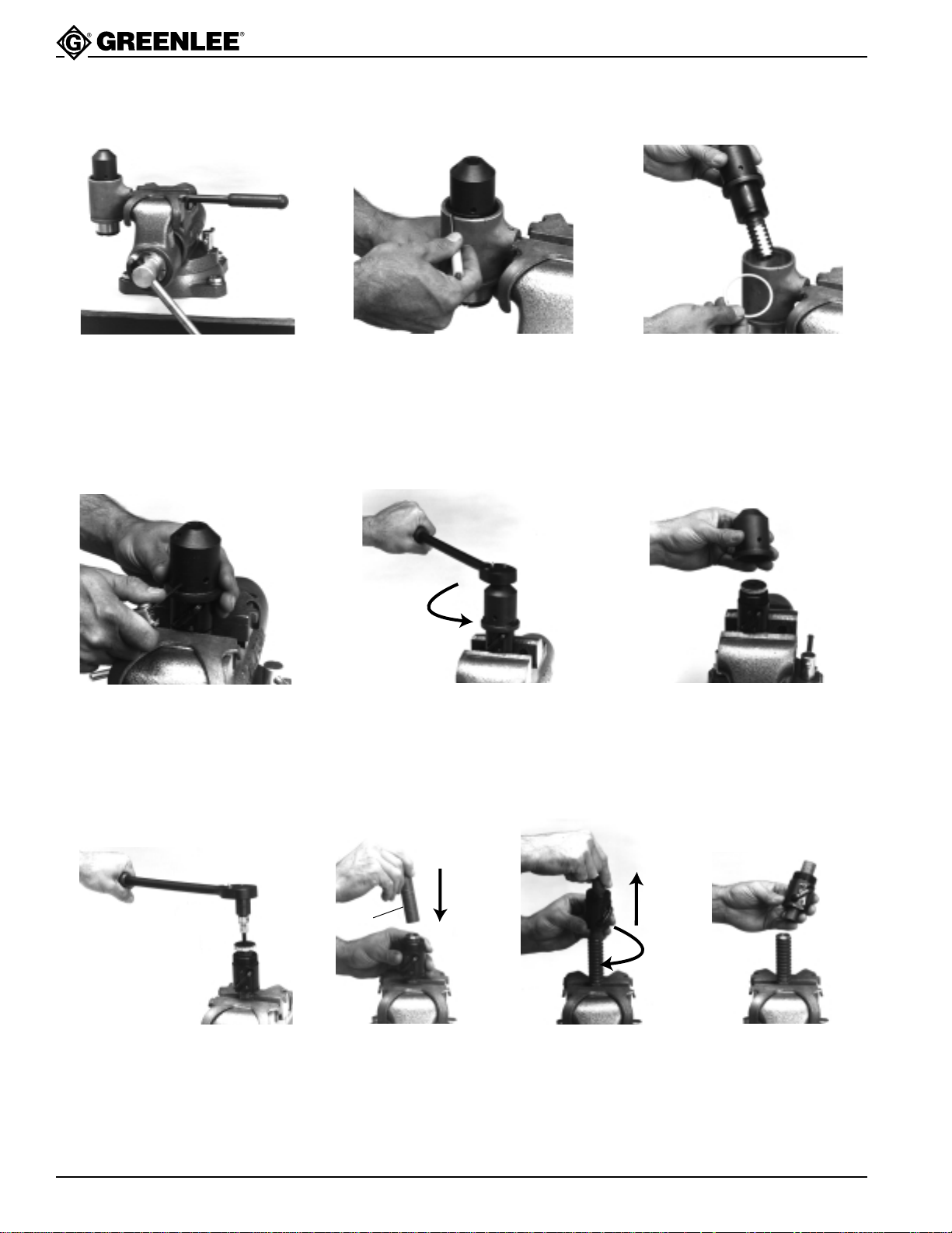
Disassembly (photos 1-3)
High Capacity Ratchet Knockout Drivers
1. Mount unit to be repaired in
sturdy vise as shown. Remove
ratchet wrench (1) from hub by
depressing locking detent with an
appropriate tool.
Disassembly of Spindle Hub Unit (photos 4-10)
4. Mount unit securely in vise as
shown. Care must be taken to
not damage ball return tube of
the ball nut when gripping with
vise. Then remove 3 set screws
(6) from unit and discard screws
(new screws must be used
during reassembly).
2. To remove retaining ring (3), use
small screwdriver to remove tab
end of ring from groove and
“spiral” ring out of groove as
shown in photo.
5. Remove hub (7) with ratchet (1)
or any suitable 1/2" drive ratchet
or breaker bar. The hub was
tightened to a torque of 90 ft-lb to
100 ft-lb at the factory. Therefore,
a considerable amount of force
will be necessary to loosen.
3. After retaining ring is removed,
lift spindle hub unit (5) out of
sleeve casting (20).
6. Unscrew hub and remove from
ball nut.
Arbor
7. To complete disassembly, remove
above unit from vise and regrip on
“flats” of spindle (13). Use “soft”
jaws to prevent damage from hard
vise jaws. Loosen flat head screw
(8) with Allen wrench and remove
top washer (9).
Greenlee Textron / Subsidiary of Textron Inc. 8 4455 Boeing Dr. • Rockford, IL 61109-2988 USA • 815/397-7070
8, 9, 10. A suitable arbor is needed to perform this operation. Arbor must
have a diameter of approximately 0.840/0.800 inches. Hold arbor flush to
end of spindle. With other hand, screw ball nut toward and onto arbor as
shown. Once ball nut is completely on arbor, ball nut and arbor can be
moved away from spindle (arbor retains ball bearings in ball nut.)
IMPORTANT: If arbor is not the proper size, or is removed from ball nut while apart, balls will fall
free from the race. Should this happen, refer to Assembly of Ball Nut at the end of
the Maintenance section.
Page 9
High Capacity Ratchet Knockout Drivers
Maintenance (cont’d)
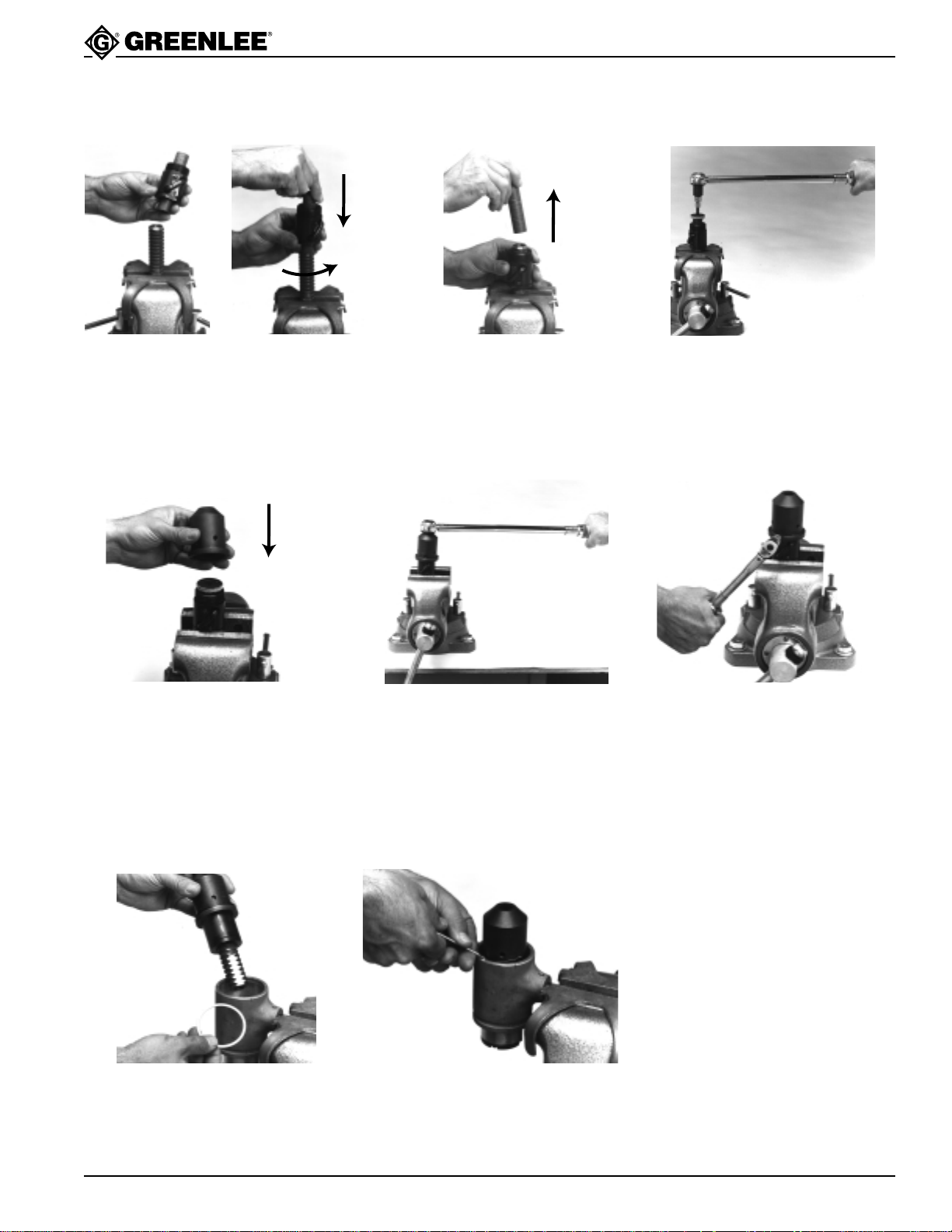
Assembly of Spindle Hub Unit (photos 11-17)
11, 12. Place ball nut with arbor to
end of spindle as shown.
15. Reassemble hub (7) to ball nut.
(Note how unit is held in vise.)
13. Carefully rotate ball
nut down the arbor
and onto the spindle.
Note: Spindle has lefthand lead.
16. Torque hub to ball nut to 90 ft-lb
to 100 ft-lb. (Use 1/2" drive
torque wrench of appropriate
torque capacity.)
14. Replace top washer (9) and
replace flat head cap screw (8).
With a torque wrench and Allen
socket, torque screw to 35 ft-lb
to 45 ft-lb.
17. Replace three set screws (6)
and torque to 70 ft-lb to 80 ft-lb.
(Use Allen socket and torque
wrench of appropriate capacity.)
Note: All tightening torques
must be met to ensure
satisfactory operation.
Assembly of Ball Nut Unit into Sleeve (photos 18, 19)
Thrust Bearings
If thrust bearing set (14, 15 & 16)
show any significant damage,
replace as a complete set. Lubricate
with Molycote-G.
Balls
If any balls need replacement, a
complete set should be ordered to
18, 19. Refer to these photos and reassemble in the reverse order. Inspect
and re-install thrust bearings. Install spindle hub unit, wave washer
(4), and retaining ring (3). Be sure to seat the retaining ring
completely in the groove.
Greenlee Textron / Subsidiary of Textron Inc. 9 4455 Boeing Dr. • Rockford, IL 61109-2988 USA • 815/397-7070
ensure proper consistency of size.
Page 10
High Capacity Ratchet Knockout Drivers
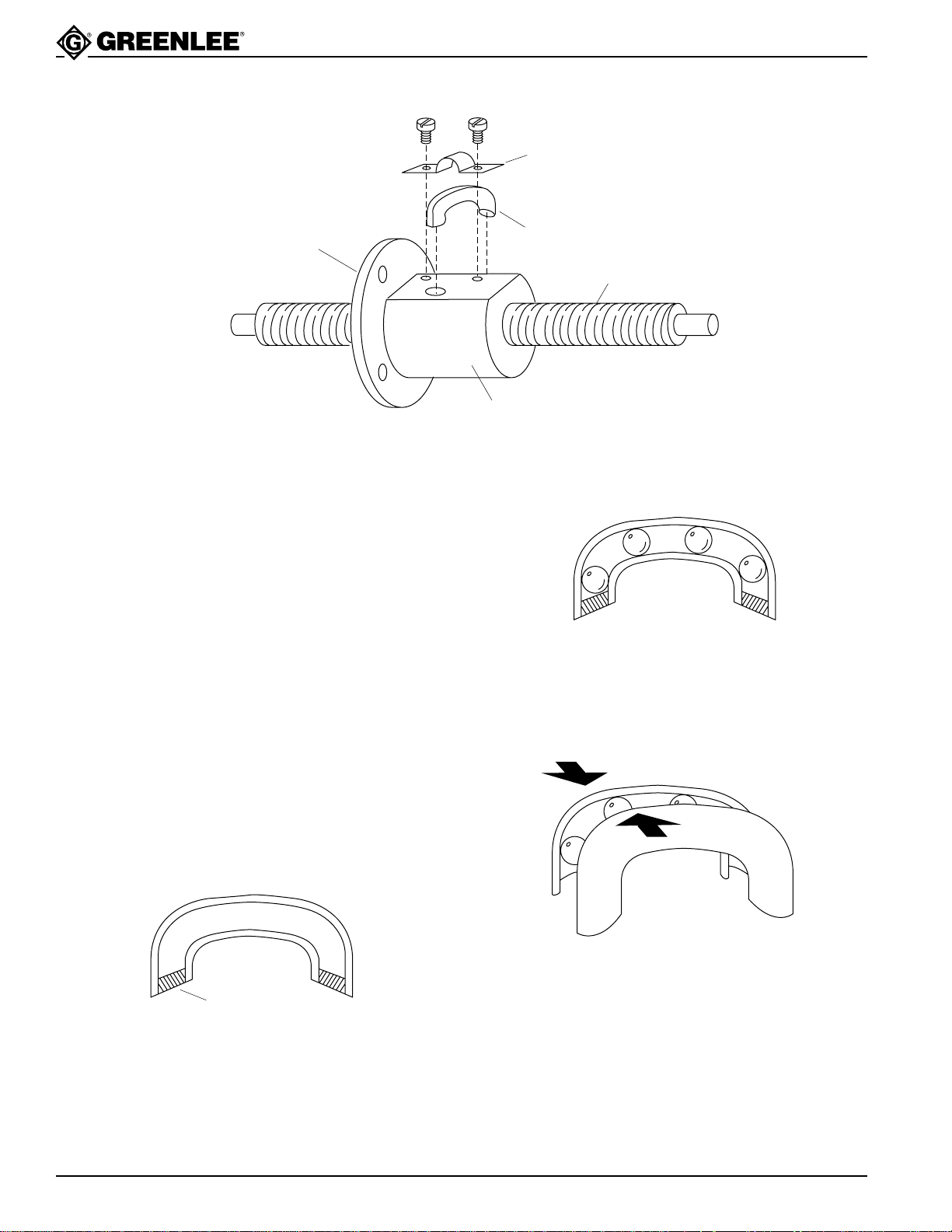
Assembly of Ball Nut Unit
CLAMP
MOUNTING
FLANGE
1. Remove the return tube clamp and the return tube
from the ball nut.
2. Place the nut approximately midway on the spindle
(13) and align the ball grooves in the nut with those
on the screw.
3. Place a short length of rod or dowel into one return
tube hole to prevent loss of balls.
4. Place balls successively into the other return tube
hole, rotating the screw so that the balls are fed
along the thread and through the nut, until the ball
circuit is completely full.
5. Remove dowel or rod, being careful to not rotate the
nut. The balls must not be in the return tube holes—
balls must only be in the mesh between the ball nut
and screw.
6. On both ends of the return tube, place a small
amount of light grease.
RETURN
TUBE
SPINDLE
BALL NUT
7. Load this half tube half full of balls.
8. Place the second half of the return tube over the
balls and hold the two halves tightly together.
PRESS
TIGHTLY
TOGETHER
9. Place the return tube ends into the return tube holes
in the nut (the grease in the tube will prevent the
GREASE
balls from dropping out).
10. Place the tube clamp over the tube (taking care to
keep the two halves together) and secure with the
clamp screws.
Greenlee Textron / Subsidiary of Textron Inc. 10 4455 Boeing Dr. • Rockford, IL 61109-2988 USA • 815/397-7070
Page 11
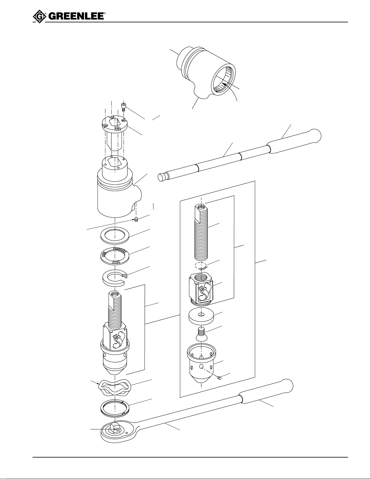
Exploded View
High Capacity Ratchet Knockout Drivers
Apply a drop
of Loctite
removable
thread
locker #242
®
Torque
to 20-30
inch-pounds
22
21
20
Torque
to 35-45
inch-pounds
17
16
15
14
5
Lubricate the I.D.
of this sleeve with
a light coat of
Molycote-G
18
13
10
12
11
9
8
19
SPINDLE HUB UNIT
may be repaired
only at authorized
service centers
NOTE:
If any balls are in
need of replacement,
a complete set should
be ordered to ensure
proper consistency
of size.
7
6
Lubricate
4
with light
machine oil
3
2
Locking detent
Greenlee Textron / Subsidiary of Textron Inc. 11 4455 Boeing Dr. • Rockford, IL 61109-2988 USA • 815/397-7070
1
Page 12

Parts List
High Capacity Ratchet Knockout Drivers
Key Catalog No. Description Qty.
1 502 0495.5 Wrench, ratchet ................................................................................. 1
2 502 3258.4 Grip............................................................................................... 1
3 905 3497.2 Ring, retaining, 2.25 spiral internal.................................................... 1
4 905 3248.1 Washer, wave, 1.90 x 2.15 x .480 spring .......................................... 1
5 503 3554.5 Hub unit, spindle ............................................................................... 1
6 905 5361.6 Screw, set, 1/4 - 28 x .125 socket ................................................ 3
7 503 0223.0 Hub, input..................................................................................... 1
8 905 3247.3 Screw, machine, 7/16 - 14 x .750 flat head.................................. 1
9 503 0224.8 Washer, flat, .468 x 1.37 x .250.................................................... 1
10 503 3548.0 Ball/Nut unit, square..................................................................... 1
11 503 0221.3 Ball/Nut, square ....................................................................... 1
12 503 0400.3 Ball, .156 diameter......................................................... 84 (± 4)
13 503 3547.2 Spindle, .970 x 4.60................................................................. 1
14 503 0249.3 Washer, thrust, 1.12 x 2.09 x .250 (stepped) .................................... 1
15 905 3251.1 Bearing, thrust, 1.50 x 2.17 x .078 .................................................... 1
16 905 3250.3 Washer, thrust, 1.508 x 2.16 x .125 .................................................. 1
17 905 3600.2 Screw, set, 1/4 - 20 x .437 flat point socket ...................................... 1
18 503 0225.6 Handle unit ........................................................................................ 1
19 502 3258.4 Grip ................................................................................................. 1
20 503 3553.7 Sleeve, ratchet driver ........................................................................ 1
21 503 3549.9 Insert, alignment................................................................................ 1
22 905 1762.8 Screw, cap, #6 - 32 x .375 socket head ............................................ 4
503 2483.7 Decal - Caution (not shown).............................................................. 1
503 2600.7 Decal - Max. Capacity (not shown) ................................................... 1
Greenlee Textron / Subsidiary of Textron Inc.
4455 Boeing Drive, Rockford, IL 61109-2988 USA
Customer Service (International): 815/397-7070 • Fax: 815/397-9247
Customer Service (North America): 800/435-0786 • USA Fax: 800/451-2632, 815/397-1865
Canada Fax: 800/524-2853
www.greenlee.textron.com
Greenlee Textron / Subsidiary of Textron Inc. 12 4455 Boeing Dr. • Rockford, IL 61109-2988 USA • 815/397-7070
Printed in the USA
 Loading...