

Page 1
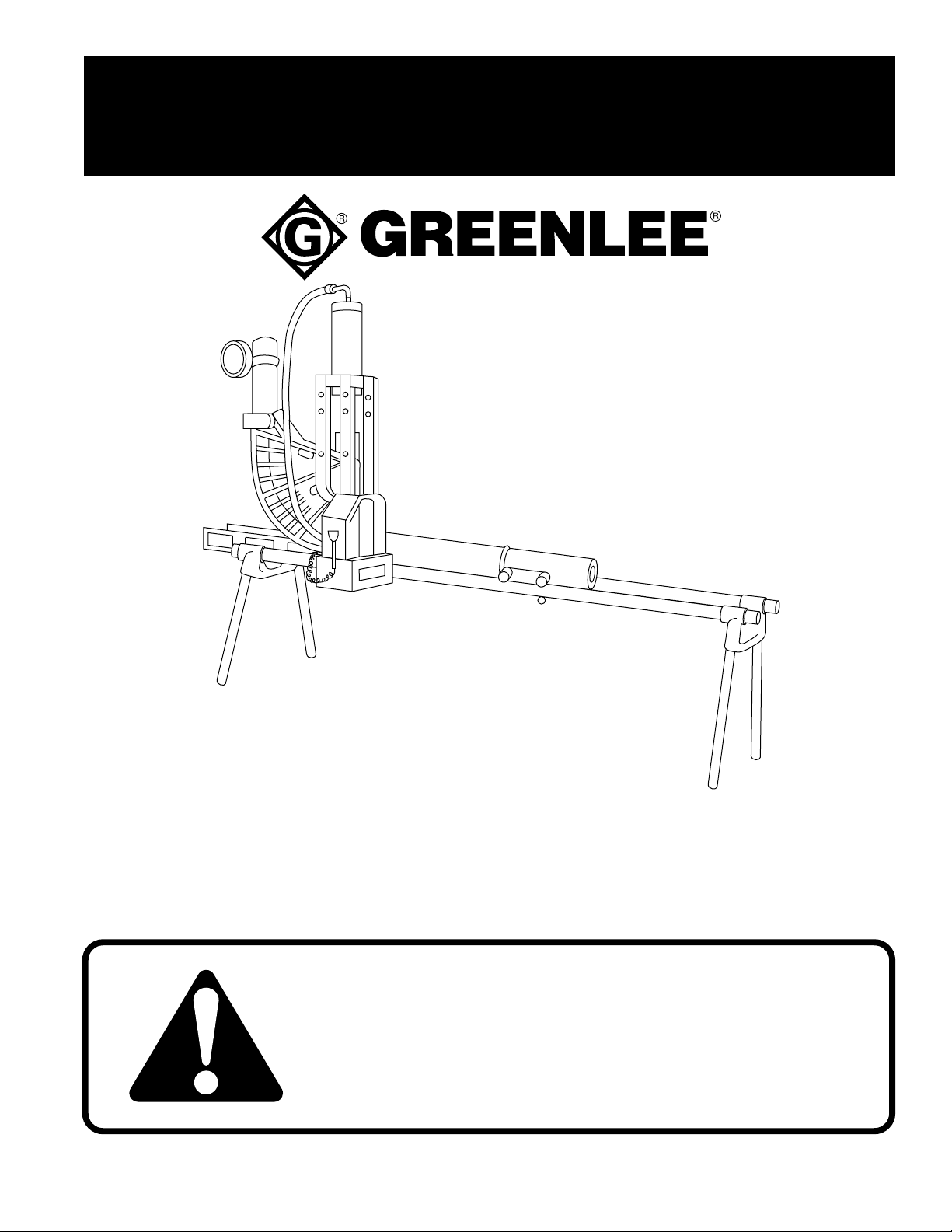
OPERATION, SERVICE AND PARTS
INSTRUCTION MANUAL
1813 BENDING TABLE
FOR 881 HYDRAULIC BENDER
Read and understand this material before operating or
servicing this bender. Failure to understand how to
safely operate this bender could result in an accident
causing serious injury or death. This tool should only
be operated by qualified personnel.
999 6389.2 © 1996 GreenleeTextron Inc. IM 955 REV 8 8/96
Page 2
1813 Bending T able
Table Of Contents
Introduction ...........................................................................................................2
Safety Information............................................................................................. 2-3
Setup.....................................................................................................................4
Mounting 881 Bender ...........................................................................................4
Adjusting Ram Position..................................................................................... 5-6
Bending.................................................................................................................7
Exploded View ......................................................................................................8
Parts List ...............................................................................................................9
Introduction
The Greenlee No. 1813 Bending Table is designed to make your Greenlee No. 881 Hydraulic Bender easier to use.
Loading is faster and easier. The vertical, bench-high bending means greater control and freedom of movement for
the operator and less fatigue, too. Use of the bending table also simplifies difficult bending operations, reducing
bending time and increasing accuracy.
SAFETY
ALERT
Immediate hazards which WILL result in severe personal
injury or death.
SYMBOL
The symbol above is used to call your attention
to instructions concerning your personal safety.
Watch for this symbol. It points out important safety
precautions. It means “ATTENTION! Become alert!
Your personal safety is involved!” Read the
message that follows and be alert to the possibility
of personal injury or death.
Safety is a critical factor in the design of Greenlee equipment. The best program starts with a safety-conscious
operator. The information highlighted in this bulletin describes operating practices for the benefit of the workers who
will use our equipment in their daily jobs. Comments from users are appreciated.
A person who has not read and does not understand all
operating instructions is not qualified to operate this tool.
Hazards or unsafe practices which COULD result in
severe personal injury or death.
Hazards or unsafe practices which COULD result in
minor personal injury or property damage.
Failure to read and understand safety instructions may
result in severe injury or death.
SA VE THESE INSTRUCTIONS
Greenlee Textron Inc. / Subsidiary of Textron Inc.
2
4455 Boeing Dr., Rockford, IL 61109-2988 815/397-7070
Page 3

1813 Bending T able
• Operate the power pump only at
the correct voltage and frequency
marked on the nameplate. Use a
properly grounded outlet.
• Turn off and unplug the
power pump when changing
accessories, performing service
and when idle.
• Do not operate with a damaged
cord set or with hydraulic hoses
which are abraided or cracked.
• Do not operate the power pump
in the rain or wet locations.
• Read all operating instructions.
• Clean hydraulic quick-change couplers before
making connections. Hand-tighten firmly to
engage all threads. Do not use a wrench.
• Place hydraulic control lever on power pumps in
the return position before starting the motor.
• Do not operate power equipment unattended.
• Do not operate hydraulic rams beyond (their
recommended) extended length.
• Properly position and engage all pins and rollers
before operating hydraulic bending equipment.
• Follow recommended service procedures.
• Operate power equipment in uncluttered areas
providing good footing and support.
• Keep others a safe distance from the work area.
• Use only original equipment or Greenlee specified
replacement parts and accessories.
Failure to observe these warnings could result in
severe injury or death.
Greenlee Textron Inc. / Subsidiary of Textron Inc.
3
4455 Boeing Dr., Rockford, IL 61109-2988 815/379-7070
Page 4

1813 Bending T able
Setup
Note: Two 10-foot lengths of 2" galvanized conduit are
required for the table bed. These are not
furnished with the No. 1813 Bending Table.
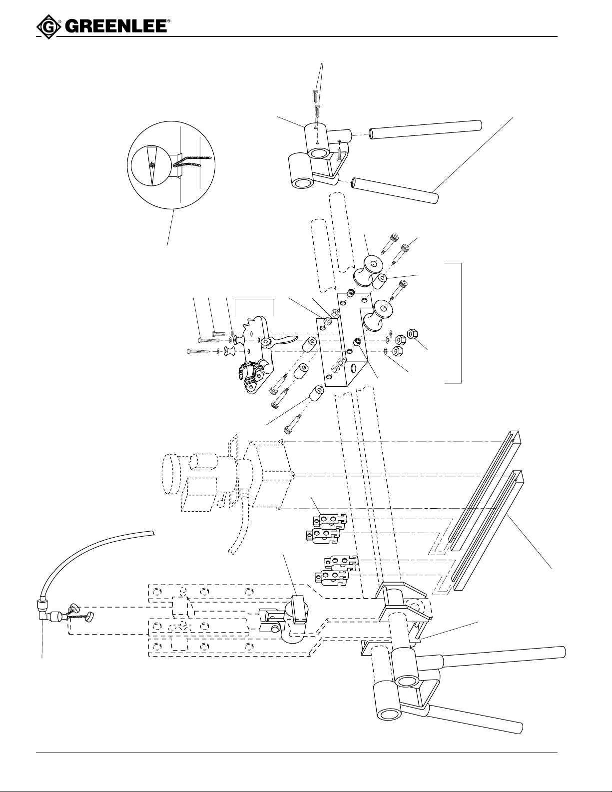
1. Insert each of the four legs (7) into the sockets of the
two leg supports (1), and tighten each of the four
pipe mounting screws (2).
2. Keeping one of the leg assemblies to your right,
insert the two 10-foot lengths of 2" galvanized
conduit into that assembly and tighten the four pipe
mounting screws (2).
3. With the vise to your left, slide the pipe vise unit (3)
onto the two lengths of conduit. Now slide the
bending mounting unit (4) onto the conduit, keeping
the connecting and follow bar guides to your left, as
well as the word START stamped in the unit.
4. Lift the left ends of the 2" conduit and insert each
into the left leg assembly, being certain to properly
tighten the pipe mounting screws (2).
5. Position the bending mounting unit (4) 15 inches
from the left leg assembly and tighten the pipe
mounting screws.
6. Mount the two pump support units (5) to the bending
table as follows: Hang two each of the conduit
clamps (8) on each pipe of the table bed, then space
the pump support units the approximate distance
between the mounting holes of the pump base. Do
not fully tighten the clamps, as yet.
Note: At this point, make certain your bending table is
level or you may develop wows in your bends as
a result.
Mounting the 881 Bender
1. Refer to Bulletin IM-881 to assembly the 881 ram
connecting bars and roller with the proper pins and
spring clips.
2. Position the assembled 881 bender into the bender
mounting unit (4) with the ram scale toward the side
of table where you will be operating the unit.
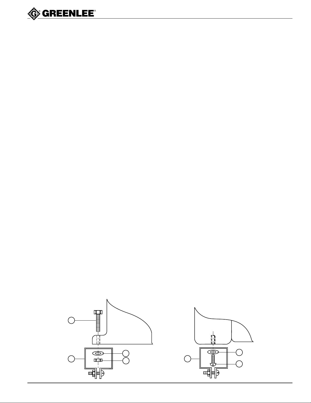
3. After removing the casters from the pump base,
insert the pump mounting hardware; screws, nuts,
and washers (12-15), through the pump base and
pump mounting brackets (6). Loosen clamping
screws on the pump mounting brackets and slide
the brackets attached to the pump, onto the pump
table supports (5). When the pump is in proper
position, tighten the clamping screws on the pump
mounting brackets. Now you may fully tighten all
four of the conduit clamps (8).
4. Attach the 90° coupling (9) to the ram coupling of
the bender, then connect the pump to the ram, using
the high pressure hose supplied with your bender.
Greenlee Textron Inc. / Subsidiary of Textron Inc.
4
4455 Boeing Dr., Rockford, IL 61109-2988 815/397-7070
Page 5
Adjusting Ram Position
(2-1/2" through 4" Conduit)
1813 Bending T able
Changing Ram Positions
Setup
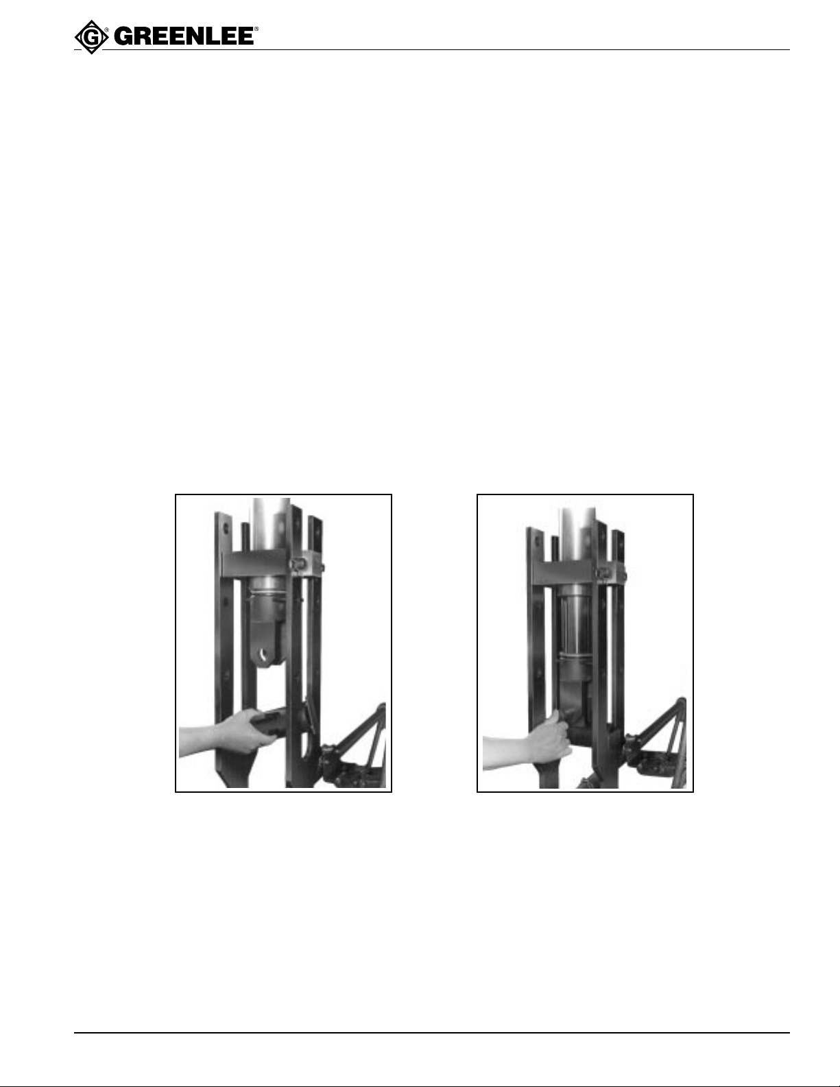
1. The ram positioner (10) is used to adjust the
position of the ram for the size of conduit you are
going to bend. Refer to the markings stamped on
the connecting bars for the proper ram positions for
each size of conduit.
2. Attach the yoke to the ram, using the large spring
clip as shown, in Fig. 5. Then rotate the yoke
90° from its normal position and place the ram
positioner (10) between the connecting bars as
shown in Fig. 1. Mounting tabs of ram positioner
should be up as shown in Fig. 5.
3. Apply pressure to gradually extend the ram until the
holes of the ram positioner line up with the holes of
the yoke. Then attach the ram positioner to the yoke
with the yoke pin as shown in Fig. 2.
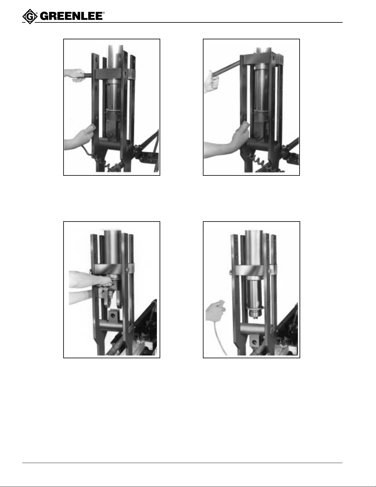
1. Remove the small spring clips from each of the
cylinder head pins and then remove each pin as
shown in Fig. 3. You may need to apply or release
pressure on the ram in order to free the pins from
the cylinder block.
2. Use the pump to extend the ram if you wish to raise
the cylinder block—or release the pressure to lower
the block—to align it with proper set of holes in the
connecting bars for the size of conduit you are
bending. Again you may need to apply or release
pressure in short bursts in order to properly align
the holes before you can re-insert the cylinder head
pins as shown in Fig. 4.
Note: Be very careful that you do not elevate the ram
unit above the top of the connecting bars when
positioning for 4" conduit.
Figure 1 Figure 2
Greenlee Textron Inc. / Subsidiary of Textron Inc.
5
4455 Boeing Dr., Rockford, IL 61109-2988 815/379-7070
Page 6
1813 Bending T able
Figure 3
Figure 4
Figure 5
Greenlee Textron Inc. / Subsidiary of Textron Inc.
Figure 6
6
4455 Boeing Dr., Rockford, IL 61109-2988 815/397-7070
Page 7
Bending
1813 Bending T able
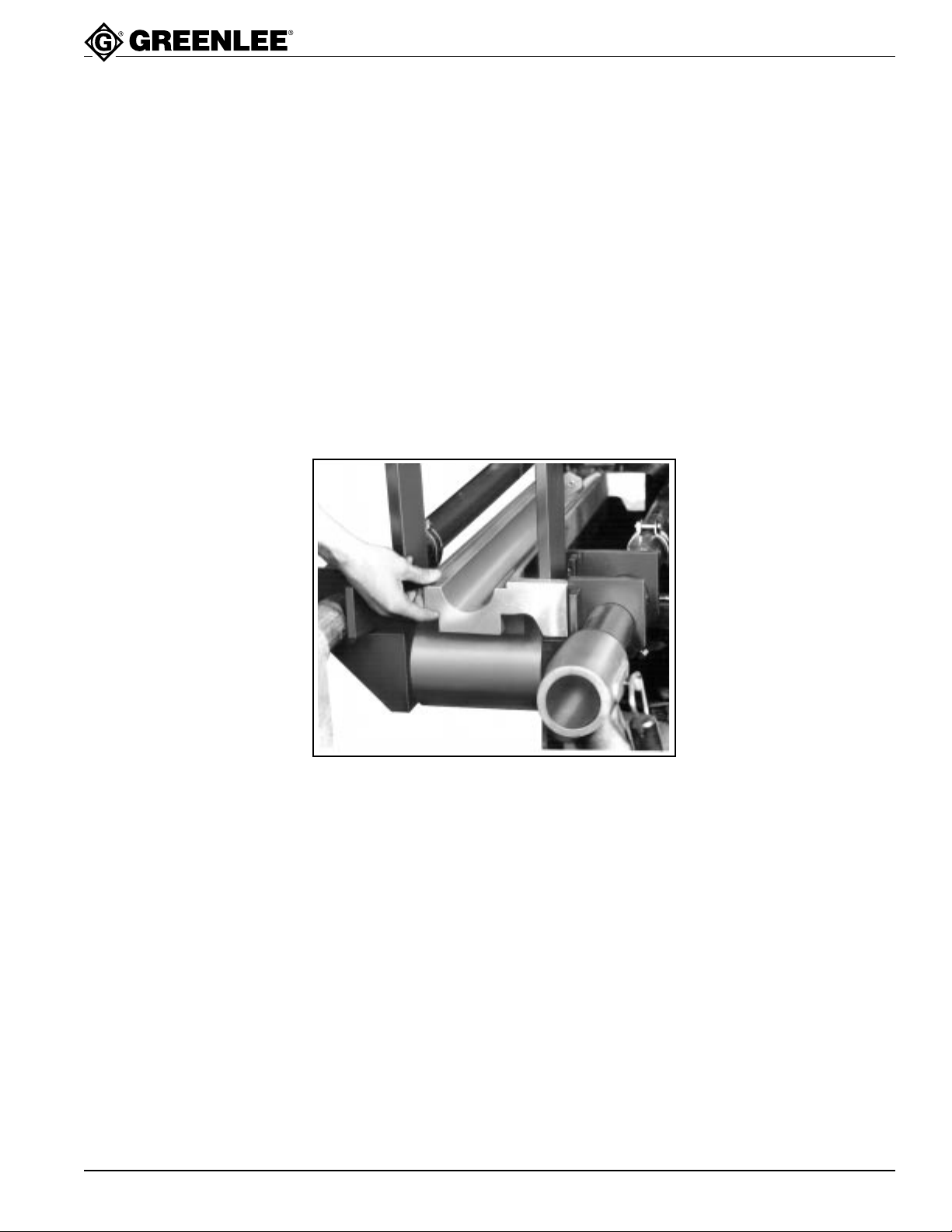
1. Install the proper shoe and follow bar for the conduit
size to be bent. To make sure the follow bar is
properly centered between the connecting bars,
push the foot of the follow bar against one of the
locating guides on the side of the bender mounting
unit (4) as shown in Fig. 7. Do not allow the follow
bar to make contact with either of the bender
connecting bars.
2. Load the conduit into the bender and position for
the required bend. Attach the saddle to the shoe,
being sure to align the bending mark with the front
of the saddle.
3. Attach the Greenlee No. 1805 Bending Degree
Protractor (11) to the portion of the conduit projecting in front of the saddle. Be certain the protractor is
properly zeroed before you start each bend.
4. Strap down the other end of the conduit, using the
chain vise on the pipe vise assembly (3). Always
locate this assembly as close as possible to the end
of the conduit being bent. When bending short
lengths of conduit, be very careful to maintain
enough distance between the pipe vise assembly
and the pump support units (5). DO NOT ALLOW
THESE UNITS TO MAKE CONTACT DURING A
BEND.
5. Now make the desired bend, referring to the bending degree protractor (11) as you do so.
Note: Pipe vise assembly is designed to allow only a
1° maximum variation between bends of various
conduit sizes from 2-1/2 to 4".
Greenlee Textron Inc. / Subsidiary of Textron Inc.
Figure 7
7
4455 Boeing Dr., Rockford, IL 61109-2988 815/379-7070
Page 8
1813 Bending Table
9
11
10
8
4
5
22
(4)
1
2
7
21
(3)
20
(3)
19
(2)
18
(2)
17
(6)
15
(4)
22
(4)
14
(3)
13
12
(2)
16
A
3
1813 Bending T able
Greenlee Textron Inc. / Subsidiary of Textron Inc.
8
4455 Boeing Dr., Rockford, IL 61109-2988 815/397-7070
Page 9
Parts List
KEY PART NO. DESCRIPTION QTY
10 502 9022.3 Positioner, Ram Unit ...........................................................................1
11 502 1318.0 No. 1805 Bending Degree Protractor.................................................. 1
12 905 2471.3 Screw, Cap 1/2–13 x 3.25" Hex Hd. ................................................... 2
13 905 0544.1 Screw, Cap 1/2–13 x 1.50" Hex Hd. ................................................... 1
14 905 1510.2 Washer, Flat .531" x 1.06" x .093" ......................................................3
15 905 2610.4 Nut, Hex 5/8–11 Lock Hd. Thin ........................................................... 4
16 502 8893.8 Carriage Unit .......................................................................................1
17 905 1788.1 Screw, Shoulder .750" x 2.75" x 5/8–11 ............................................. 6
18 502 4720.4 Roller .767" x 2.50" x 2.12" 2" Pipe (1813) ........................................ 2
19 502 1351.2 Spacer .824" x 1.05" x .38" .................................................................2
20 905 0507.7 Washer, Lock .516" x .871" x .099" Spr. .............................................3
21 905 2794.1 Nut, Hex 1/2–13 Zinc Plated ............................................................... 3
22 502 4765.4 Roller .767" x 1.50" x 2.68 Str. (1802) ................................................ 4
1813 Bending T able
1 502 1345.8 Leg Support ......................................................................................... 2
2 905 1787.3 Cap Screw, 1/2–13 UNC x 1" Hex Hd. Cap ...................................... 12
3 502 8900.4 Vise Unit, Pipe (Includes Keys 12-22 and A)...................................... 1
4 502 8885.7 Bender Mount Unit .............................................................................. 1
5 502 9004.5 Support, Pump Table .......................................................................... 2
6 905 3824.2 Bracket, Pump Mounting .....................................................................4
7 502 1346.6 Leg....................................................................................................... 4
8 905 3014.4 Clamp, Steel Conduit .......................................................................... 4
9 502 9014.2 Coupling, Fitting Unit ...........................................................................1
502 3274.6 Storage Box (Not Shown)
A 502 7994.7 Vise Unit, Bench .................................................................................. 1
502 7316.7 Table, Bench Vise ...............................................................................1
905 0638.3 Nut 5/16" Hexagon Steel Regular full .................................................2
905 3160.4 Pin, 3/8" x 1 3/4" Type-C Driv-Lok ......................................................1
502 4985.1 Roller ...................................................................................................1
502 4987.8 Spacer .................................................................................................1
502 5550.9 Handle Unit, Vise................................................................................. 1
905 0420.8 Rollpin, 1/8" x 1.00", No. 59-028-125-1000 ........................................1
502 5553.3 Screw, Chain ....................................................................................... 1
502 6430.3 Pin, Chain ............................................................................................ 1
502 9003.7 Jaw, Vise .............................................................................................4
502 4971.1 Chain, Vise .......................................................................................... 1
905 1166.2 Screw, 5/16–18 NC x 2" Long SAE Grade 5, Hexagon Head Cap .... 2
Mounting Hardware for 975/980 Pumps
12 905 1185.9 Screw, 1/4-20 UNC x 1/2 Rd. Hd. Slotted Mach................................. 4
14 905 0504.2 Washer, 1/4 Lock ................................................................................ 4
Mounting Hardware for 960 Pumps
13 905 0975.7 Screw, 1/4-20 UNC x 1" Long Hex Hd. Mach. .................................... 4
14 905 1674.5 Washer, 1/4 Lock ................................................................................ 4
15 905 1593.5 Nut, 1/4-20 UNC Hex .......................................................................... 4
24
960 RESERVOIR
975/980
RESERVOIR
6
Greenlee Textron Inc. / Subsidiary of Textron Inc.
25
26
25
6
9
4455 Boeing Dr., Rockford, IL 61109-2988 815/379-7070
23
Page 10

GREENLEE
Greenlee Textron Inc. / Subsidiary of Textron Inc.
4455 Boeing Drive, Rockford, IL 61109-2988 USA
General Offices: 815/397-7070
Customer Center and Field Service: 800/435-0786
Fax (24 Hour) Customer Center: 800/451-2632 • 815/397-1865
Canada Fax (24 Hour) Customer Center: 800/524-2853
Printed in U.S.A.
 Loading...