

Page 1
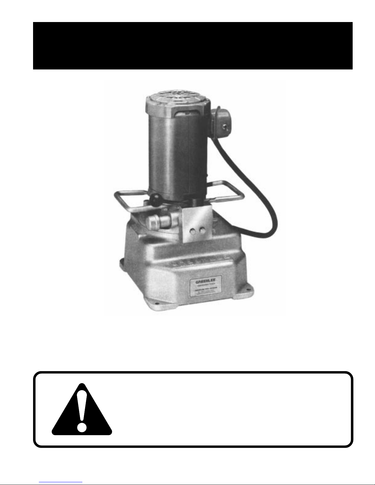
Shown with
OPERATION, SERVICE AND PARTS
INSTRUCTION MANUAL
Optional
Control Valve
1721-M4 & 1722-M4 BASIC
Patent No.
3,389,660
HYDRAULIC POWER PUMP
Read and understand this material before operating
or servicing this power pump. Failure to understand
999 6430.9 © 1997 Greenlee Textron IM 836 REV 6 7/97
how to safely operate this pump could result in an
accident causing serious injury or death.
Page 2
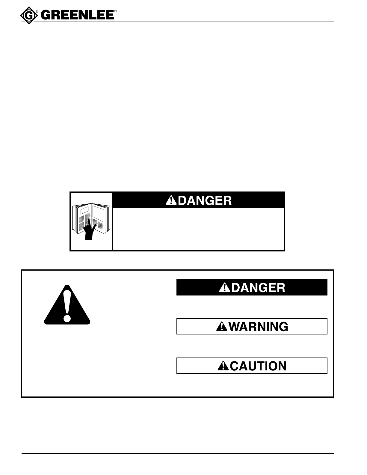
Table of Contents
1721-M4 Basic & 1722-M4 Basic Hydraulic Power Pumps
Safety Information ....................................................................2-3
Introduction .................................................................................4
Assembly.....................................................................................4
Motor ...........................................................................................4
Operation ....................................................................................5
Service ........................................................................................5
Motor Maintenance .....................................................................5
Troubleshooting Chart (Minor Hydraulic Problems) ...................6
Pump Specifications....................................................................6
Parts and Parts List................................................................8-10
A person who has not read and does not understand all
operating instructions is not qualified to operate this tool.
Failure to read and understand safety instructions may
result in injury or death.
SAFETY
ALERT
SYMBOL
The symbol above is used to call your attention
to instructions concerning your personal safety.
Watch for this symbol. It points out important safety
precautions. It means “ATTENTION! Become alert!
Your personal safety is involved!” Read the
message that follows and be alert to the possibility
of personal injury or death.
Immediate hazards which, if not avoided, WILL result in
severe personal injury or death.
Hazards or unsafe practices which, if not avoided, COULD
result in severe personal injury or death.
Hazards or unsafe practices which, if not avoided, COULD
result in minor personal injury or property damage.
Greenlee Textron / Subsidiary of Textron Inc.
2
4455 Boeing Dr., Rockford, IL 61109-2988 815/397-7070
Page 3
1721-M4 Basic & 1722-M4 Basic Hydraulic Power Pumps
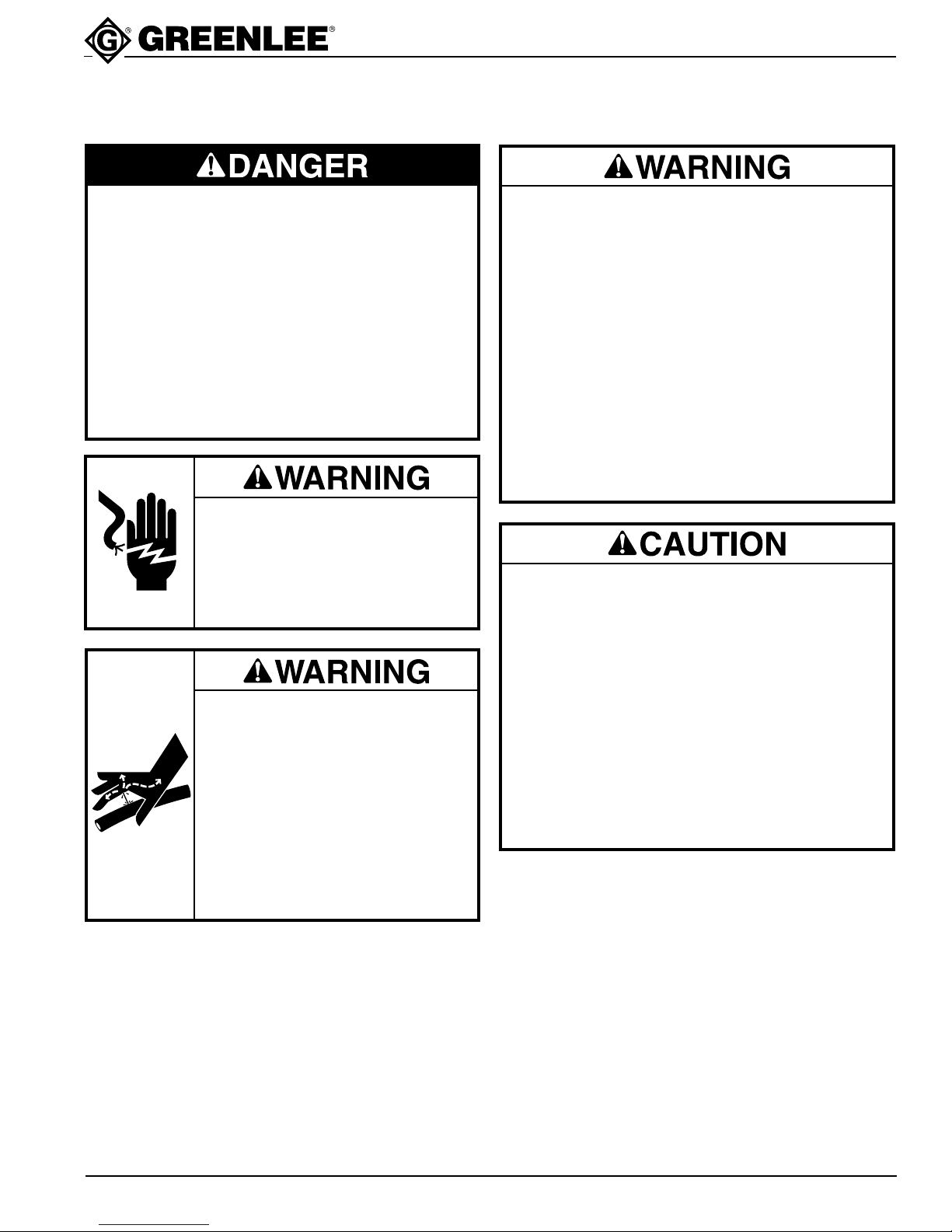
IMPORTANT SAFETY INSTRUCTIONS
• Do not connect the pump to any system or
system component other than those supplied by
Greenlee and rated at less than 10,000 psi
(68,950 kPa).
• Do not alter the internal high-pressure relief valve
setting.
• Do not use this pump in a hazardous environment. Hazards include open flame and flammable
liquids or gases.
Failure to observe these warnings could result in
severe injury or death.
Electric Shock Hazard:
• Do not expose power tools to
rain.
• Do not immerse the pendant
switch in water or other liquid.
Skin Injection Hazard:
High pressure oil easily punctures
skin, causing serious injury,
gangrene or death. If injured, seek
medical help immediately to remove
oil.
Do not use fingers or hands to
check for leaks.
Depressurize hydraulic system
before disconnecting the hose.
• Inspect pump, hoses, couplers and fittings for
wear or damage. Replace worn, damaged or
missing components with Greenlee replacement
parts.
• Do not twist, kink, curl, paint or cut the hydraulic
hoses.
• Wear eye protection when operating this
equipment.
• Disconnect the pump from the power supply,
rotate the release valve lever to AUTO RELEASE
position, and disconnect the hose from the ram
and the pump before performing any service.
Failure to observe these warnings could result in
severe injury or death.
• The pump is heavy, weighting up to 75 lbs.
Follow NIOSH work practices for manual lifting.
If in doubt, get help.
• Unplug pump when not in use and when
changing accessories.
• Do not use the hose to pull, lift, or carry the
equipment.
• Always work in an area providing good footing
and support.
• Keep work area well-lit, free of clutter, and dry.
Failure to observe these warnings could result in
injury or property damage.
SAFE THESE INSTRUCTIONS
Additional copies of this manual are available upon request at no charge.
Greenlee Textron / Subsidiary of Textron Inc.
3
4455 Boeing Dr., Rockford, IL 61109-2988 815/397-7070
Page 4
1721-M4 Basic & 1722-M4 Basic Hydraulic Power Pumps
Introduction
The 1721-M4 and 1722-M4 hydraulic power pumps are
lightweight, portable, durable, and easy to use. When
used as intended, these pumps should provide years of
trouble-free service.
The 1721-M4 and 1722-M4 pumps have two operating
modes: high volume/low pressure and low volume/
high-pressure. This two-mode operation is a time-saving
feature that allows fast ram approach and an automatic
switchover when pressure exceeds 200 psi.
The pumping unit is a single-piston radial-type capable
of developing 10,000 psi. An integral unloading check
valve unloads the high-pressure stage of the pump and
permits the motor to be restarted while maintaining the
load. These models have an externally mounted adjustable relief valve for quick and easy adjustment of maximum pressure. The pumping unit is protected by a safety
valve set at 10,000 psi.
When setting the external adjustable relief valve,
do not set the pressure over the safety valve
setting or 10,000 psi.
Assembly
The 1721-M4 and 1722-M4 pumps are completely
assembled and are shipped as a complete pumping unit.
The only assembly necessary is the connection of the
ram to the pump and the power cord to the proper
electrical outlet.
Motor
The 1721-M4 pump is powered by a 1 hp, 1725 rpm,
60-cycle, end-mounted, totally enclosed, fan-cooled,
ball bearing, dual-voltage electric motor. If 230 volt AC
operation is required and the pump has not been wired
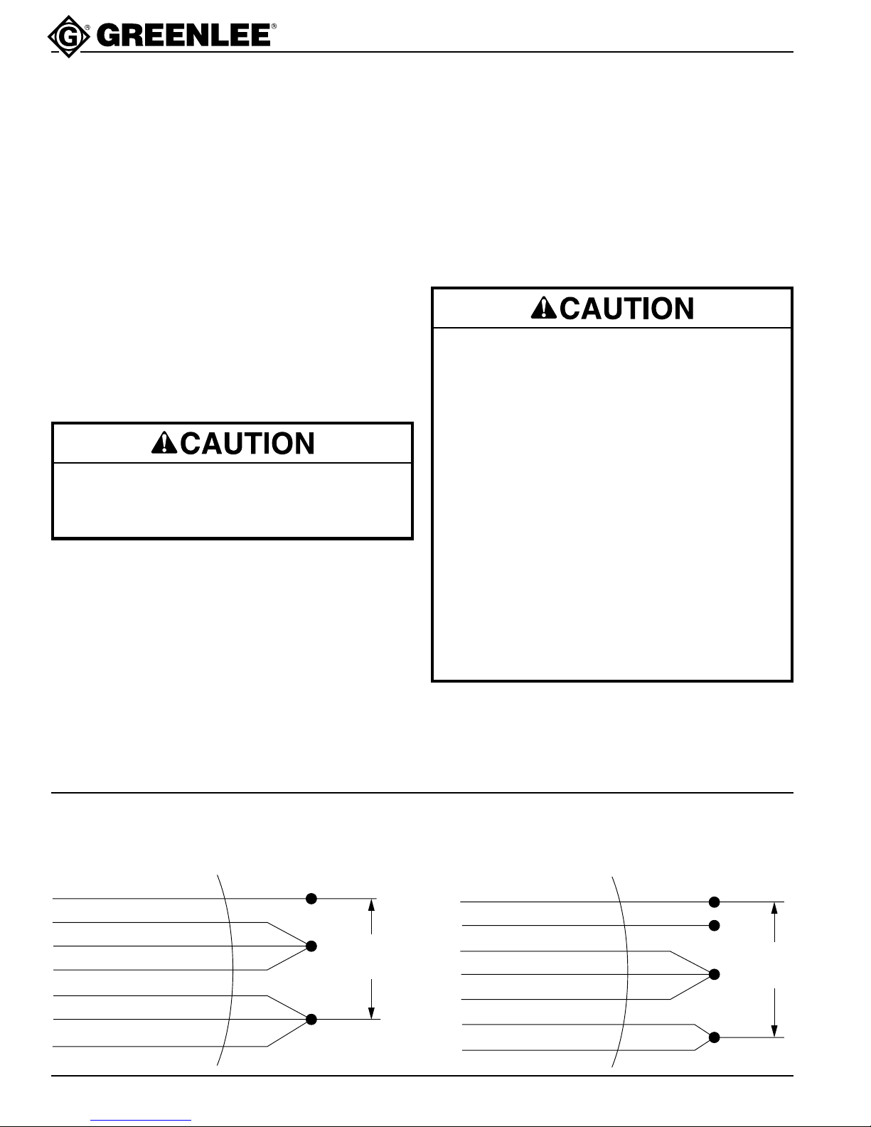
at the factory for 230 volt AC, the motor leads must be
rewired in accordance with the wiring diagram shown.
The 1722-M4 power pump is identical to the 1721-M4
pump except that it is powered by a 1-1/2 hp, 3600 rpm
motor and delivers twice the volume.
For your protection, ground unit before using.
The electric motor is equipped with an approved
3-conductor cord and 3-blade grounding-type
attachment plug to be used with the proper
grounding-type receptacle, in accordance with the
National Electrical Code. The green-colored
conductor in the cord is the grounding wire, which
is attached to the metal frame of the unit inside
the housing and to the longest blade of the
attachment plug cap. A special grounding adapter
is supplied (except in Canada or for use above
150 volts) to permit using two-wire receptacles
until the correct receptacle is installed. The green
grounding wire extending from the side of the
adapter must be connected to a permanent
ground such as a properly grounded outlet box,
conduit or water pipe, before plugging in the unit.
Use only extension cords that are sufficiently rated
and a properly connected grounding circuit.
Motor Wiring Diagram
CONNECTIONS FOR CW ROTATION (VIEW MOTOR FROM LEAD END)
Franklin GE
Brown (10)
Violet (9)
Pink (1)
Orange (5)
Black (2)
Red (8)
Blue (4)
Greenlee Textron / Subsidiary of Textron Inc.
Purple P1
Brown P2
Black T5
Orange T3
Yellow T4
Red J10
White T2
LOW VOLTAGE
Low
Voltage
Line
Franklin GE
Brown (10)
Violet (9)
Pink (1)
Orange (5)
Blue (4)
Red (8)
Black (2)
4
HIGH VOLTAGE
Purple P1
Brown P2
Black T5
Orange T3
White T2
Red J10
Yellow T4
4455 Boeing Dr., Rockford, IL 61109-2988 815/397-7070
Insulate This Lead
High
Voltage
Line
Page 5
Operation
1721-M4 Basic & 1722-M4 Basic Hydraulic Power Pumps
The pump is designed to operate at 10,000 psi. For
continuous service, such as production work, the
pressure intermittently, should not exceed 6,000 psi.
This limitation is for the protection of the motor only.
Before operating the pump, check the following procedures to assure proper service:
1. Check proper power connections and tightness of
hose connections before starting pump.
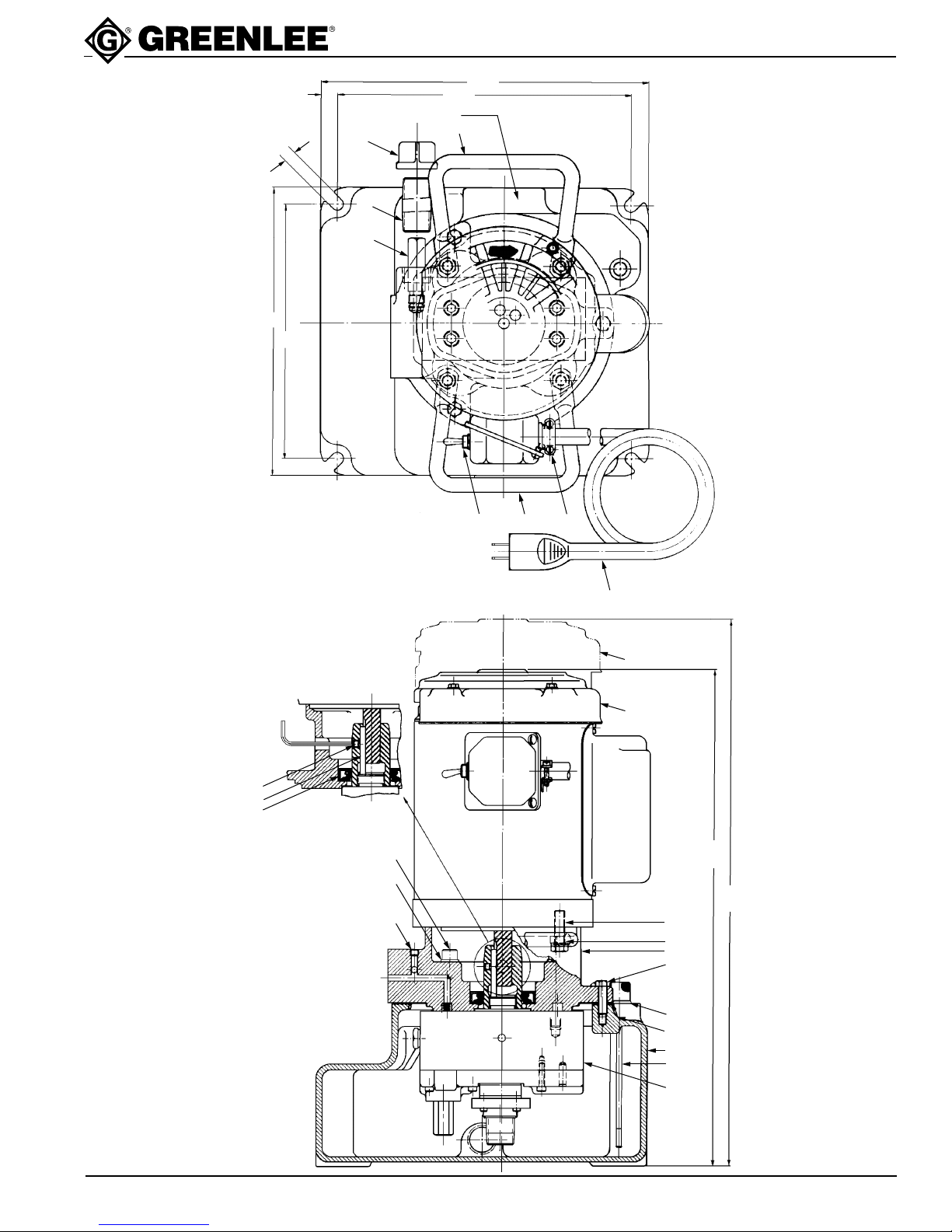
2. Check hydraulic oil with dip stick (53). Oil should be
within 1/2” of reservoir top.
3. Start motor and allow pump to idle a few minutes.
This will allow the hydraulic oil to work into moving
parts and give prime to pump.
Service
Filling the Oil Reservoir
In order for the pump to operate properly, the oil
reservoir must be kept filled with a good grade of light
hydraulic oil: Greenlee 905 0806.8 hydraulic oil or
equivalent. Eight quarts are required, of which 6-1/4
quarts are usable. A minimum of 1-3/4 quarts must be
at the bottom of the reservoir at all times during the
operation. Be sure that the complete operation does not
require more than the usable amount of oil.
Flushing the System
As long as the pump is used as outlined in the operating
instructions, trouble-free performance can be expected.
To maintain this performance, it is absolutely essential
that dirt or other foreign matter be kept out of the system, as this is the most common cause of hydraulic
system failure. When opening the pump for any reason,
such as making pipe connections, adjusting pressure or
any repair, exercise extreme care in cleanliness and use
clean tools and cloths. If at any time dirt is suspected to
have entered the system, the entire oil system should be
flushed as follows:
1. Drain oil from reservoir.
2. Fill reservoir with any recommended flushing oil or
clean kerosene and operate pump. Work the control
handle back and forth several times during flushing
to wash all foreign particles from the control valve
unit.
Do not operate pump for long periods of time. The
system is not designed to operate with flushing oil
or kerosene.
Do not use synthetic fluids with poor lubricating
qualities such as brake fluids. The result is permanent damage to the pump.
To refill or add oil to the reservoir, proceed as follows:
1. Remove vent unit from top of reservoir.
2. Add oil to within 1/2" of top of reservoir when ram is
retracted.
3. Install vent unit securely.
Before operating pump, be sure vent unit is not
clogged.
3. Drain flushing oil or kerosene from reservoir and
refill with new oil.
Motor Maintenance
Greenlee recommends the 1721-M4 and 1722-M4 be
sent to a qualified Greenlee Service Center or to the
manufacturer when in need of repair.
Greenlee Textron / Subsidiary of Textron Inc.
5
4455 Boeing Dr., Rockford, IL 61109-2988 815/397-7070
Page 6
1721-M4 Basic & 1722-M4 Basic Hydraulic Power Pumps
Troubleshooting
Observe the hydraulic unit constantly for out-of-the-ordinary performance and unusual noises. If any of these are
present, shut off pump and take corrective steps immediately, to avoid possible expensive repairs. Minor problems
and their remedies are listed in the following chart.
PROBLEM PROBABLE CAUSE POSSIBLE REMEDY
Pump motor will not start. Power cord not sufficiently Check for tight connections.
connected.
Power cord cut. Replace power cord.
Defective motor or switch. Replace or repair.
Fuse in wall box is blown. Replace fuse.
Will not pump oil. Not primed. Run pump for a few minutes, tipping
unit from side to side.
Sticking plunger. Replace plunger & bushing (8 & 9).
Plugged-up screens. Clean or replace intake screen (24).
Defective control valve. Repair or replace.
Sticking vanes. Repair or replace vane (16) and
rotor (17).
Excessive noise in Low in oil. Add oil.
hydraulic system.
Air in system. Run pump to work out air.
Loose drive shaft adapter. Tighten set screw (68).
Defective motor. Replace.
Necessary to add oil often. Oil leaks. Check for broken lines, loose fittings
or connections.
It is recommended that the pump be sent to a qualified service station or the manufacturer if the preceding remedies
fail to make the pump function properly. Do not allow unqualified personnel to attempt to repair the pump, the pump
block or control valve unit, as irreparable damage may result.
Pump Specifications
Pump Control Control Power Source Cu./Min. Height Base Reservoir Oil Vol. Wt.
Model No. Valve Type HP Volts 100 psi 10,0000 psi Capacity Qt.
1721-M4
Basic
1722-M4
Basic
Greenlee Textron / Subsidiary of Textron Inc.
501 8320.6 Optional AC 1 (15 min.) 115/230 150 30 20-3/4 10-1/2 x 12 8 6-1/4 99
501 8355.9 Optional AC 1-1/2 (15 min.) 115/230 300 60 20-3/4 10-1/2 x 12 8 6-1/4 104
Pumping Capacity Usable
6
4455 Boeing Dr., Rockford, IL 61109-2988 815/397-7070
Page 7
1721-M4 Basic & 1722-M4 Basic Hydraulic Power Pumps
.43
10.50
9.25
.62
SERIAL NO. LOCATION
60
61
52
10.75
56
12.00
73
56 69
1/8 ALLEN WRENCH
68
57
59
NOTE: REMOVE SET SCREW
BEFORE REMOVING
MOTOR.
72
75
74
70
62
67
18.21
1721 SERIES
64
62
54
63
65
58
55
53
A
19.93
1722 SERIES
Greenlee Textron / Subsidiary of Textron Inc.
7
4455 Boeing Dr., Rockford, IL 61109-2988 815/397-7070
Page 8

Parts
1721-M4 Basic & 1722-M4 Basic Hydraulic Power Pumps
22
37
26
22
8
9
33
26
29
1
SECTION B-B
41
7
13
21
20
4
25
19
40
2
.096
.106
70
62
14
11
58
16
17
40
39
36
23
38
28
12
20
6
24A
343
4
32
5
SECTION A-A
2
10A
B
A
A
27
15
18
24
10
30
35
B
Greenlee Textron / Subsidiary of Textron Inc.
8
4455 Boeing Dr., Rockford, IL 61109-2988 815/397-7070
Page 9

1721-M4 Basic & 1722-M4 Basic Hydraulic Power Pumps
Parts - Hydraulic P ower Pumps
1721-M4 Basic (501 8320.6)
1722-M4 Basic (501 8355.9)
Key Control No. Description Qty
A 501 8236.6 Block Unit, Pump (1 - 41) ...................................................................... 1
1 500 6067.8 Valve Unit, Relief ................................................................................... 1
2 501 7766.4 Valve Unit, Relief ................................................................................... 1
3 501 8194.7 Plate, Pump Mounting ........................................................................... 1
4 500 3493.6 Pin, Seal ................................................................................................ 1
5 501 8871.2 Spacer, Bearing ..................................................................................... 1
6 501 1855.2 Race, Outer ........................................................................................... 1
7 501 1862.5 Plug, Hi-Pressure Plunger ..................................................................... 1
8 501 9060.1 Plunger, Hi-Pressure ............................................................................. 1
9 501 9059.8 Bushing, Hi-Pressure Plunger ............................................................... 1
10 502 0424.6 Block, Intake .......................................................................................... 1
10A 501 4859.1 Block, Intake (replaced by 10) ............................................................... 1
11 501 4861.3 Plate, Pump ........................................................................................... 1
12 501 4862.1 Key, Lo-Pressure Pump ........................................................................ 1
13 501 4876.1 Shaft, Eccentric...................................................................................... 1
14 501 7130.5 Plate, Top .............................................................................................. 1
15 501 7131.3 Plate, Bottom ......................................................................................... 1
16 501 7135.6 Vane....................................................................................................... 4
17 501 7136.4 Rotor ...................................................................................................... 1
18 501 7467.3 Dowel, Hollow ........................................................................................ 1
19 501 8195.5 Plunger, Check Valve ............................................................................ 1
20 501 8237.4 Block, Pump........................................................................................... 1
21 501 8238.2 Adapter, Drive Shaft .............................................................................. 1
22 500 6111.9 Spring, Compression ............................................................................. 1
23 501 4865.6 Spring, Compression ............................................................................. 1
24 502 1175.7 Screen, Intake........................................................................................ 1
24A 501 6599.2 Screen, Intake (replaced by 24) ............................................................ 1
25 905 0014.8 O-Ring, 5/8 x 3/4 x 1/16......................................................................... 1
26 905 0436.4 Ball, 9/32 Grade #1 Chrome Steel ........................................................ 2
27 905 0490.9 Nipple, Intake (replaced by 10) ............................................................. 1
28 905 0677.4 Ball, 5/32 Grade #1 Chrome Steel ........................................................ 1
29 905 0681.2 Ball, 3/8 Grade #1 Chrome Steel .......................................................... 1
30 905 1526.9 Washer, #8 Hi-Collar Lock..................................................................... 4
32 905 0911.0 Roller, .125 x .750 ............................................................................... 30
33 905 1524.2 O-Ring, 1/2 x 5/8 x 1/16......................................................................... 1
34 905 0989.7 Bearing, Single Row Unshielded Ball .................................................... 1
35 905 0994.3 Screw, #8-32 NF x 1-1/4 Socket Head Cap .......................................... 4
36 905 1111.5 Screw, 7/16-20 NF x 1/2 Cup Point Socket Set .................................... 1
37 905 2817.4 O-Ring, 7/16 x 9/16 x 1/16..................................................................... 1
38 905 1241.3 Screw, #10-32 NF x 3/16 Flat Point Socket Set .................................... 1
39 905 1471.8 Screw, #10-32 NF x 7/8 Socket Head Set Cap ..................................... 6
40 905 1472.6 Lok-Dowel, 1/4 x 3/4 .............................................................................. 2
41 905 1473.4 Bearing, Single Row Unshielded Ball .................................................... 1
52 500 3407.3 Valve Unit, Relief ................................................................................... 1
53 501 5646.2 Dipstick Unit ........................................................................................... 1
54 503 2705.4 Plate, Motor Mounting ........................................................................... 1
55 501 5695.0 Reservoir ............................................................................................... 1
56 501 2663.6 Handle, Lifting ........................................................................................ 2
57 501 4852.4 Key ......................................................................................................... 1
58 501 5701.9 Gasket Reservoir ................................................................................... 1
59 905 0320.1 Seal, 1-3/8 ID x 2-3/8 OD Oil................................................................. 1
60 905 0467.4 Cap, 3/4 Pipe ......................................................................................... 1
Greenlee Textron / Subsidiary of Textron Inc.
9
4455 Boeing Dr., Rockford, IL 61109-2988 815/397-7070
Page 10
Parts - Hydraulic P ower Pumps (cont’d)
1721-M4 Basic (501 8320.6)
1722-M4 Basic (501 8355.9)
Key Control No. Description Qty
61 905 4091.7 Nipple, 3/4 x 2 Pipe ............................................................................... 1
62 905 0506.9 Washer, 3/8 Lock ................................................................................... 8
63 905 0522.0 Screw, 5/16-18 NC x 1 Hex Head Cap.................................................. 3
64 905 0532.8 Screw, 3/8-16 NC x 1-1/4" Hex Head Cap ............................................ 4
65 905 0387.2 O-Ring, 7/16 x 5/8 x 3/32....................................................................... 1
67 905 0824.6 Plug, 1/16 NPT Socket Head Pipe ........................................................ 1
68 905 1269.3 Screw, 1/4-20 NC x 1/4 Cup Point Socket Head Set ............................ 1
69 918 5117.3 Connector .............................................................................................. 1
70 905 1474.2 Screw, 3/8-24 NF x 2-1/2 Socket Head Cap ......................................... 4
72 918 5264.1 Cord, 10 Foot ......................................................................................... 1
73 918 5284.6 Switch, Toggle ....................................................................................... 1
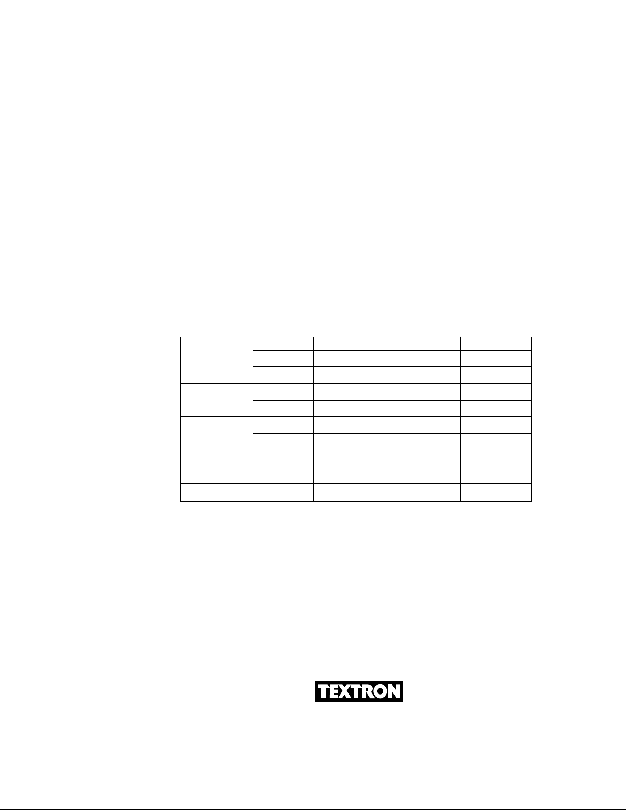
74 918 5183.1 Motor, 1 HP Electric............................................................................... 1
GE Motor 5KC43PG782T
Franklin Motor 1112050101
Dayton 6K674
Service Parts
GE FRANKLIN DAYTON
Greenlee # 918 5349.4 918 6518.2 918 6039.3
Capacitor
Capacitor Cover
Fan
Fan Cover
Shaft Key
Manufctr # 8753704AX16 275463-102 3R 505
Greenlee # 918 5353.2 918 6519.0 918 6040.7
Manufctr # 11B276AAP1 2903312-101 2R831
Greenlee # 918 5389.3 — —
Manufctr # 114A882AAG1 — —
Greenlee # 918 5361.3 — 918 6041.5
Manufctr # 114C922AAP1 — 2R901
Greenlee # 501 4852.4 501 4852.4 501 4852.4
75 918 5466.0 Motor, 1-1/2 HP 3450 RPM (1722-M4 Series Only).............................. 1
GREENLEE
Greenlee Textron / Subsidiary of Textron Inc.
4455 Boeing Drive, Rockford, IL 61109-2988 USA
Customer Center and Field Service: 800/435-0786
Fax (24 Hour) Customer Center: 800/451-2632 • 815/397-1865
Canada Fax (24 Hour) Customer Center: 800/524-2853
General Offices: 815/397-7070
Printed in U.S.A.
 Loading...