

Page 1
Cleaning
Cleaning the Output Port
Cleaning all connectors before coupling them to the 170XL visual fault
finder will ensure proper maintenance of the output port and laser lens.
Users should always cover the output port with the dust cap when the
instrument is not in use.
If binding or stickiness is felt when inserting connectors into the output
port, the ceramic sleeve should be cleaned. To clean the sleeve, insert a
Tempo 946 cleaning wand into the output port until it stops. Twist the
wand, remove it, and discard. Do not reuse the cleaning wand.
Cleaning the Laser Lens
If the intensity of the light output decreases considerably, despite the
batteries being in good condition, the laser lens is probably dirty. Loose
dirt can be removed by applying suction to the output port.
NOTE: Do not blow air into the output port to remove dirt particles. Doing
so will only pack the dirt and make it harder to remove.
If the lens is extremely dirty, flush out the output port with a
small amount of reagent-grade isopropyl alcohol, then apply
gentle suction to remove any remaining dirt. Make sure that all
residual alcohol has evaporated before resuming testing.
Specifications
Light source 635nm red laser diode and monitor,
with multi-quantum well structure
Central wavelength:
Nominal 635nm
Range (typical) 630nm to 640nm
Spectral width < 2nm
Peak power output
1, 2, 3:
Into SMF-28 fiber, CW or 1.0mW (0dBm) maximum
MOD output mode 316µW (-5dBm) minimum
Maximum emitted power 2.0mW
MOD output frequency < 3Hz, approximate
Power requirements Two (2) 1.5V alkaline batteries
Battery life Approx. 48 hrs. continuous operation
Connector interface 2.5mm “quick connect” port
2,
or 16-series SOC adapters
CDRH Class IIIa
Environmental:
Operating temperature -10°C to +50°C
Storage temperature -40°C to +60°C
Humidity 0 to 95% RH, non-condensing
Weight and dimensions 22.9 x 2.54cm (9 x 1 in.)
200g (7 oz) with batteries and pouch
1 Within specified ambient environment of +20°C to +25°C.
2 APC-type ferrule coupling efficiency reduced by > -3dBm.
3 Output power with beam collimator may exceed 1mW. Product complies with CDRH Class II, 1mW
max. without collimator accessory and IEC 825-1: 1993, 5mW max.
EC Declaration of Conformity
We, Greenlee Textron Inc.
4455 Boeing Drive
Rockford, IL 61109-2988
U.S.A
declare under sole responsibility that the 170XL visual fault finder laser
source, manufactured in the United States of America, meets the intent
of the directive 89/336/EEC for electromagnetic compatibility. Compliance
was demonstrated to the following specifications as listed in the official
Journal of the European Communities:
EN 50081-1, Emissions: EN 55022 Radiated, Class B
EN 55022 Conducted, Class B
EN 60555-2 Power Harmonics
EN 50082-1, Immunity: IEC 801-2 Electrostatic Discharge
IEC 801-3 RF Radiated
IEC 801-4 Fast Transients
IEC 801-5 Surge
Warranty Information
Greenlee warrants this product to be free from defects in material and
workmanship for a period of one (1) year from the date of shipment.
During the warranty period we will, at our option, either repair or
replace any product that proves to be defective. To exercise this warranty,
write or call your local Greenlee representative, or contact Greenlee
directly.
You will be given prompt assistance and return instructions. Send the
instrument, transportation prepaid, to the indicated service facility.
Repairs will be made and the instrument will be returned, transportation
prepaid. Repaired products are warranted for the balance of the original
warranty period, or at least 90 days.
Limitation of Warranty
This warranty does not apply to defects resulting from unauthorized
modification or misuse of any product or part. This warranty is in lieu of all
other warranties, expressed or implied, including any implied warranty of
merchantability or fitness for a particular use. Greenlee shall not be liable
for any indirect, special, or consequential damages.
Notice of Proprietary Rights
The design concepts and engineering details embodied in this manual,
which are the property of Greenlee, are to be maintained in strict
confidence.
No element or detail of this manual is to be spuriously used, nor disclosed
without the express written permission of Greenlee. All rights are reserved.
No part of this publication may be reproduced, stored in a retrieval system,
or transmitted in any form or by any means, electronic, mechanical,
photocopying, recording, or otherwise, without prior written permission
from Greenlee.
COPYRIGHT © 2005 BY GREENLEE
ALL RIGHTS RESERVED. FIRST EDITION 2005
PRINTED IN THE UNITED STATES OF AMERICA
Greenlee Textron Inc.
4455 Boeing Drive
Rockford, IL 61109-2988
U.S.A
www.greenlee.textron.com
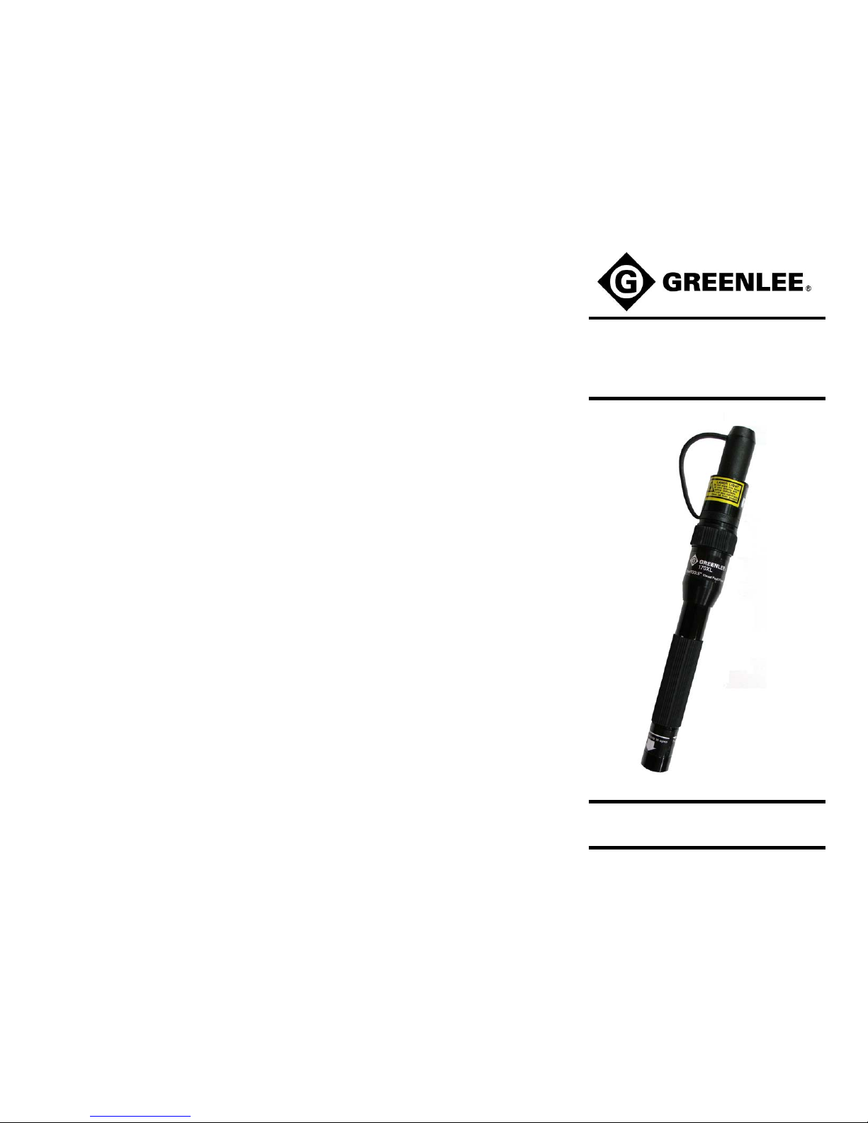
USER MANUAL
170XL
VISUAL FAULT FINDER
97-0170-67 Rev A
Page 2
Product Description
The Greenlee 170XL visual fault finder is a pocket-sized, rugged, and
splash proof handheld instrument incorporating a stabilized, high output
635nm laser diode. Providing up to 48 hours of continuous operation
using two AA-size alkaline batteries, the 170XL can clearly locate breaks
and bending losses in optical fibers up to 3km in length. A rotary switch
on the instrument permits the user to select between continuous wave
(CW) and a blink (MOD) mode that increases viewing contrast, or to
switch the instrument off with one hand. The 170XL is fitted with a
universal “quick connect” output port that enables convenient temporary
coupling with all 2.5mm fiber optic connectors. The instrument can also
be used with optional 16-series Snap-On Connector (SOC) adapters,
which permit secure coupling with industry standard fiber optic interfaces.
In addition, an optional beam collimator adapter permits testing of multipin interfaces, such as Deutsch Ltd. ruggedized connectors, without the
need for disassembly.
Standard Contents
1 170XL visual fault finder
1 Nylon carrying pouch
1 User manual
2 1.5V alkaline batteries
Optional Accessories
16-series Snap-On Connector (SOC) adapters
Beam collimator assembly
946 adapter cleaning wands (for cleaning output port)
Battery Installation/Replacement
The 170XL visual fault finder is shipped without the batteries
installed.
The two AA-size alkaline batteries shipped with the instrument
must be installed before use. Greenlee does not recommend the
use of non-alkaline or rechargeable batteries in the instrument.
NOTE: If the LED indicator appears dim during operation, it is time
to replace the batteries in the unit.
To install or replace the batteries, do the following:
1) Make sure the rotary switch is in the OFF position.
2) Unscrew the end cap by turning it counterclockwise, then remove
the used batteries, if any.
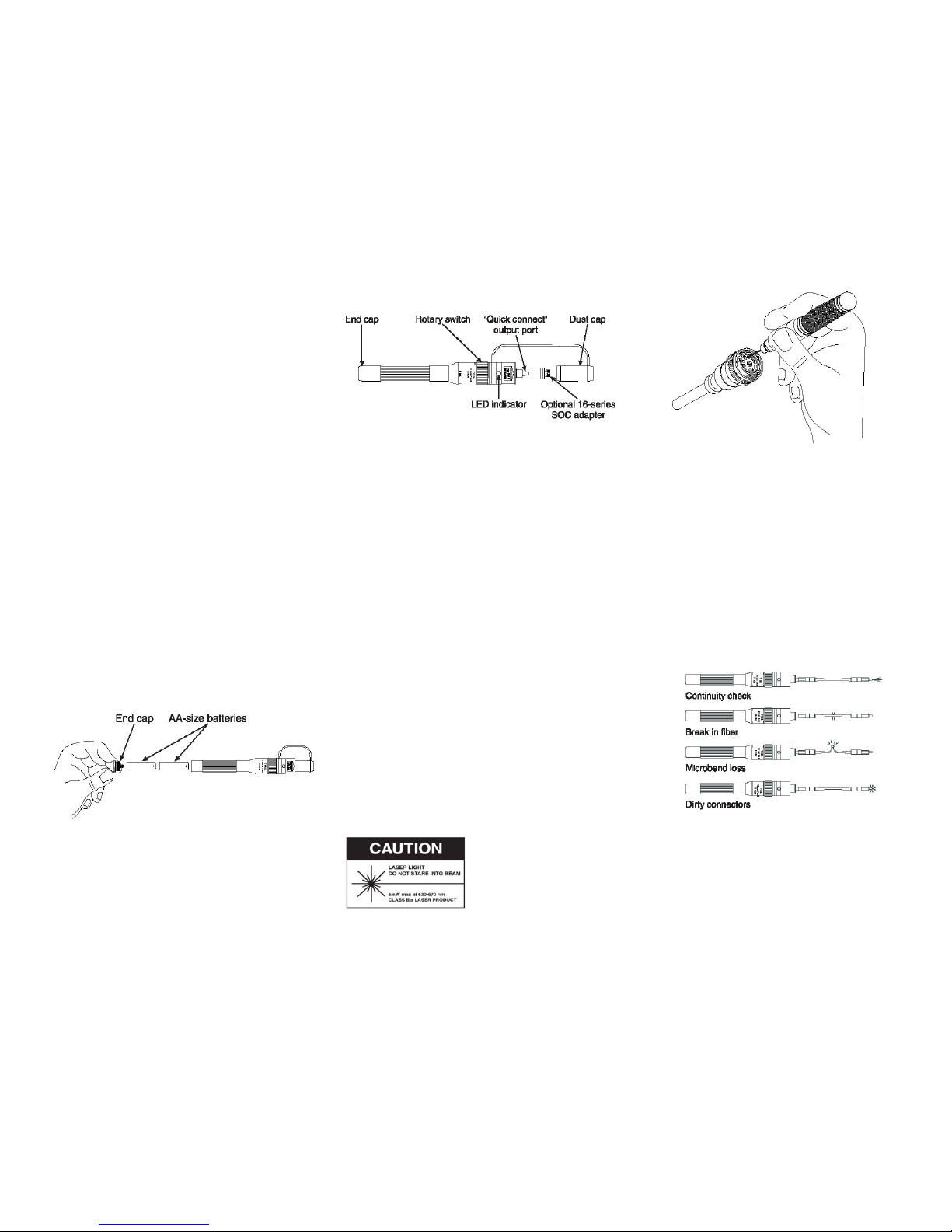
3) Insert two new AA-size alkaline batteries positive end first, as
shown in the above illustration.
4) Replace the end cap, turning it clockwise to tighten it in place.
Operation
Controls and Indicators
Using the 2.5mm “Quick Connect” Output Port
1) Insert the ferrule of a fiber optic connector into the “quick connect”
output port, ensuring that it seats completely. The user should
always clean the end face of the connector before inserting it in the
“quick connect” output port.
2) Rotate the switch to the desired operating mode by moving it to the
right. The first position puts the instrument in continuous wave (CW)
mode. The second position puts the instrument in blink (MOD)
mode. The LED indicator on the unit will illuminate steadily in CW
mode. It will blink in MOD mode.
3) See the Applications section for instructions on tracing faults in
optical fibers.
Using a 16-Series SOC Adapter
Optional 16-series Snap-On Connector (SOC) adapters are available for
FC, SC, ST, and DIN fiber optic connectors. SOC adapters fasten secure
to fiber optic connectors and prevent them from pulling loose from the
instrument. To use a 16-series SOC adapter with the 170XL, do the
following:
1) Select the appropriate 16-series SOC adapter and snap it over the
“quick connect” output port.
2) Insert the connector under test into the adapter and secure it. Most
fiber optic connectors are secured by turning the outer sleeve clock
wise.
3) Rotate the switch to the desired operating mode.
4) See the Applications section for instructions on tracing faults in
optical fibers.
NOTE: 10-series SOC adapters cannot be used on the 170XL
visual fault finder, as they are larger in diameter.
WARNING: Do not look directly into the
output port when the instrument is ON.
Never use a viewing instrument such as
a magnifier or microscope to view the
free end of any optical fiber connected to
the T170XL visual fault finder. The use of
viewing on active fibers can focus an
intense laser beam onto the retina of the
eye, resulting in permanent damage or
blindness.
Always aim the free end of an active
fiber at a non-reflective surface.
Using the Beam Collimator
The optional beam collimator concentrates the laser output from the 170XL
visual fault finder, eliminating the need for a physical connection when
conducting tests. The beam collimator is especially useful when testing
female multi-pin connectors. While the beam collimator can also be used to
test male multi-pin connectors if held steadily in the hand, this may be
impractical in the field. Greenlee recommends using a FoPro™ fiber optic
probe for testing the male end of multi-pin connectors.
CAUTION: Do not stare into the collimated beam, or view it using a
magnifying instrument. The laser output may exceed 1mW when using the
beam collimator.
1) Snap the beam collimator over the “quick connect” output port.
2) Rotate the switch to the desired operating mode.
3) Aim the collimated beam into the receptacle under test.
4) See the Applications section for instructions on tracing faults in
optical fibers.
Applications
The 170XL visual fault finder is designed to quickly locate breaks in optical
fibers. Any interruption in continuity will be indicated by red light escaping
from the fiber. Light can also escape from the fiber if it is stressed or bent
too tightly. In either case, escaping light is a sure sign of a problem.
The 170XL visual fault finder can also be used to check the condition of
ceramic ferrules. A fiber break inside, or past, the ferrule will make it glow. If
the entire connector glows, it is definitely bad.
A glowing ferrule can also indicate a bad end face polish. If the end face
polish is bad, light in the fiber will be reflected internally and be visible through
the ferrule.
 Loading...