

green-i PDS-PRM, PDS-PRM/S Product Manual
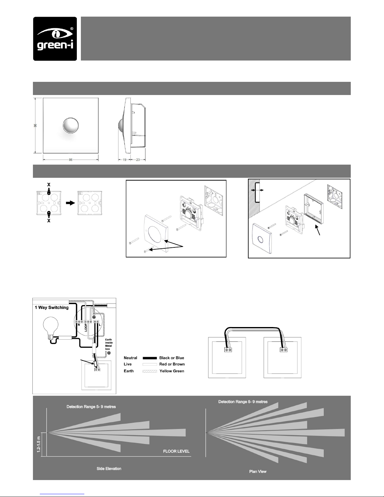
The detector should be sited so that the occupants of the room fall inside the detection pattern shown below, at a recommende d height of 1.2m to
1.5m for wall sensors. Note that the higher the sensor is installed the shorter the detection range will be.
Avoid direct sunlight entering the sensor.
Do not site within 1m of forced air heating or ventilation.
Do not site within 1m of any lighting.
Do not fix to a vibrating surf ace.
Compatible with all BS4662
dimensions back boxes.
Remove top and bottom lugs if
fitted.
< 25mm
Do not overtighten
The PDS-PRM presence detector switches are designed to provide automatic control of
lighting, heating or ventilation loads. They detect movement using a PIR sensor and
turn the load on. W hen an area is no longer occupied the load will switch off after an
adjustable time out period.
An internal light sensor provides additional energy saving in lighting applications. When
an area is occupied lighting is only switched on when the level of natural light is below a
preset level.
A selectable security mode switches the lights on for a period of 2 hours when it gets
dark, regardless of occupancy, to give the impression of a building being occupied.
The PDS-PRM/S comes with longer mounting screws and countersunk holes on the
cover plate. This is to allow the installer to secure the unit and cover plate with external
screw fixings.
1 way switching
If the lights are controlled
from one location only, wire
as in the diagram.
May have red or
brown sleeve
Com L1
2 way switching
If more than one detector is required to switch the lighting (e.g. at
the top and bottom of a staircase) they can be wired in parallel, as
in the diagram.
Com L1 Com L1
Use the extender if there is less than
25mm free space.
REMEMBER—put the wires through
the extender before connecting.
Installation and wiring
Screw fixings for
PDS-PRM/s
No Neutral Wall Mounted PIR Presence Detector
PDS-PRM & PDS-PRM/S
Product Guide
Overview
LOAD DOES NOT COME ON
Check to see if the live supply to the circuit is good. Strap across the L and LIVE OUT terminal to turn the load on.
If the supply and wiring are good, check the LUX level setting. Increase the LUX level setting to allow the controller to tur n on at higher ambient natural
light level.
LIGHTS DO NOT GO OFF
Ensure that the area is left unoccupied for a greater time period than the time out period set using the switch.
Make sure that the sensor is not adjacent to circulating air, heaters or lamps.
PDS-PRM Wall mounted PIR presence detector
PDS-PRM/S Wall mounted PIR presence detector with external screw fixing
Time
Setting
1min 30 min
Lux setting
1. Activate the unit by setting DIL switch 1 on.
2. Allow about 60 seconds for the unit to settle.
3. Set the LUX level thumbwheel fully clockwise, and
the time setting to minimum (fully anticlockwise).
4. Check that the load switches on when movement
is detected, and turns off again about 1 minute
after the area has been vacated.
5. To set the final LUX level wait until the level of
natural daylight is just enough that lighting is required. Starting with the LUX thumbwheel fully anti
-clockwise. Very slowly turn the thumbwheel clockwise until the lights come on. Note that when the
LUX thumbwheel is fully clockwise then the lights
will always come on with occupancy.
6. If required, select the security mode using DIL
switch 2.
7. If the unit is not going to be used for a prolonged
period of time, deactivate by setting DIL switch 1
off. This will preserve battery life.
Battery
Unit deactivated
Security mode
activated
Unit activated
Security mode can be turned on and off using the switches as
shown in the “setup” section.
When activated, security mode is used to switch on lighting when it
gets dark, giving the impression a house is occupied.
When the unit senses that the outside light is dark, the lights will
automatically switch on for a period of 4 hours then switch off.
Security mode
deactivated.
The internal battery should last in excess of 3 years, dependent on
usage.
When it needs replacing, a red LED will flash on the front of the unit.
Follow the steps below to replace the battery.
1. Remove front cover
2. Lever out battery
3. Replace battery
4. Push into holder
5. Replace front cover
Use only good quality, 9V alkaline batteries type PP3.
Ratings
Supply Voltage 220-240 Volts AC 50 Hz
Power 10A
Time out period Adjustable 1minute to 30 minutes
Light level Optional adjustment by thumbwheel light to dark.
Terminal Capacity 2.5mm2
Material Flame retardant ABS
Type Class 2
Temperature -10°C to 35°C
Conformity EN60669-2-1
EN55015
Setup
Security Mode Batteries
Fault finding
Part numbers
Due to our policy of continual product improvement CP Electronics reserves the right to alter the specification of this product without prior notice.
FM 45789 EMS 534520
C.P. Electronics Ltd
Brent Crescent
London
NW10 7XR
United Kingdom
Tel: + 44 (0) 333 900 0671
Fax: + 44 (0) 333 900 0674
www.green-iswitches.co.uk
enquiry@green-iswitches.co.uk
Ref: #WD298 Issue 4
 Loading...