

Page 1

GITLC
User Guide
Single gang time lag switch
Replaces a standard light
switch or dimmer
Suitable for lighting, heating or
ventilation loads
Turns on for adjustable time period
Illuminated locating ring
Switches all lighting, heating and venti-
lation loads up to 10A
Page 2

installation
Compatible with all
BS4662 dimensions back boxes.
Remove top and
bottom lugs if fitted.
Use the extender if there is less than 25mm
free space.
REMEMBER—put the wires through the extender before connecting
1 way switching
If the lights are controlled from one location
only, wire as in the diagram.
This product should be installed in accordance with the current IEE wiring regulations.
If in doubt consult a qualified electrician.
Do not
overtighten
May have red or brown
sleeve
LINK com L1
wiring—1 way switching
Page 3
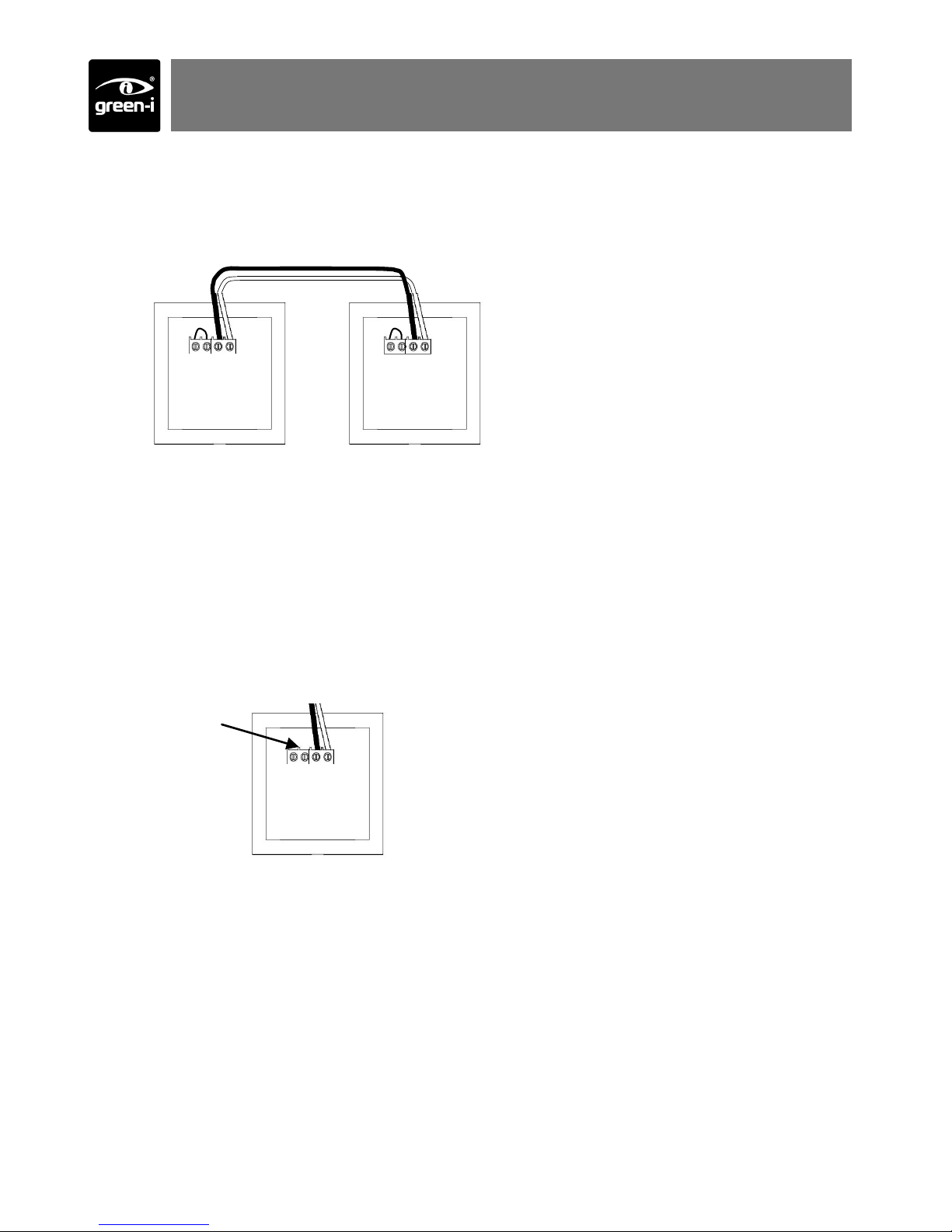
wiring—2 way switching
2 way switching
If more than one time lag switch is required to switch the lighting (e.g. At the top and bottom of a staircase) they can be wired in parallel, as in the diagram.
LINK com L1 LINK com L1
Locating ring
The GITL comes with an LED locating ring which is used to locate the buttons at night.
If the load does not turn off properly (e.g. lamp flickers, fan continues to run, contactor
does not open) then the LED needs to be disabled.
To achieve this, remove the link as shown below.
LINK com L1
Remove link to
disable LED
locating ring
Page 4

time setting
on
off
setting
green-i
locator
Short press—lights on for time period
Press for more than 5 seconds to activate
(see Activate section).
Short press—lights off
Press for more than 5 seconds to de-activate
(see Activate section).
battery
operation
Page 5

Remove front cover
Time setting
(determined by switch, see below)
5 sec—15min
15min—2hour
The lights will turn off after the time setting has finished. Clockwise = longer delay.
Standard operation
Bottom button de-activated. The lights
will turn off automatically, but will not
turn off manually.
15min-2hour time range
5sec-15min time range
setup
Page 6

Before using, the unit needs to be activated.
Press and hold the top button for more than 5 seconds.
The red LED will flash to indicate that has activated
and the unit will now operate.
If the unit is going to be out of use for prolonged peri-
ods (more than 6 months) it should be de-activated by
repeating the procedure above with the bottom button.
This will help to prolong battery life.
activate
Page 7

The internal battery should last more than 5 years
When it needs replacing, a red LED will flash on the front of the unit
Follow the steps opposite to replace the battery
Use only good quality, 9V alkaline batteries type PP3
1. Remove front
cover
2. Remove switch
cover
3. Lever out battery
4. Replace battery 5. Push into holder
6. Replace switch cover
7. Replace front cover
8. Activate
batteries
Page 8

Ref #WD264 Issue 3
C.P. Electronics Ltd
Brent Crescent
London
NW10 7XR
United Kingdom
Tel: + 44 (0) 333 900 0671
Fax: + 44 (0) 333 900 0674
www.green-iswitches.co.uk
enquiry@green-iswitches.co.uk
IMPORTANT NOTICE!
This device should be installed by a qualified electrician in
accordance with the latest edition of the IEE wiring regulations.
Due to our policy of continual product improvement CP Electronics reserves the right
to alter the specification of this product without prior notice.
FM 45789 EMS 534520
troubleshooting
Voltage 230VAC +/- 10%
Frequency 50Hz
Temperature 0ºC to 35ºC
Power 10A
Compliance BS EN60669-2-1 & BS EN55015
ratings
Lights flicker when off
Fan does not stop completely when off
Contactor does not open when off
Remove the link wire to disable the locating ring—see “wiring” section
EU registered design no. 000638069-0003, 000638069-0004
Recycling Information
According to the W EEE (2002/96) and Battery directive (2006/66), at end of the life of the product or
battery, you must dispose them at an appropriate collection point.
 Loading...