

Page 1
GREEN HOBBY Part No. Daisy G/E/Q
Building Instructions RC- Electric Aircraft "DAISY"
Motor or Glider Version
Technical Information:
Wingspan: 1480 mm
Length: 850 mm
Wing Airfoil Design: S 7055
Total Area: 24.1 dm 2
Flight Weight: 450 g Glider
800 g Electric
Electric Version: 1 AeroNaut Race 400 6.0V Motor Part No 7000/42
2 AeroNaut Race 480 7.2V Black Power Part No 7000/48
3 Mega Motor Brushless Mega 16.15.4 or Mega 400.12.
Nimh Battery: 8 cells choice of three - Part Nos KAN1050/GP1100/GP2000
Propeller: Folding 6x3" Glass + Integral Middlepiece Part No 7235/05
Or 6x3" Carbon + Integral Middlepiece Part No 7236/05
Or…. brushless option 7 x 4.5 blades + 3.2mm integral spinner
Assembly Notes for "DAISY"
Before opening the glue, oil the threads on all bolts with "After-Run" oil (available from Green Hobby),
this prevents all kind of problems later! Wherever instructions suggest gluing to the epoxy fuselage, preroughen up the smooth epoxy with fine sandpaper to give the glue a better "key" to adhere onto.
USEFUL TOOLS:
Needle or point nose pliers; "pin vise" modellers drill, drill bits from 2mm to 4mm, needle files, small wire
cutters, scalpel set, a little oil, epoxy glue, matchsticks for introducing epoxy into difficult to reach places,
soldering iron with electronic grade solder & flux paste, connecting plugs for nimh battery connections to
speed controller. All modelling tools are available from Green Hobby, and once purchased, will last you
for many years.
SAFETY: All electric aircraft have self start capability, this is absent in glow engined models. Because
of this both new modellers and modellers new to electric flight should always bear in mind the possibility
of the prop beginning to spin unexpectedly, if there is a nimh battery connected up. We call plugging in
the nimh "arming the plane", if your plane is armed, the transmitter should be "ON" to shout down
background interference that might switch the motor on. Ensure throttle stick is at down-throttle off.
The plane should be on a stand, so the prop is free to spin, and the motor will not burn out due to a
stalled prop. The modeller should also never stand to the side of a spinning prop - in front OK (if the
plane is stationery!), behind OK (recommended), but never to the side, a prop blade (or stone) could fly
out at high speed without warning, injuring anybody present there.
Remember: this is a REAL aircraft, it will be dangerous if not used carefully. Keep away from
bystanders. Even when being used properly, mishaps will occasionally happen, so due caution should
be exercised. Give respect to the propeller which is extremely sharp, the batteries which if shorted can
cause fire, the aircraft which needs maintenance before flights, your piloting skills which will improve but
never achieve perfection, and radio interference. In short - allow for problems and fly safely.
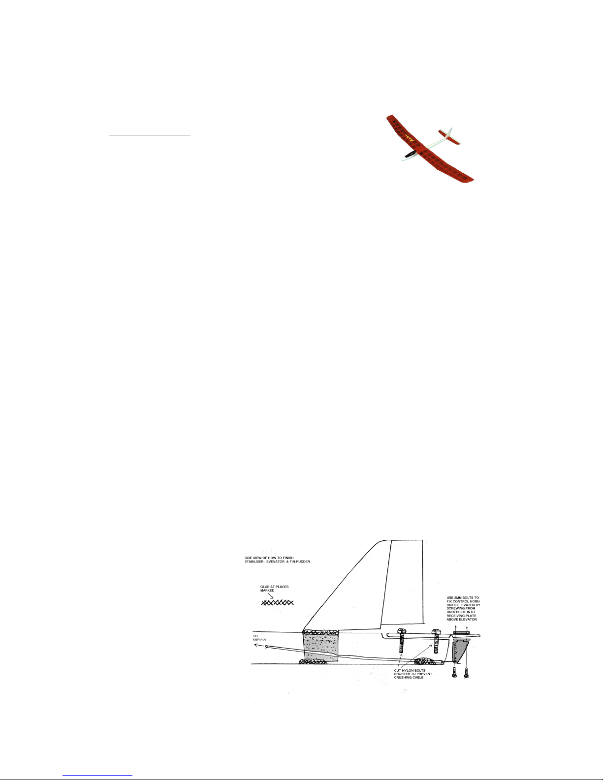
TAIL: Locate the two pairs of
holes in the top of the epoxy
fuselage, near the tail. The
rearward pair are tapped with a
thread to accept bolts holding the
stabiliser-elevator on later. The
forward pair of holes, not tapped
give you correct location of the
vertical stabiliser fin-rudder.
Using a Stanley knife or scalpel,
make two cuts joining the forward
pair of holes, and remove the thin
strip of epoxy, making a slot. Now
you can trial fit your fin, sanding
the slot with a fine file, or scraping
with the scalpel for best fit.
Page 2

Now fit the flat stabiliser -elevator onto the rearward tapped holes with two nylon bolts. You can now
see the clear space required under the vertical fin for flat stabiliser's free movement in flight. Trial fit fin
again until completely satisfied.
To fit the fin, apply epoxy to three
places - the fin sides above the
epoxy fuselage, the fin sides under
the epoxy fuselage, and the fin base
with epoxy gluing it to the fuselage
floor at the front edge of the fin.
A matchstick is handy for application
of glue to the difficult to reach places.
The best position is with the forward
edge of the fin base lower, touching
the fuselage floor. Lift the underside
of the fin's trailing edge up slightly by
resting the hinged rudder part on a
piece of matchstick until the glue
sets. This allows better access to
remove the elevator bolts after
completion, for easier transport of
your aircraft.
When happy, wipe off excess glue and leave to harden, with the fin in a perfectly vertical orientation.
Try to keep the amount of epoxy used to a minimum, it's heavy! Try also to avoid getting epoxy on the
flat stabiliser nylon bolts inside the fuselage, you pre-oiled them but even so don't take chances of
gluing them in permanently!
WINGS: Trial fit the wing pegs in wing holes. The front edges are best sanded slightly rounded for
easier fit into fuselage holes. If too tight the wing can not be put correctly onto the fuselage. So take a
little time here. Ease the fit (if necessary) by using a 4mm drill bit gently in a "pin vice drill" or between
your fingertips. Only when you can locate the pegs in the holes in the fuselage AND press the wing
trailing edge down so the nylon wing bolts can be screwed home without danger of breakage, THEN you
are ready to glue.
Oil the peg holes in the epoxy fuselage. The pegs have a tendency to slide too far into the wings while
dry fitting the wings, so try to have them go into the oiled fuselage holes without being pushed back into
the wing holes. Epoxy the pegs into the wings, wipe off excess epoxy, fit wings until glue sets.
After pegs harden into wing, remove the wings for convenience during the rest of the assembly.
MOTOR: This is pre-fitted in some versions of the kit. If not ask the Green Hobby team for an AeroNaut
6.0V Race 400 direct drive motor. The motor is fitted using two steel 2.5x8mm machine bolts. A
downward tilt, or downthrust is noticeable, this is intentional, and indeed is necessary for the excellent
flying characteristics of the aircraft on full power. If the prop is not pre-fitted, test the motor for free
rotation before fitting. Draw centreline on wood. Drill two 2.5mm holes 3mm out from the centre hole in
mounting plate.
It can happen that the motor mounting bolts reach sufficiently far into the motor that they foul the rotor
and prevent it spinning (stalled prop). If this happens, applying power will burn out your motor, so always
test the motor spins free before applying power. The cure is simple, add a couple of 3mm washers
under the bolt heads before the bolt goes through the hardwood motor mounting plate, this shortens the
length of bolt inside the motor, preventing any problem.
PROPELLER: Installation of the types of propeller supplied by Green Hobby is simple. It is pre-installed
on most non-aileron versions of the DAISY. Assemble the prop and fit onto the motor shaft with the
Allen keys supplied. Do not overtighten or you might "pull" the threads in the plastic prop assembly. Try
to have a 1 to 1.5mm gap between the propeller rear and the fuselage front, this aids cooling, prevents
the bolt heads fouling the prop, (same problem as for the motor bolts!), and also gives a tiny shock
absorber in bumpy landings as the prop can "give" a little as it slides back under the impact. Remember
to release the prop from possible locking up after any nose down landings however! The free-spinning
prop test for the motor finds any problems here, before power is applied.
ELECTRONIC SPEED CONTROLLER: This is pre-fitted on most non-aileron versions of DAISY. The
polarity of speed controller-to-motor connection is not vital to the life of the speed controller. This
determines the direction of prop rotation. The polarity of speed controller-to-nimh battery connection IS
VITAL if you get this wrong even for a split second you will short out the speed controller and destroy it.
No warranty will cover this damage. Read the manufacturers instructions carefully.
Solder on appropriate connecting plugs that prevent plugging in the wrong way round. Red-to-red positive (+), black-to-black-negative (-). Cover bare solder-wire ends with heatshrink of the correct
Page 3

colour (red/black), then the wires can not touch even while hanging-swinging round inside your model.
Greene Hobby has suitable plugs and heatshrink for this.
Don't try "testing" the motor holding the wires together in your hand - accidents happen.
NIMH Battery Electric Version: This is fitted using two postage stamp size patches of VELCRO on the
Nimh, and a 200mm strip of VELCRO on the fuselage base/lower sides. The idea is to be able to stick
the battery in the exact place that gets the aircraft balanced, see later.
You will get surprisingly long flights with the recommended nimh battery from your DAISY, it's height
retention is very good, even when turning.
At Green Hobby we have tried many batteries for balance and performance while testing prototypes.
We found that, of the many batteries available, three nimh packs give equally nice flying but give
different duration. One is slightly heavier, so they serve the dual function of steadying DAISY in variable
windy conditions. These 1050 mAh, 1100mAh and 2000 mAh DAISY nimhs are available from Green
Hobby. Both are easily fitted and removed from the fuselage for charging.
Glider Version Battery: In the Daisy Glider version, the weight of the missing motor must be
compensated for. So if you are fitting Daisy as a glider, the battery (4 cell receiver battery) goes in the
nose, and is held by blue tack putty. Add enough blue tack, so that the centre of gravity is identical to
motor version as explained later.
CONTROL CABLES & HORNS: Make a “Z” bend in one end of each steel inner cable (3mm between
90°bends). Cut each white outer 2 cm shorter than its steel inner. Slide inner into outer. Slide elevator
cable from tail up fuselage inside to servo area. Hook elevator control horn onto Z bend with flat
edge/holes to front, with holes adjacent with elevator hinge line. Trial fit, make pin pricks for horn
screws, drill elevator 2mm for screws, install control horn under elevator using screw receiver plate for
top of elevator. Horn may be glue-on type, if so, just drill an appropriate size hole and glue it into the
wood. Slide white outer so that it ends 1cm away from control horn (just inside fuselage end), and
carefully put a drop of epoxy on the outer 1/2 cm further inside, bonding outer to fuselage floor. Use a
wood strip for this and get no glue on the steel inner or controls will not work. Consider oiling the steel
inner for added safety, but take care because if oil gets on the outer, the glue will not bond outer
correctly to the fuselage.
Epoxy fuselage must be drilled for rudder cable. Locate the spot, 6mm to side of fin, and adjacent to the
rear end of the fin base on the fuselage outside. Drill 2mm for rudder cable. Open up the hole to an
oval shape by redrilling at the angle the cable will take. The pin vice is excellent for this job. Trial fit
rudder cable. If necessary use a rat tail needle file to free cable outer. The cable should point towards
the place where the control horn will be when installed.
This ensures that there is no sharp corner/bend in the cable that makes the steel inner tight in its
movements. A tight cable uses excessive servo power and shortens flight duration.
Slide control horn onto Z bend, flat edge forward, and trial fit control horn as before, with flat edge inline
with rudder hinge, in such a way that the cable points to the place of installation. Estimated location for
horn is near base of rudder with rear end of horn raised 2mm more than front so horn is inline with steel
inner. Drill rudder and install control horn. You now have a friction free cable to the rudder.
Slide the white outer along inner down to the control horn; put a smear of epoxy at the place that will go
through the epoxy fuselage. Slide outer back forwards, spinning gently until it ends 1-1 1/4cm from
control horn, and epoxy bonds where outer exits the fuselage. Once again, keep glue off the steel inner.
CANOPY: Take a piece of steel wire 220mm approx, lay it lengthwise on the inside of the canopy,
spread epoxy for 1cm each side of the middle of the wire leaving from each end to about 2cm inside
each end of the canopy glue free. Take the two 2cm wide ribbons of tissue and press the tissue ribbons
onto the wire & epoxy, spread epoxy into tissue. Tape in place with insulating or sticky tape, holding
wire and tissue to the concave canopy inside until hard. Later remove tape, wire is held as if glass
fibred into canopy. Trial fit canopy onto the fuselage. The wire now acts like a spring clip, bend the wire
so as to lie inside epoxy fuselage when canopy is fitted. Trim wire slightly for best fit. See picture.
SERVOS AND RC GEAR: Micro servos are assumed for this model, unless you intend to fly it as a
glider (no prop-motor-flight nimhs). Even as a glider micro servos are the way to do it. Ask the Green
Hobby team for suggestions on best micro servos.
Locate & cut 2 or 3 servo bearers, from balsa strip as shown. Illustration shows a plywood capping
which is not necessary, so use balsa as supplied. Lengths of 38mm 40mm and 42mm (40-50mm for
Glider version) are about right but slightly oversize. The idea is to trial fit, sand it a little and trial fit
again. If they are wedged in with force, an ugly bulge will appear on the epoxy fuselage outside surface!
Tweezers and point nose pliers help here. Due to the round fuselage shape the lower part of the
bearers will be sanded shorter length than the ply hardened top surface.
Epoxy wood in place with servo resting on the bearer to ensure correct spacing.
Illustration shows servos side by side, this is tight to arrange, but preferable. Inline servos are an option
using the third servo bearer. There is more finger space this way! For durability spread a thin layer of
epoxy 1cm around the glued area on the fuselage inner wall as shown.
Page 4
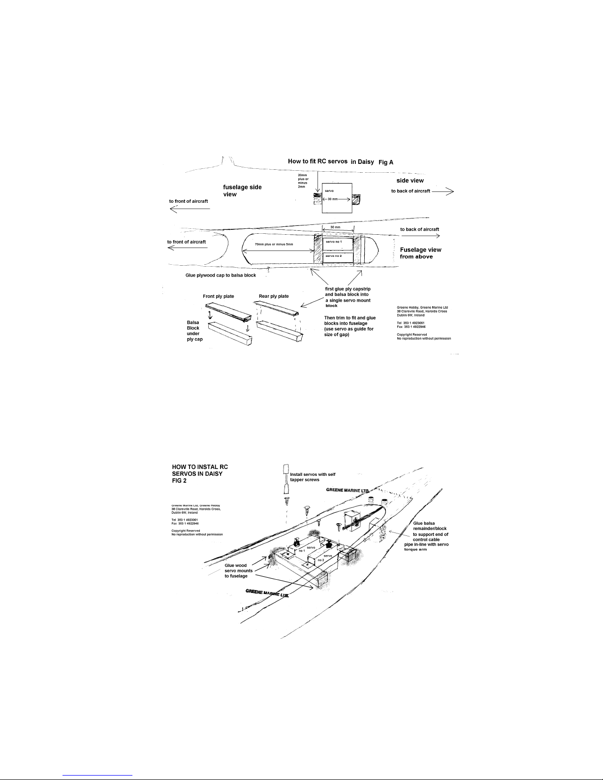
The nicest way by far of connecting up the steel inner to the servo arms is using AeroNaut "Anschluss"
adjustable servo connectors Part No 7490/07, we recommend these highly. They project about 6mm up
from the servo top, so make sure your bearers & servos are fitted low enough or the wing might, when
put on later, foul (touch) and stop the servo from turning! Fit the "anschluss" connectors to the servo
arms, and tighten the grub screw onto the steel inner.
(If the inner is very fine and sits under the grubscrew without being locked, use the following trick: Slide
a 1cm section of white outer over the inner where it goes through the connector on the servo arm. The
grub screw locks onto the outer and inner at the same time, but the inner can still just barely move.
Make final adjustments, then make a sharp bend in the unused extreme forward end of both 1 cm outer
piece and inner, locking them together)
If you don't want the easy adjustments the "Anschluss" connectors provide, you should make Z-bends in
the steel inner so the servo arm will be able to push and pull equal distances of steel inner when
operating in flight. Take care to get this right first time, but don't worry if you destroy the inner, the
Greene Hobby team always carry stocks of spare steel inner wire (0.8mm steelwire).
Now you need to bond down the ends of the white outer 1-2cm rearwards of the servo arm-steel inner
connections. NOTE it is a good idea to fit the (oiled) wing bolts, without the wing, before bonding the
cable outers at this end. This is because it is possible to put the cables in such a place that when fitting
the wing later, the wing bolt wants to go through the cables!
The illustration shows a spare piece of balsa or ply supporting the end of the cable outer. We prefer to
bond to the fuselage roof beside the wing bolts but not touching them. We do this with the fuselage held
upside down and work from below. You can reach in with a wood strip with a drop of epoxy on the end
and bond outer to wood, and wood to fuselage sides. You will find a matchstick bent into a banana
shape is the perfect tool to apply the epoxy. Once again, avoid getting epoxy where it should not go. Do
not hurry. Take your time and this works out into a very neat job.
Page 5

When servos are finished, install the receiver where shown, protected by a little bubble wrap, or rubber.
PRE FLIGHT: Do a trial and error process of moving the nimh forwards and backwards until, with wings
fitted, the centre of gravity is in the place shown. If in doubt - ask our staff. The bottom line is that when
supported by a fingertip under each wing spar, the aircraft should hang nose down slightly. Otherwise it
will be hard or even impossible to fly. When the correct battery position is found, make marks inside the
fuselage so it can be popped straight into the intended place time after time. Try 5mm behind motor
backplate as starting place for battery location positioning. This location gives docile handling.
Switch on the radio, then plug in the nimh, arming the plane. Ensure that nothing is inline with prop and
prop is free to rotate. This is because you don't yet know if your radio is set up with full throttle or zero
throttle when stick is "down". If necessary switch the radio until throttle range is correctly oriented with
zero at the low end.
Now move all sticks to mid point on the radio (throttle stick at zero-lowest position). If the rudder &
elevator are now at mid point – OK - if not, adjust the servo "anschluss" connectors, sliding the steel
inner until flap is centred. Lock up grubscrew.
Run motor in with 2-3 nimh cycles at 1/4 throttle. This improves motor power later, and cycling the nimh
brings it from its dormant "store-safely" state up to manufacturer specification.
FIRST FLIGHT: For the first flight a calm day is essential even if you are an experienced flier. All
aircraft are different so you need the best conditions to get used to new aircraft. All wind is bad for a first
flight. This applies doubly to beginners. Bring the receiver aerial cable back and thread through a
pinhole in the vertical fin. Range test the RC gear with antenna down at 100 metres, with throttle both
on and off. If "glitching" occurs, try routing power cables away from the receiver.
Hand launch with a horizontal throw (like throwing a dart) on about 3/4 throttle towards whatever wind is
present. Full throttle is not necessary, as DAISY is an exceptionally light model for its size.
BEGINNERS NOTES: Build up extra airspeed on the level before trying to climb as hard climb will slow
the aircraft down somewhat. Climbing too soon after takeoff often catches beginners out.
Turning too sharp is the next beginners mistake to avoid, so make turns incremental at first. Try a one
second jab left to initiate the turn, then a 1/4 size jab right to level her out, observe the effect and then
do it again if necessary.
Remember to throttle back to flying-cruising speed when at a safe height. Then switch engine off and
fold the prop, but keep the slight downhill attitude while gliding so as to maintain flying speed.
Due to the wing plan and airfoil design no more comments are necessary. DAISY is a lovely flier. The
non-aileron version is capable of very tight turns without wingtip stall compared to many other similar but
less well designed aircraft, so you will be pleasantly surprised by its agility. The aileron version, while
not so suitable for learners, is a most pleasing model to fly with it's more precise manoeuvers, and is
also good for slope soaring.
We wish you many enjoyable flights with your DAISY.
Green Hobby Flight Team
Green Hobby, Greene Marine House., 38 Clareville Road, Harolds Cross, Dublin 6W, Ireland
Tel: 4928776 Fax 4922946
Page 6
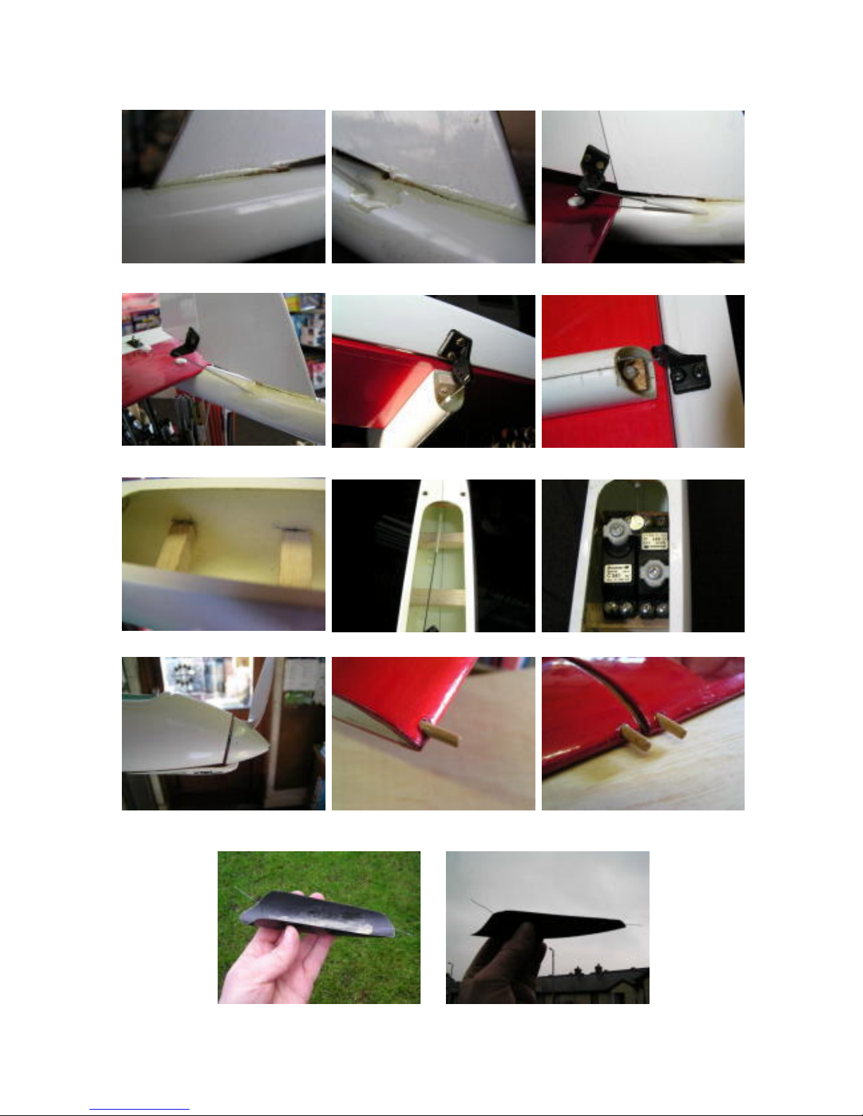
Glue in fin Note location of cable drilling Cable & fin finished
Another view … Elevator cable installed Elevator linkage from below
Servo bearers glued in Bearer location from above Servo & cable connectors
Propeller downthrust Wing pin ready to glue Wings finished
Canopy with epoxied-in wire Bend the wire like this, to clip on canopy
 Loading...