

Green Hobby Daisy G, Daisy E, Daisy Q Building Instructions
GREEN HOBBY Part No. Daisy G/E/Q
Building Instructions RC- Electric Aircraft "DAISY"
Motor or Glider Version
Technical Information:
Wingspan: 1480 mm
Length: 850 mm
Wing Airfoil Design: S 7055
Total Area: 24.1 dm 2
Flight Weight: 450 g Glider
800 g Electric
Electric Version: 1 AeroNaut Race 400 6.0V Motor Part No 7000/42
2 AeroNaut Race 480 7.2V Black Power Part No 7000/48
3 Mega Motor Brushless Mega 16.15.4 or Mega 400.12.
Nimh Battery: 8 cells choice of three - Part Nos KAN1050/GP1100/GP2000
Propeller: Folding 6x3" Glass + Integral Middlepiece Part No 7235/05
Or 6x3" Carbon + Integral Middlepiece Part No 7236/05
Or…. brushless option 7 x 4.5 blades + 3.2mm integral spinner
Assembly Notes for "DAISY"
Before opening the glue, oil the threads on all bolts with "After-Run" oil (available from Green Hobby),
this prevents all kind of problems later! Wherever instructions suggest gluing to the epoxy fuselage, preroughen up the smooth epoxy with fine sandpaper to give the glue a better "key" to adhere onto.
USEFUL TOOLS:
Needle or point nose pliers; "pin vise" modellers drill, drill bits from 2mm to 4mm, needle files, small wire
cutters, scalpel set, a little oil, epoxy glue, matchsticks for introducing epoxy into difficult to reach places,
soldering iron with electronic grade solder & flux paste, connecting plugs for nimh battery connections to
speed controller. All modelling tools are available from Green Hobby, and once purchased, will last you
for many years.
SAFETY: All electric aircraft have self start capability, this is absent in glow engined models. Because
of this both new modellers and modellers new to electric flight should always bear in mind the possibility
of the prop beginning to spin unexpectedly, if there is a nimh battery connected up. We call plugging in
the nimh "arming the plane", if your plane is armed, the transmitter should be "ON" to shout down
background interference that might switch the motor on. Ensure throttle stick is at down-throttle off.
The plane should be on a stand, so the prop is free to spin, and the motor will not burn out due to a
stalled prop. The modeller should also never stand to the side of a spinning prop - in front OK (if the
plane is stationery!), behind OK (recommended), but never to the side, a prop blade (or stone) could fly
out at high speed without warning, injuring anybody present there.
Remember: this is a REAL aircraft, it will be dangerous if not used carefully. Keep away from
bystanders. Even when being used properly, mishaps will occasionally happen, so due caution should
be exercised. Give respect to the propeller which is extremely sharp, the batteries which if shorted can
cause fire, the aircraft which needs maintenance before flights, your piloting skills which will improve but
never achieve perfection, and radio interference. In short - allow for problems and fly safely.
TAIL: Locate the two pairs of
holes in the top of the epoxy
fuselage, near the tail. The
rearward pair are tapped with a
thread to accept bolts holding the
stabiliser-elevator on later. The
forward pair of holes, not tapped
give you correct location of the
vertical stabiliser fin-rudder.
Using a Stanley knife or scalpel,
make two cuts joining the forward
pair of holes, and remove the thin
strip of epoxy, making a slot. Now
you can trial fit your fin, sanding
the slot with a fine file, or scraping
with the scalpel for best fit.

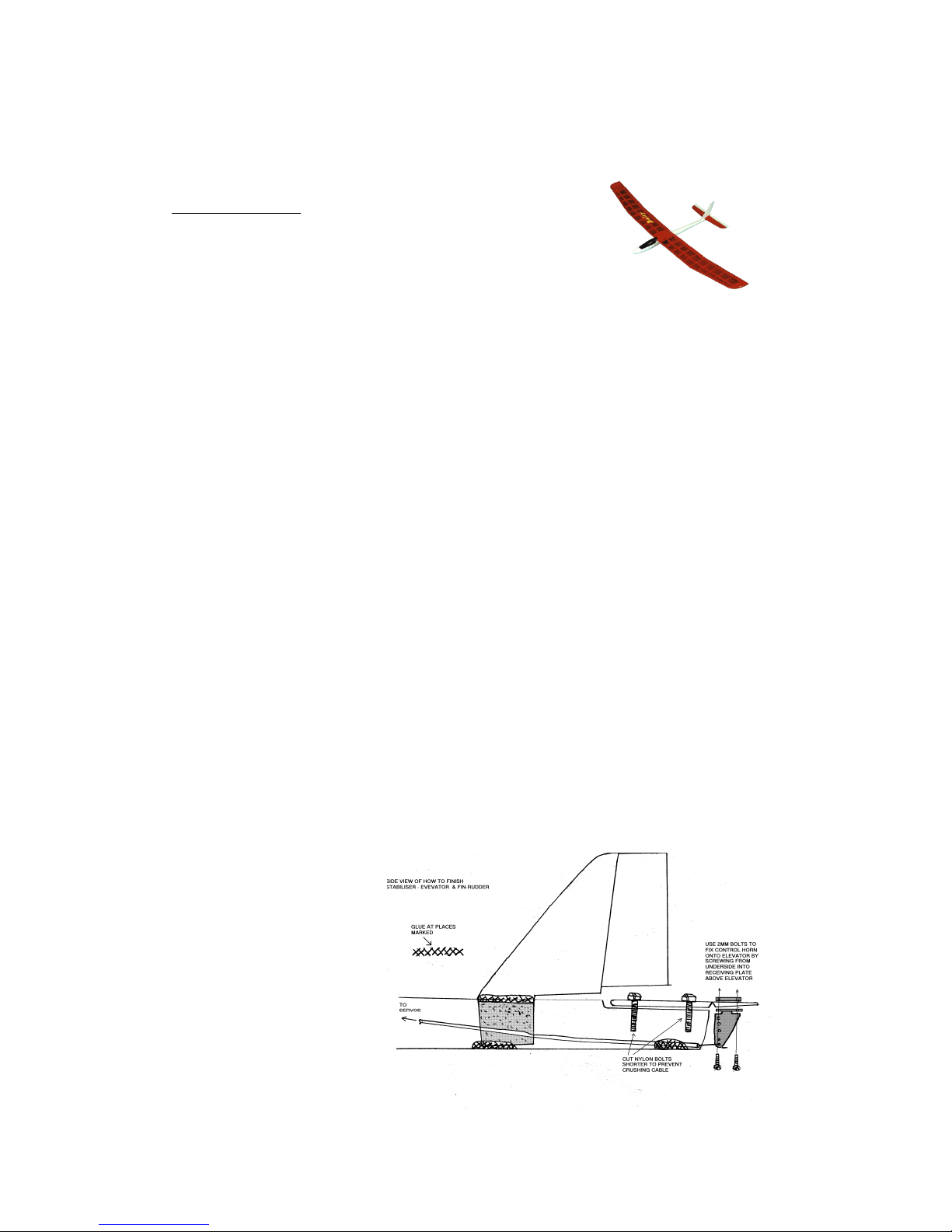
Now fit the flat stabiliser -elevator onto the rearward tapped holes with two nylon bolts. You can now
see the clear space required under the vertical fin for flat stabiliser's free movement in flight. Trial fit fin
again until completely satisfied.
To fit the fin, apply epoxy to three
places - the fin sides above the
epoxy fuselage, the fin sides under
the epoxy fuselage, and the fin base
with epoxy gluing it to the fuselage
floor at the front edge of the fin.
A matchstick is handy for application
of glue to the difficult to reach places.
The best position is with the forward
edge of the fin base lower, touching
the fuselage floor. Lift the underside
of the fin's trailing edge up slightly by
resting the hinged rudder part on a
piece of matchstick until the glue
sets. This allows better access to
remove the elevator bolts after
completion, for easier transport of
your aircraft.
When happy, wipe off excess glue and leave to harden, with the fin in a perfectly vertical orientation.
Try to keep the amount of epoxy used to a minimum, it's heavy! Try also to avoid getting epoxy on the
flat stabiliser nylon bolts inside the fuselage, you pre-oiled them but even so don't take chances of
gluing them in permanently!
WINGS: Trial fit the wing pegs in wing holes. The front edges are best sanded slightly rounded for
easier fit into fuselage holes. If too tight the wing can not be put correctly onto the fuselage. So take a
little time here. Ease the fit (if necessary) by using a 4mm drill bit gently in a "pin vice drill" or between
your fingertips. Only when you can locate the pegs in the holes in the fuselage AND press the wing
trailing edge down so the nylon wing bolts can be screwed home without danger of breakage, THEN you
are ready to glue.
Oil the peg holes in the epoxy fuselage. The pegs have a tendency to slide too far into the wings while
dry fitting the wings, so try to have them go into the oiled fuselage holes without being pushed back into
the wing holes. Epoxy the pegs into the wings, wipe off excess epoxy, fit wings until glue sets.
After pegs harden into wing, remove the wings for convenience during the rest of the assembly.
MOTOR: This is pre-fitted in some versions of the kit. If not ask the Green Hobby team for an AeroNaut
6.0V Race 400 direct drive motor. The motor is fitted using two steel 2.5x8mm machine bolts. A
downward tilt, or downthrust is noticeable, this is intentional, and indeed is necessary for the excellent
flying characteristics of the aircraft on full power. If the prop is not pre-fitted, test the motor for free
rotation before fitting. Draw centreline on wood. Drill two 2.5mm holes 3mm out from the centre hole in
mounting plate.
It can happen that the motor mounting bolts reach sufficiently far into the motor that they foul the rotor
and prevent it spinning (stalled prop). If this happens, applying power will burn out your motor, so always
test the motor spins free before applying power. The cure is simple, add a couple of 3mm washers
under the bolt heads before the bolt goes through the hardwood motor mounting plate, this shortens the
length of bolt inside the motor, preventing any problem.
PROPELLER: Installation of the types of propeller supplied by Green Hobby is simple. It is pre-installed
on most non-aileron versions of the DAISY. Assemble the prop and fit onto the motor shaft with the
Allen keys supplied. Do not overtighten or you might "pull" the threads in the plastic prop assembly. Try
to have a 1 to 1.5mm gap between the propeller rear and the fuselage front, this aids cooling, prevents
the bolt heads fouling the prop, (same problem as for the motor bolts!), and also gives a tiny shock
absorber in bumpy landings as the prop can "give" a little as it slides back under the impact. Remember
to release the prop from possible locking up after any nose down landings however! The free-spinning
prop test for the motor finds any problems here, before power is applied.
ELECTRONIC SPEED CONTROLLER: This is pre-fitted on most non-aileron versions of DAISY. The
polarity of speed controller-to-motor connection is not vital to the life of the speed controller. This
determines the direction of prop rotation. The polarity of speed controller-to-nimh battery connection IS
VITAL if you get this wrong even for a split second you will short out the speed controller and destroy it.
No warranty will cover this damage. Read the manufacturers instructions carefully.
Solder on appropriate connecting plugs that prevent plugging in the wrong way round. Red-to-red positive (+), black-to-black-negative (-). Cover bare solder-wire ends with heatshrink of the correct
 Loading...