

Page 1

1
RT-21 Az-El Controller
Manual addendum to RT-21 - September 25, 2018
Overview:
The RT-21 Az-El controller consists of two RT-21 units with a shared power
supply and shared chassis. The unit features a pair of new OLED displays for
sharp, crisp viewing, two main RT-21 PCB each with their own RS232 port, USB
port, and 8 position terminal strip on the rear panel. When teamed with the free
GH Tracker software from the website, this unit provides a fully automatic,
hands-free controller for many different combinations of Az-El rotator schemes.
http://www.greenheronengineering.com/RT_Software.php
The lower board is configured for azimuth and uses the lower display, serial
connectors, and terminal strip. The upper board is configured for elevation and
uses the upper display, serial connectors, and terminal strip.
Compatibility:
The RT-21 Az-El is suitable for:
Yaesu G5400 Az-El units
Yaesu G5500 Az-El units
Alfa Spid Az-El units
M2 Az (OR28900) with MT1000, MT3000 units
Create Design Az and El rotators – (RC5, ERC)
Any combination of Azimuth and Elevation rotators that:
a. Both use AC or Both use DC motors – AND -
b. Both use rotators that are within the capabilities of a standard RT-21
(The RT-21 Az-El is compatible with the Prosistel Az El system as well. Please
contact us for information regarding this rotator.)
Examples of systems that cannot use an RT-21 Az-El. These types of systems
would require separate azimuth and elevation RT-21 controllers:
1. Azimuth using a Prop Pitch motor (with PWM speed control) cannot be
accommodated with the RT-21 Az-El because the Prop Pitch requires the
10 amp motor supply. The RT-21pp must be used for the Prop Pitch
azimuth rotator. (EXCEPTION – we can configure the azimuth side for
relay control without PWM speed control capability, and then utilize an RT21 Az-El as long as we match the relay voltage type (ac or dc) with your
choice of elevation rotators.)
2. Azimuth with A Yaesu G2800, and elevation of G550 cannot be
accommodated because the G2800 uses DC motor, while the G550 uses
an AC Motor.
The RT-21 Az-El is compatible with SETUP Utility version 2.1 and later.
Page 2

2
Features:
RT-21 SETUP UTILITY pc software supports all the RT-21 Az-El is supported in
version 2.1 that is available on the website at:
http://www.greenheronengineering.com/RT_Software.php
The following standard RT-21 features are not included in the RT-21 Az-El
Controller:
1. Master/Slave and Counter-rotation features.
2. Alternate Offset features
3. Internal AC motor capacitor that would be required for some AC motor
units, Green Heron will supply a suitable capacitor for externally mounting
at your rotator, or on the rear of the RT-21 Az-El.
The following are new or changed features with the RT-21 Az-El.
1. Additional separate Point & Shoot knob for Elevation Control.
2. The two individual main boards can each accept the same, or different
voltage tap from the main transformer.
3. New rear terminal PCB inside RT-21 Az-El uses plug-in sockets for the
protective Transorbs. This allows lightning protector replacement without
requiring any soldering.
4. Supports any elevation range up to 180 degrees. Soft Limits may be set
to limit to any range desired.
5. Default settings allow 90 degree elevation, and South Center azimuth.
6. Manual (front panel button) control is selectable from Az to El by pressing
the CANCEL button for ~ ½ second. Display showing “MAN” indicates
which is active. (Computer control and Point & Shoot control are always
active for both Az and El.)
7. Elevation control below the horizon for parking, or maintenance can be
supported in the controller.
8. Elevation Mode will not change with a System RESET. It is possible to
change Elevation Mode with SETUP Utility, but there should be no reason
to do this unless a CPU chip, or main PCB is being replaced. The correct
setting for Elevation Mode is made at the factory.
The following section includes connection and setup information for some of
the most common Az/El and Elevation only rotators that are supported. Use
the RT-21 manual for separate Az and El combinations that are not described
here.
Page 3
3
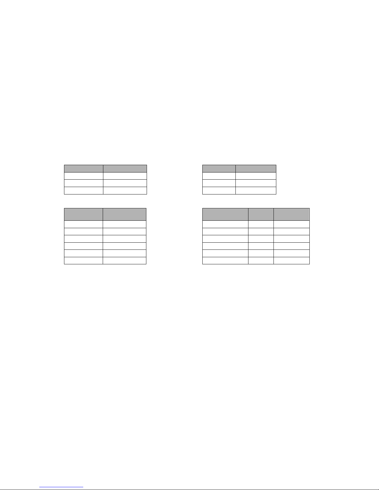
YAESU G-5400/G5500 Az El
(Also G550 Elevation)
CONNECTIONS AND SETUPS
Azimuth - Use SETUP->OPTION = G5400 or G5500
Elevation – Use SETUP ->OPTION = Yaesu
AC Motor Transformer Taps
Jumper Position Transformer J9 Connection
J10 1-2 Brown J9-1
J14 Open Orange J9-2
J12 1-2
Position Feedback Rotor Connections
Jumper Position Function Yaesu # RT-21
REF 1 5
J5 1-2 POS 2 4
J6 1-2 GND 3 3
J16 1-2 MOT CCW 4 2
MOT CW 5 1
MOT COM 6 3
NOTE: Term 3 gets 2 wires
NOTES:
1. There should be no calibration required because the default settings provide
normal accuracy for these rotators. If you wish to refine the calibration for more
accuracy, you will need to calibrate the endpoints (180 to 180 for azimuth, and 0
to 90 for Elevation) using either RT-21 SETUP Utility, or the front panel
calibration procedure. This procedure can be found in the RT-21 manual for
various rotator types, contact the factory if you need assistance.
2. Default elevation is 90 degrees. These rotators allow for 180 degrees of
“elevation” control. To change the RT-21 to allow different elevation angles, set
the “CW” Limit to the value you want to allow. To allow full 180 degrees, set the
CW Limit to 180. To allow only 70 degrees of elevation, set the CW Limit to 70.
3. If you are using the G550, setup the elevation according to this page. For your
specific Azimuth rotator (must be an AC motor type) you would use the appendix
page for your desired azimuth rotator.
4. If your azimuth rotator is a G5400, HAMx or T2X rotator, you will need to add a
motor start capacitor across terminals 1 and 2 of the RT-21 azimuth barrier strip.
Green Heron will provide you with an appropriate capacitor on request.
Page 4
4
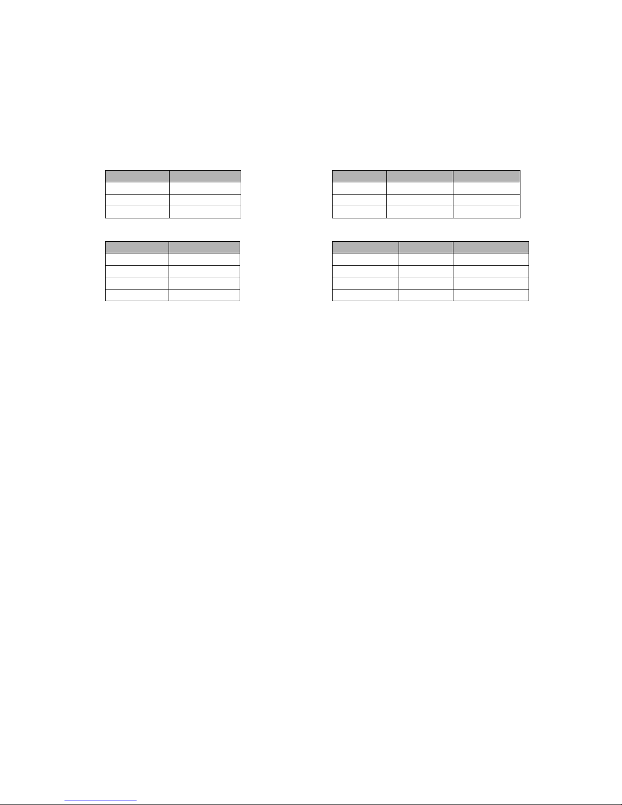
M2 ORION 2800 DC/MT-1000 AZ EL
Azimuth - Use SETUP->OPTION = Orion
Elevation – Use SETUP ->OPTION = MT1000
DC Motor Transformer Taps
Jumper Position Transformer J9 Connection NOTE
J10 2-3 Brown J9-3
J14 2-3 Orange J9-4
J12 2-3
Position Feedback Rotor Connections
Jumper Position Function M2 RT-21
J5 2-3 MOT CW/UP 1 (Black) 1
J6 2-3 MOT CCW/DN 2 (White) 2
J16 1-2 POS 5 (Orange) 4
GND 6 (Blue) 3
(Opt: cable shield to 6-32 ground stud (if shield used)
(Shielded rotor cable is not required with an RT-21)
CALIBRATION PROCEDURE
Existing System from front panel (antenna already installed and working
1. Look at the current direction of the antenna and note the true heading/elevation. Then press
SETUP until the displays says “Setup”, then let go and you will be in the “Calibrate” item.
Turn the knob until NEW VALUE is equal to the current true heading or elevation. Press
CHANGE, then press SAVE. Do this for both azimuth and elevation.
New system
1. (Always test and calibrate on the bench before installing if at all possible). M2 and Green
Heron always ship these rotators and controllers preset to the center of their rotation range.
In most cases, simply connect as in the Rotor Connections above, and verify that it works. No
other calibration is required. Then turn to a convenient heading, and once the rotator is
installed, bolt the mast in with the antennas matching the displayed heading. Center is best
as that makes it easier to get the rotor loop correct.
If you need to re-find the center for any reason: (in order of ease)
1. Using SETUP Utility (recommended)
a. Click on Auto-Cal Orion. Unit will run CCW until it is sure it found the CCW limit switch,
then will turn rotator to its center of rotation and calibrate it there.
2. Use Front panel SETUP
a. Press SETUP and hold, display will say “Setup” then ~ 6 seconds later, will change to
say “Auto Cal, Orion”. Follow the displayed prompt. This will leave the rotator at its
extreme CCW limit, and calibrate it there.
3. Manually find the center (hardest)
a. Find the CCW limit switch by turning the rotor with the CCW button as far as it will go
CCW. If you reach the soft limit shown by the “<” on the LCD, then go into SETUP>CALIBRATE and change the heading to full CW position of the knob, press CHANGE,
then SAVE. Now continue to turn the rotator CCW until you get the “ERROR, NO
MOTION”. This is the CCW mechanical limit.
b. Using the CW button, turn the antenna 14 degrees CW from this point until the display
reads the recorded heading above + 14 degrees. This moves the rotator out of the 14
degree Over-travel zone.
c. Go back into SETUP->CALIBRATE. Turn the knob fully CCW (New Value = 0 if you
have the normal South Center), then press CHANGE, and then SAVE.
Page 5
5
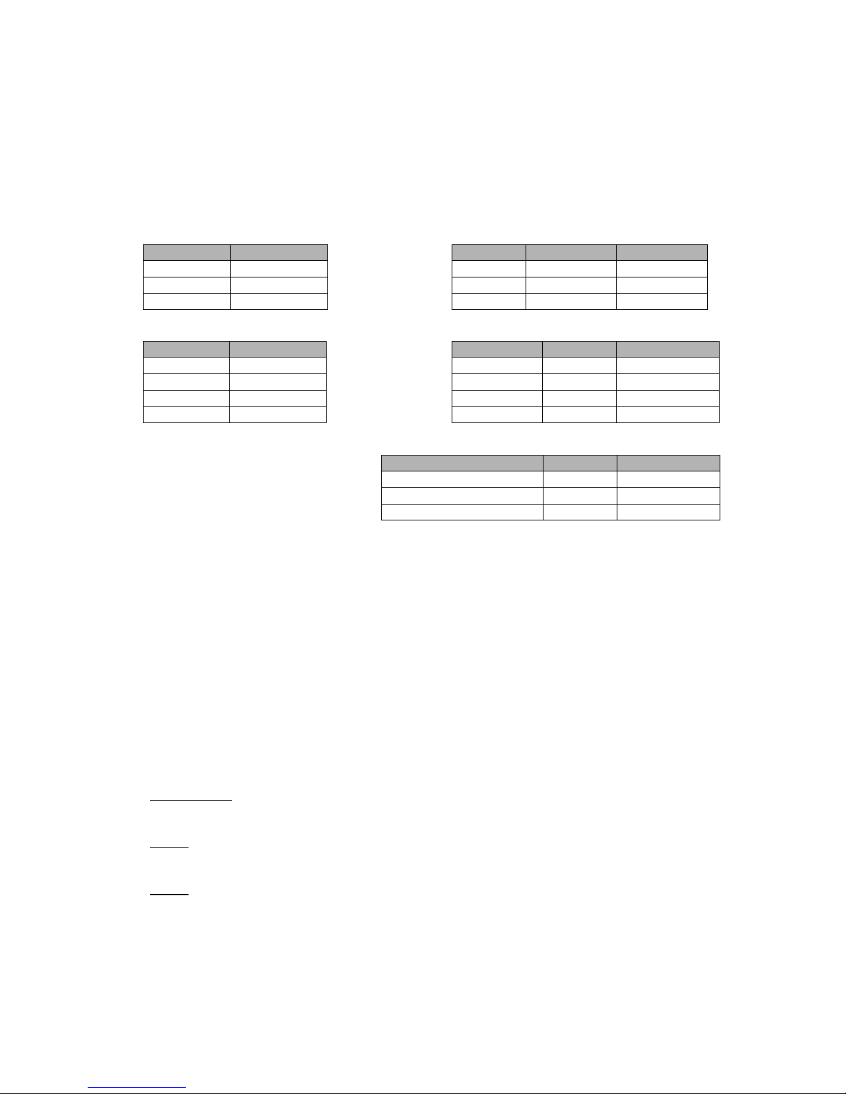
Alfaspid RAS, BIG RAS, REAL
Azimuth - Use SETUP->OPTION = SPID
Elevation – Use SETUP ->OPTION = SPID
DC Motor Transformer Taps
Jumper Position Transformer J9 Connection NOTE
J10 2-3 Brown J9-3
J14 2-3 Yellow J9-4
J12 2-3
Position Feedback Rotor Connections Standard
Jumper
Position
Function
SPID RT-21
J5 2-3 MOT CW 1 2
J6 2-3 MOT CCW 2 1
J16 1-2 GND 3 3
POS(Position) 4 4
Sensor Connections Hi Res only
These sensor connections for Hi Res are used instead of the terms 3
and 4 connections that are utilized with the Standard SPID
CALIBRATION PROCEDURE
1. Verify that your rotor is 1 pulse/degree (Pulse Divider = 360) which is the standard
number for the RAS and REAL. The Big RAS typically is ½ degree resolution for a
Pulse divisor requirement of 720. Some units have other divisors, and the High
Resolution versions should be 2880. The RT-21 supports all versions, contact us if
you need assistance determining your correct Divider value.
2. The azimuth rotors have no limit switches, so be certain you do not over-travel beyond
the limits of your rotor loops!!!! Adjust the antenna position on the mast or turn with the
CW or CCW buttons until the antenna is at some physical known heading or elevation.
The elevation rotators do contain limit switches to contain rotation to 180 degrees.
3. Go to SETUP/CALIBRATE and match the displayed heading with the visual, actual
heading or elevation into the “NEW VALUE = “ by turning the front panel knob.
IMPORTANT: Insure that your coax loop around the rotator will support your rotating
range. The Alfa Spid has no internal limit switches on the azimuth rotator.
NOTE: If you rotator turns backwards, simply swap the motor wires between terminals
1 & 2.
NOTE: If your indicator shows ½ of the actual travel (you turn it 10 degrees on the
indicator and the antenna actually turns 20), then change the Pulse Divider to
720.
Function SPID RT-21
IN IMP 1 (or IN IMP2) 3 (or 2) 4
12 VDC (for Sensor Power) 6 and 7 5
GND (for Sensor) 8 and 9 3
Page 6

6
Create ERC5x
Use the RT-21 Manual Appendix A.5 for Connections and Setups for both RC5 and
ERC5 rotators.
Elevation ERC5 CALIBRATION PROCEDURE
1. Turn the rotor to horizon 0 degrees elevation with the CCW (Down) button watching the
antenna, not the display
2.
Press the CANCEL and CCW (DOWN) together and hold 2 seconds until the display reads “CAL
CCW = xxx” where xxx should be a number < 50. (It may be helpful to press the CANCEL
“slightly” ahead of the CCW button.)
3.
Turn the rotor using the CW (Up) button until the antenna is physically pointed straight up,
watching the antenna, not the display.
4.
Press the CANCEL and CW (Up) together and hold 2 seconds until the display reads “CAL CW =
xxx” where xxx should be a number > 800. (It may be helpful to press the CANCEL “slightly”
ahead of the CCW button.)
NOTE: You may also use the SETUP Utility instead of the front panel. It’s much
easier to see and set the calibration points with the computer method.
NOTE: The ERC allows about 100 degrees of rotation. You may allow rotation
beyond 90 degrees only if you change the CW limit above the default of 90.
Page 7

1
RT-21 Az-El Controller
Manual addendum to RT-21 - September 25, 2018
Overview:
The RT-21 Az-El controller consists of two RT-21 units with a shared power
supply and shared chassis. The unit features a pair of new OLED displays for
sharp, crisp viewing, two main RT-21 PCB each with their own RS232 port, USB
port, and 8 position terminal strip on the rear panel. When teamed with the free
GH Tracker software from the website, this unit provides a fully automatic,
hands-free controller for many different combinations of Az-El rotator schemes.
http://www.greenheronengineering.com/RT_Software.php
The lower board is configured for azimuth and uses the lower display, serial
connectors, and terminal strip. The upper board is configured for elevation and
uses the upper display, serial connectors, and terminal strip.
Compatibility:
The RT-21 Az-El is suitable for:
Yaesu G5400 Az-El units
Yaesu G5500 Az-El units
Alfa Spid Az-El units
M2 Az (OR28900) with MT1000, MT3000 units
Create Design Az and El rotators – (RC5, ERC)
Any combination of Azimuth and Elevation rotators that:
a. Both use AC or Both use DC motors – AND -
b. Both use rotators that are within the capabilities of a standard RT-21
(The RT-21 Az-El is compatible with the Prosistel Az El system as well. Please
contact us for information regarding this rotator.)
Examples of systems that cannot use an RT-21 Az-El. These types of systems
would require separate azimuth and elevation RT-21 controllers:
1. Azimuth using a Prop Pitch motor (with PWM speed control) cannot be
accommodated with the RT-21 Az-El because the Prop Pitch requires the
10 amp motor supply. The RT-21pp must be used for the Prop Pitch
azimuth rotator. (EXCEPTION – we can configure the azimuth side for
relay control without PWM speed control capability, and then utilize an RT21 Az-El as long as we match the relay voltage type (ac or dc) with your
choice of elevation rotators.)
2. Azimuth with A Yaesu G2800, and elevation of G550 cannot be
accommodated because the G2800 uses DC motor, while the G550 uses
an AC Motor.
The RT-21 Az-El is compatible with SETUP Utility version 2.1 and later.
Page 8

2
Features:
RT-21 SETUP UTILITY pc software supports all the RT-21 Az-El is supported in
version 2.1 that is available on the website at:
http://www.greenheronengineering.com/RT_Software.php
The following standard RT-21 features are not included in the RT-21 Az-El
Controller:
1. Master/Slave and Counter-rotation features.
2. Alternate Offset features
3. Internal AC motor capacitor that would be required for some AC motor
units, Green Heron will supply a suitable capacitor for externally mounting
at your rotator, or on the rear of the RT-21 Az-El.
The following are new or changed features with the RT-21 Az-El.
1. Additional separate Point & Shoot knob for Elevation Control.
2. The two individual main boards can each accept the same, or different
voltage tap from the main transformer.
3. New rear terminal PCB inside RT-21 Az-El uses plug-in sockets for the
protective Transorbs. This allows lightning protector replacement without
requiring any soldering.
4. Supports any elevation range up to 180 degrees. Soft Limits may be set
to limit to any range desired.
5. Default settings allow 90 degree elevation, and South Center azimuth.
6. Manual (front panel button) control is selectable from Az to El by pressing
the CANCEL button for ~ ½ second. Display showing “MAN” indicates
which is active. (Computer control and Point & Shoot control are always
active for both Az and El.)
7. Elevation control below the horizon for parking, or maintenance can be
supported in the controller.
8. Elevation Mode will not change with a System RESET. It is possible to
change Elevation Mode with SETUP Utility, but there should be no reason
to do this unless a CPU chip, or main PCB is being replaced. The correct
setting for Elevation Mode is made at the factory.
The following section includes connection and setup information for some of
the most common Az/El and Elevation only rotators that are supported. Use
the RT-21 manual for separate Az and El combinations that are not described
here.
Page 9

3
YAESU G-5400/G5500 Az El
(Also G550 Elevation)
CONNECTIONS AND SETUPS
Azimuth - Use SETUP->OPTION = G5400 or G5500
Elevation – Use SETUP ->OPTION = Yaesu
AC Motor Transformer Taps
Jumper Position Transformer J9 Connection
J10 1-2 Brown J9-1
J14 Open Orange J9-2
J12 1-2
Position Feedback Rotor Connections
Jumper Position Function Yaesu # RT-21
REF 1 5
J5 1-2 POS 2 4
J6 1-2 GND 3 3
J16 1-2 MOT CCW 4 2
MOT CW 5 1
MOT COM 6 3
NOTE: Term 3 gets 2 wires
NOTES:
1. There should be no calibration required because the default settings provide
normal accuracy for these rotators. If you wish to refine the calibration for more
accuracy, you will need to calibrate the endpoints (180 to 180 for azimuth, and 0
to 90 for Elevation) using either RT-21 SETUP Utility, or the front panel
calibration procedure. This procedure can be found in the RT-21 manual for
various rotator types, contact the factory if you need assistance.
2. Default elevation is 90 degrees. These rotators allow for 180 degrees of
“elevation” control. To change the RT-21 to allow different elevation angles, set
the “CW” Limit to the value you want to allow. To allow full 180 degrees, set the
CW Limit to 180. To allow only 70 degrees of elevation, set the CW Limit to 70.
3. If you are using the G550, setup the elevation according to this page. For your
specific Azimuth rotator (must be an AC motor type) you would use the appendix
page for your desired azimuth rotator.
4. If your azimuth rotator is a G5400, HAMx or T2X rotator, you will need to add a
motor start capacitor across terminals 1 and 2 of the RT-21 azimuth barrier strip.
Green Heron will provide you with an appropriate capacitor on request.
Page 10

4
M2 ORION 2800 DC/MT-1000 AZ EL
Azimuth - Use SETUP->OPTION = Orion
Elevation – Use SETUP ->OPTION = MT1000
DC Motor Transformer Taps
Jumper Position Transformer J9 Connection NOTE
J10 2-3 Brown J9-3
J14 2-3 Orange J9-4
J12 2-3
Position Feedback Rotor Connections
Jumper Position Function M2 RT-21
J5 2-3 MOT CW/UP 1 (Black) 1
J6 2-3 MOT CCW/DN 2 (White) 2
J16 1-2 POS 5 (Orange) 4
GND 6 (Blue) 3
(Opt: cable shield to 6-32 ground stud (if shield used)
(Shielded rotor cable is not required with an RT-21)
CALIBRATION PROCEDURE
Existing System from front panel (antenna already installed and working
1. Look at the current direction of the antenna and note the true heading/elevation. Then press
SETUP until the displays says “Setup”, then let go and you will be in the “Calibrate” item.
Turn the knob until NEW VALUE is equal to the current true heading or elevation. Press
CHANGE, then press SAVE. Do this for both azimuth and elevation.
New system
1. (Always test and calibrate on the bench before installing if at all possible). M2 and Green
Heron always ship these rotators and controllers preset to the center of their rotation range.
In most cases, simply connect as in the Rotor Connections above, and verify that it works. No
other calibration is required. Then turn to a convenient heading, and once the rotator is
installed, bolt the mast in with the antennas matching the displayed heading. Center is best
as that makes it easier to get the rotor loop correct.
If you need to re-find the center for any reason: (in order of ease)
1. Using SETUP Utility (recommended)
a. Click on Auto-Cal Orion. Unit will run CCW until it is sure it found the CCW limit switch,
then will turn rotator to its center of rotation and calibrate it there.
2. Use Front panel SETUP
a. Press SETUP and hold, display will say “Setup” then ~ 6 seconds later, will change to
say “Auto Cal, Orion”. Follow the displayed prompt. This will leave the rotator at its
extreme CCW limit, and calibrate it there.
3. Manually find the center (hardest)
a. Find the CCW limit switch by turning the rotor with the CCW button as far as it will go
CCW. If you reach the soft limit shown by the “<” on the LCD, then go into SETUP>CALIBRATE and change the heading to full CW position of the knob, press CHANGE,
then SAVE. Now continue to turn the rotator CCW until you get the “ERROR, NO
MOTION”. This is the CCW mechanical limit.
b. Using the CW button, turn the antenna 14 degrees CW from this point until the display
reads the recorded heading above + 14 degrees. This moves the rotator out of the 14
degree Over-travel zone.
c. Go back into SETUP->CALIBRATE. Turn the knob fully CCW (New Value = 0 if you
have the normal South Center), then press CHANGE, and then SAVE.
Page 11

5
Alfaspid RAS, BIG RAS, REAL
Azimuth - Use SETUP->OPTION = SPID
Elevation – Use SETUP ->OPTION = SPID
DC Motor Transformer Taps
Jumper Position Transformer J9 Connection NOTE
J10 2-3 Brown J9-3
J14 2-3 Yellow J9-4
J12 2-3
Position Feedback Rotor Connections Standard
Jumper
Position
Function
SPID RT-21
J5 2-3 MOT CW 1 2
J6 2-3 MOT CCW 2 1
J16 1-2 GND 3 3
POS(Position) 4 4
Sensor Connections Hi Res only
These sensor connections for Hi Res are used instead of the terms 3
and 4 connections that are utilized with the Standard SPID
CALIBRATION PROCEDURE
1. Verify that your rotor is 1 pulse/degree (Pulse Divider = 360) which is the standard
number for the RAS and REAL. The Big RAS typically is ½ degree resolution for a
Pulse divisor requirement of 720. Some units have other divisors, and the High
Resolution versions should be 2880. The RT-21 supports all versions, contact us if
you need assistance determining your correct Divider value.
2. The azimuth rotors have no limit switches, so be certain you do not over-travel beyond
the limits of your rotor loops!!!! Adjust the antenna position on the mast or turn with the
CW or CCW buttons until the antenna is at some physical known heading or elevation.
The elevation rotators do contain limit switches to contain rotation to 180 degrees.
3. Go to SETUP/CALIBRATE and match the displayed heading with the visual, actual
heading or elevation into the “NEW VALUE = “ by turning the front panel knob.
IMPORTANT: Insure that your coax loop around the rotator will support your rotating
range. The Alfa Spid has no internal limit switches on the azimuth rotator.
NOTE: If you rotator turns backwards, simply swap the motor wires between terminals
1 & 2.
NOTE: If your indicator shows ½ of the actual travel (you turn it 10 degrees on the
indicator and the antenna actually turns 20), then change the Pulse Divider to
720.
Function SPID RT-21
IN IMP 1 (or IN IMP2) 3 (or 2) 4
12 VDC (for Sensor Power) 6 and 7 5
GND (for Sensor) 8 and 9 3
Page 12

6
Create ERC5x
Use the RT-21 Manual Appendix A.5 for Connections and Setups for both RC5 and
ERC5 rotators.
Elevation ERC5 CALIBRATION PROCEDURE
1. Turn the rotor to horizon 0 degrees elevation with the CCW (Down) button watching the
antenna, not the display
2.
Press the CANCEL and CCW (DOWN) together and hold 2 seconds until the display reads “CAL
CCW = xxx” where xxx should be a number < 50. (It may be helpful to press the CANCEL
“slightly” ahead of the CCW button.)
3.
Turn the rotor using the CW (Up) button until the antenna is physically pointed straight up,
watching the antenna, not the display.
4.
Press the CANCEL and CW (Up) together and hold 2 seconds until the display reads “CAL CW =
xxx” where xxx should be a number > 800. (It may be helpful to press the CANCEL “slightly”
ahead of the CCW button.)
NOTE: You may also use the SETUP Utility instead of the front panel. It’s much
easier to see and set the calibration points with the computer method.
NOTE: The ERC allows about 100 degrees of rotation. You may allow rotation
beyond 90 degrees only if you change the CW limit above the default of 90.
Page 13

1
RT-21 Az-El Controller
Manual addendum to RT-21 - September 25, 2018
Overview:
The RT-21 Az-El controller consists of two RT-21 units with a shared power
supply and shared chassis. The unit features a pair of new OLED displays for
sharp, crisp viewing, two main RT-21 PCB each with their own RS232 port, USB
port, and 8 position terminal strip on the rear panel. When teamed with the free
GH Tracker software from the website, this unit provides a fully automatic,
hands-free controller for many different combinations of Az-El rotator schemes.
http://www.greenheronengineering.com/RT_Software.php
The lower board is configured for azimuth and uses the lower display, serial
connectors, and terminal strip. The upper board is configured for elevation and
uses the upper display, serial connectors, and terminal strip.
Compatibility:
The RT-21 Az-El is suitable for:
Yaesu G5400 Az-El units
Yaesu G5500 Az-El units
Alfa Spid Az-El units
M2 Az (OR28900) with MT1000, MT3000 units
Create Design Az and El rotators – (RC5, ERC)
Any combination of Azimuth and Elevation rotators that:
a. Both use AC or Both use DC motors – AND -
b. Both use rotators that are within the capabilities of a standard RT-21
(The RT-21 Az-El is compatible with the Prosistel Az El system as well. Please
contact us for information regarding this rotator.)
Examples of systems that cannot use an RT-21 Az-El. These types of systems
would require separate azimuth and elevation RT-21 controllers:
1. Azimuth using a Prop Pitch motor (with PWM speed control) cannot be
accommodated with the RT-21 Az-El because the Prop Pitch requires the
10 amp motor supply. The RT-21pp must be used for the Prop Pitch
azimuth rotator. (EXCEPTION – we can configure the azimuth side for
relay control without PWM speed control capability, and then utilize an RT21 Az-El as long as we match the relay voltage type (ac or dc) with your
choice of elevation rotators.)
2. Azimuth with A Yaesu G2800, and elevation of G550 cannot be
accommodated because the G2800 uses DC motor, while the G550 uses
an AC Motor.
The RT-21 Az-El is compatible with SETUP Utility version 2.1 and later.
Page 14

2
Features:
RT-21 SETUP UTILITY pc software supports all the RT-21 Az-El is supported in
version 2.1 that is available on the website at:
http://www.greenheronengineering.com/RT_Software.php
The following standard RT-21 features are not included in the RT-21 Az-El
Controller:
1. Master/Slave and Counter-rotation features.
2. Alternate Offset features
3. Internal AC motor capacitor that would be required for some AC motor
units, Green Heron will supply a suitable capacitor for externally mounting
at your rotator, or on the rear of the RT-21 Az-El.
The following are new or changed features with the RT-21 Az-El.
1. Additional separate Point & Shoot knob for Elevation Control.
2. The two individual main boards can each accept the same, or different
voltage tap from the main transformer.
3. New rear terminal PCB inside RT-21 Az-El uses plug-in sockets for the
protective Transorbs. This allows lightning protector replacement without
requiring any soldering.
4. Supports any elevation range up to 180 degrees. Soft Limits may be set
to limit to any range desired.
5. Default settings allow 90 degree elevation, and South Center azimuth.
6. Manual (front panel button) control is selectable from Az to El by pressing
the CANCEL button for ~ ½ second. Display showing “MAN” indicates
which is active. (Computer control and Point & Shoot control are always
active for both Az and El.)
7. Elevation control below the horizon for parking, or maintenance can be
supported in the controller.
8. Elevation Mode will not change with a System RESET. It is possible to
change Elevation Mode with SETUP Utility, but there should be no reason
to do this unless a CPU chip, or main PCB is being replaced. The correct
setting for Elevation Mode is made at the factory.
The following section includes connection and setup information for some of
the most common Az/El and Elevation only rotators that are supported. Use
the RT-21 manual for separate Az and El combinations that are not described
here.
Page 15

3
YAESU G-5400/G5500 Az El
(Also G550 Elevation)
CONNECTIONS AND SETUPS
Azimuth - Use SETUP->OPTION = G5400 or G5500
Elevation – Use SETUP ->OPTION = Yaesu
AC Motor Transformer Taps
Jumper Position Transformer J9 Connection
J10 1-2 Brown J9-1
J14 Open Orange J9-2
J12 1-2
Position Feedback Rotor Connections
Jumper Position Function Yaesu # RT-21
REF 1 5
J5 1-2 POS 2 4
J6 1-2 GND 3 3
J16 1-2 MOT CCW 4 2
MOT CW 5 1
MOT COM 6 3
NOTE: Term 3 gets 2 wires
NOTES:
1. There should be no calibration required because the default settings provide
normal accuracy for these rotators. If you wish to refine the calibration for more
accuracy, you will need to calibrate the endpoints (180 to 180 for azimuth, and 0
to 90 for Elevation) using either RT-21 SETUP Utility, or the front panel
calibration procedure. This procedure can be found in the RT-21 manual for
various rotator types, contact the factory if you need assistance.
2. Default elevation is 90 degrees. These rotators allow for 180 degrees of
“elevation” control. To change the RT-21 to allow different elevation angles, set
the “CW” Limit to the value you want to allow. To allow full 180 degrees, set the
CW Limit to 180. To allow only 70 degrees of elevation, set the CW Limit to 70.
3. If you are using the G550, setup the elevation according to this page. For your
specific Azimuth rotator (must be an AC motor type) you would use the appendix
page for your desired azimuth rotator.
4. If your azimuth rotator is a G5400, HAMx or T2X rotator, you will need to add a
motor start capacitor across terminals 1 and 2 of the RT-21 azimuth barrier strip.
Green Heron will provide you with an appropriate capacitor on request.
Page 16

4
M2 ORION 2800 DC/MT-1000 AZ EL
Azimuth - Use SETUP->OPTION = Orion
Elevation – Use SETUP ->OPTION = MT1000
DC Motor Transformer Taps
Jumper Position Transformer J9 Connection NOTE
J10 2-3 Brown J9-3
J14 2-3 Orange J9-4
J12 2-3
Position Feedback Rotor Connections
Jumper Position Function M2 RT-21
J5 2-3 MOT CW/UP 1 (Black) 1
J6 2-3 MOT CCW/DN 2 (White) 2
J16 1-2 POS 5 (Orange) 4
GND 6 (Blue) 3
(Opt: cable shield to 6-32 ground stud (if shield used)
(Shielded rotor cable is not required with an RT-21)
CALIBRATION PROCEDURE
Existing System from front panel (antenna already installed and working
1. Look at the current direction of the antenna and note the true heading/elevation. Then press
SETUP until the displays says “Setup”, then let go and you will be in the “Calibrate” item.
Turn the knob until NEW VALUE is equal to the current true heading or elevation. Press
CHANGE, then press SAVE. Do this for both azimuth and elevation.
New system
1. (Always test and calibrate on the bench before installing if at all possible). M2 and Green
Heron always ship these rotators and controllers preset to the center of their rotation range.
In most cases, simply connect as in the Rotor Connections above, and verify that it works. No
other calibration is required. Then turn to a convenient heading, and once the rotator is
installed, bolt the mast in with the antennas matching the displayed heading. Center is best
as that makes it easier to get the rotor loop correct.
If you need to re-find the center for any reason: (in order of ease)
1. Using SETUP Utility (recommended)
a. Click on Auto-Cal Orion. Unit will run CCW until it is sure it found the CCW limit switch,
then will turn rotator to its center of rotation and calibrate it there.
2. Use Front panel SETUP
a. Press SETUP and hold, display will say “Setup” then ~ 6 seconds later, will change to
say “Auto Cal, Orion”. Follow the displayed prompt. This will leave the rotator at its
extreme CCW limit, and calibrate it there.
3. Manually find the center (hardest)
a. Find the CCW limit switch by turning the rotor with the CCW button as far as it will go
CCW. If you reach the soft limit shown by the “<” on the LCD, then go into SETUP>CALIBRATE and change the heading to full CW position of the knob, press CHANGE,
then SAVE. Now continue to turn the rotator CCW until you get the “ERROR, NO
MOTION”. This is the CCW mechanical limit.
b. Using the CW button, turn the antenna 14 degrees CW from this point until the display
reads the recorded heading above + 14 degrees. This moves the rotator out of the 14
degree Over-travel zone.
c. Go back into SETUP->CALIBRATE. Turn the knob fully CCW (New Value = 0 if you
have the normal South Center), then press CHANGE, and then SAVE.
Page 17

5
Alfaspid RAS, BIG RAS, REAL
Azimuth - Use SETUP->OPTION = SPID
Elevation – Use SETUP ->OPTION = SPID
DC Motor Transformer Taps
Jumper Position Transformer J9 Connection NOTE
J10 2-3 Brown J9-3
J14 2-3 Yellow J9-4
J12 2-3
Position Feedback Rotor Connections Standard
Jumper
Position
Function
SPID RT-21
J5 2-3 MOT CW 1 2
J6 2-3 MOT CCW 2 1
J16 1-2 GND 3 3
POS(Position) 4 4
Sensor Connections Hi Res only
These sensor connections for Hi Res are used instead of the terms 3
and 4 connections that are utilized with the Standard SPID
CALIBRATION PROCEDURE
1. Verify that your rotor is 1 pulse/degree (Pulse Divider = 360) which is the standard
number for the RAS and REAL. The Big RAS typically is ½ degree resolution for a
Pulse divisor requirement of 720. Some units have other divisors, and the High
Resolution versions should be 2880. The RT-21 supports all versions, contact us if
you need assistance determining your correct Divider value.
2. The azimuth rotors have no limit switches, so be certain you do not over-travel beyond
the limits of your rotor loops!!!! Adjust the antenna position on the mast or turn with the
CW or CCW buttons until the antenna is at some physical known heading or elevation.
The elevation rotators do contain limit switches to contain rotation to 180 degrees.
3. Go to SETUP/CALIBRATE and match the displayed heading with the visual, actual
heading or elevation into the “NEW VALUE = “ by turning the front panel knob.
IMPORTANT: Insure that your coax loop around the rotator will support your rotating
range. The Alfa Spid has no internal limit switches on the azimuth rotator.
NOTE: If you rotator turns backwards, simply swap the motor wires between terminals
1 & 2.
NOTE: If your indicator shows ½ of the actual travel (you turn it 10 degrees on the
indicator and the antenna actually turns 20), then change the Pulse Divider to
720.
Function SPID RT-21
IN IMP 1 (or IN IMP2) 3 (or 2) 4
12 VDC (for Sensor Power) 6 and 7 5
GND (for Sensor) 8 and 9 3
Page 18

6
Create ERC5x
Use the RT-21 Manual Appendix A.5 for Connections and Setups for both RC5 and
ERC5 rotators.
Elevation ERC5 CALIBRATION PROCEDURE
1. Turn the rotor to horizon 0 degrees elevation with the CCW (Down) button watching the
antenna, not the display
2.
Press the CANCEL and CCW (DOWN) together and hold 2 seconds until the display reads “CAL
CCW = xxx” where xxx should be a number < 50. (It may be helpful to press the CANCEL
“slightly” ahead of the CCW button.)
3.
Turn the rotor using the CW (Up) button until the antenna is physically pointed straight up,
watching the antenna, not the display.
4.
Press the CANCEL and CW (Up) together and hold 2 seconds until the display reads “CAL CW =
xxx” where xxx should be a number > 800. (It may be helpful to press the CANCEL “slightly”
ahead of the CCW button.)
NOTE: You may also use the SETUP Utility instead of the front panel. It’s much
easier to see and set the calibration points with the computer method.
NOTE: The ERC allows about 100 degrees of rotation. You may allow rotation
beyond 90 degrees only if you change the CW limit above the default of 90.
Page 19

1
RT-21 Az-El Controller
Manual addendum to RT-21 - September 25, 2018
Overview:
The RT-21 Az-El controller consists of two RT-21 units with a shared power
supply and shared chassis. The unit features a pair of new OLED displays for
sharp, crisp viewing, two main RT-21 PCB each with their own RS232 port, USB
port, and 8 position terminal strip on the rear panel. When teamed with the free
GH Tracker software from the website, this unit provides a fully automatic,
hands-free controller for many different combinations of Az-El rotator schemes.
http://www.greenheronengineering.com/RT_Software.php
The lower board is configured for azimuth and uses the lower display, serial
connectors, and terminal strip. The upper board is configured for elevation and
uses the upper display, serial connectors, and terminal strip.
Compatibility:
The RT-21 Az-El is suitable for:
Yaesu G5400 Az-El units
Yaesu G5500 Az-El units
Alfa Spid Az-El units
M2 Az (OR28900) with MT1000, MT3000 units
Create Design Az and El rotators – (RC5, ERC)
Any combination of Azimuth and Elevation rotators that:
a. Both use AC or Both use DC motors – AND -
b. Both use rotators that are within the capabilities of a standard RT-21
(The RT-21 Az-El is compatible with the Prosistel Az El system as well. Please
contact us for information regarding this rotator.)
Examples of systems that cannot use an RT-21 Az-El. These types of systems
would require separate azimuth and elevation RT-21 controllers:
1. Azimuth using a Prop Pitch motor (with PWM speed control) cannot be
accommodated with the RT-21 Az-El because the Prop Pitch requires the
10 amp motor supply. The RT-21pp must be used for the Prop Pitch
azimuth rotator. (EXCEPTION – we can configure the azimuth side for
relay control without PWM speed control capability, and then utilize an RT21 Az-El as long as we match the relay voltage type (ac or dc) with your
choice of elevation rotators.)
2. Azimuth with A Yaesu G2800, and elevation of G550 cannot be
accommodated because the G2800 uses DC motor, while the G550 uses
an AC Motor.
The RT-21 Az-El is compatible with SETUP Utility version 2.1 and later.
Page 20

2
Features:
RT-21 SETUP UTILITY pc software supports all the RT-21 Az-El is supported in
version 2.1 that is available on the website at:
http://www.greenheronengineering.com/RT_Software.php
The following standard RT-21 features are not included in the RT-21 Az-El
Controller:
1. Master/Slave and Counter-rotation features.
2. Alternate Offset features
3. Internal AC motor capacitor that would be required for some AC motor
units, Green Heron will supply a suitable capacitor for externally mounting
at your rotator, or on the rear of the RT-21 Az-El.
The following are new or changed features with the RT-21 Az-El.
1. Additional separate Point & Shoot knob for Elevation Control.
2. The two individual main boards can each accept the same, or different
voltage tap from the main transformer.
3. New rear terminal PCB inside RT-21 Az-El uses plug-in sockets for the
protective Transorbs. This allows lightning protector replacement without
requiring any soldering.
4. Supports any elevation range up to 180 degrees. Soft Limits may be set
to limit to any range desired.
5. Default settings allow 90 degree elevation, and South Center azimuth.
6. Manual (front panel button) control is selectable from Az to El by pressing
the CANCEL button for ~ ½ second. Display showing “MAN” indicates
which is active. (Computer control and Point & Shoot control are always
active for both Az and El.)
7. Elevation control below the horizon for parking, or maintenance can be
supported in the controller.
8. Elevation Mode will not change with a System RESET. It is possible to
change Elevation Mode with SETUP Utility, but there should be no reason
to do this unless a CPU chip, or main PCB is being replaced. The correct
setting for Elevation Mode is made at the factory.
The following section includes connection and setup information for some of
the most common Az/El and Elevation only rotators that are supported. Use
the RT-21 manual for separate Az and El combinations that are not described
here.
Page 21

3
YAESU G-5400/G5500 Az El
(Also G550 Elevation)
CONNECTIONS AND SETUPS
Azimuth - Use SETUP->OPTION = G5400 or G5500
Elevation – Use SETUP ->OPTION = Yaesu
AC Motor Transformer Taps
Jumper Position Transformer J9 Connection
J10 1-2 Brown J9-1
J14 Open Orange J9-2
J12 1-2
Position Feedback Rotor Connections
Jumper Position Function Yaesu # RT-21
REF 1 5
J5 1-2 POS 2 4
J6 1-2 GND 3 3
J16 1-2 MOT CCW 4 2
MOT CW 5 1
MOT COM 6 3
NOTE: Term 3 gets 2 wires
NOTES:
1. There should be no calibration required because the default settings provide
normal accuracy for these rotators. If you wish to refine the calibration for more
accuracy, you will need to calibrate the endpoints (180 to 180 for azimuth, and 0
to 90 for Elevation) using either RT-21 SETUP Utility, or the front panel
calibration procedure. This procedure can be found in the RT-21 manual for
various rotator types, contact the factory if you need assistance.
2. Default elevation is 90 degrees. These rotators allow for 180 degrees of
“elevation” control. To change the RT-21 to allow different elevation angles, set
the “CW” Limit to the value you want to allow. To allow full 180 degrees, set the
CW Limit to 180. To allow only 70 degrees of elevation, set the CW Limit to 70.
3. If you are using the G550, setup the elevation according to this page. For your
specific Azimuth rotator (must be an AC motor type) you would use the appendix
page for your desired azimuth rotator.
4. If your azimuth rotator is a G5400, HAMx or T2X rotator, you will need to add a
motor start capacitor across terminals 1 and 2 of the RT-21 azimuth barrier strip.
Green Heron will provide you with an appropriate capacitor on request.
Page 22

4
M2 ORION 2800 DC/MT-1000 AZ EL
Azimuth - Use SETUP->OPTION = Orion
Elevation – Use SETUP ->OPTION = MT1000
DC Motor Transformer Taps
Jumper Position Transformer J9 Connection NOTE
J10 2-3 Brown J9-3
J14 2-3 Orange J9-4
J12 2-3
Position Feedback Rotor Connections
Jumper Position Function M2 RT-21
J5 2-3 MOT CW/UP 1 (Black) 1
J6 2-3 MOT CCW/DN 2 (White) 2
J16 1-2 POS 5 (Orange) 4
GND 6 (Blue) 3
(Opt: cable shield to 6-32 ground stud (if shield used)
(Shielded rotor cable is not required with an RT-21)
CALIBRATION PROCEDURE
Existing System from front panel (antenna already installed and working
1. Look at the current direction of the antenna and note the true heading/elevation. Then press
SETUP until the displays says “Setup”, then let go and you will be in the “Calibrate” item.
Turn the knob until NEW VALUE is equal to the current true heading or elevation. Press
CHANGE, then press SAVE. Do this for both azimuth and elevation.
New system
1. (Always test and calibrate on the bench before installing if at all possible). M2 and Green
Heron always ship these rotators and controllers preset to the center of their rotation range.
In most cases, simply connect as in the Rotor Connections above, and verify that it works. No
other calibration is required. Then turn to a convenient heading, and once the rotator is
installed, bolt the mast in with the antennas matching the displayed heading. Center is best
as that makes it easier to get the rotor loop correct.
If you need to re-find the center for any reason: (in order of ease)
1. Using SETUP Utility (recommended)
a. Click on Auto-Cal Orion. Unit will run CCW until it is sure it found the CCW limit switch,
then will turn rotator to its center of rotation and calibrate it there.
2. Use Front panel SETUP
a. Press SETUP and hold, display will say “Setup” then ~ 6 seconds later, will change to
say “Auto Cal, Orion”. Follow the displayed prompt. This will leave the rotator at its
extreme CCW limit, and calibrate it there.
3. Manually find the center (hardest)
a. Find the CCW limit switch by turning the rotor with the CCW button as far as it will go
CCW. If you reach the soft limit shown by the “<” on the LCD, then go into SETUP>CALIBRATE and change the heading to full CW position of the knob, press CHANGE,
then SAVE. Now continue to turn the rotator CCW until you get the “ERROR, NO
MOTION”. This is the CCW mechanical limit.
b. Using the CW button, turn the antenna 14 degrees CW from this point until the display
reads the recorded heading above + 14 degrees. This moves the rotator out of the 14
degree Over-travel zone.
c. Go back into SETUP->CALIBRATE. Turn the knob fully CCW (New Value = 0 if you
have the normal South Center), then press CHANGE, and then SAVE.
Page 23

5
Alfaspid RAS, BIG RAS, REAL
Azimuth - Use SETUP->OPTION = SPID
Elevation – Use SETUP ->OPTION = SPID
DC Motor Transformer Taps
Jumper Position Transformer J9 Connection NOTE
J10 2-3 Brown J9-3
J14 2-3 Yellow J9-4
J12 2-3
Position Feedback Rotor Connections Standard
Jumper
Position
Function
SPID RT-21
J5 2-3 MOT CW 1 2
J6 2-3 MOT CCW 2 1
J16 1-2 GND 3 3
POS(Position) 4 4
Sensor Connections Hi Res only
These sensor connections for Hi Res are used instead of the terms 3
and 4 connections that are utilized with the Standard SPID
CALIBRATION PROCEDURE
1. Verify that your rotor is 1 pulse/degree (Pulse Divider = 360) which is the standard
number for the RAS and REAL. The Big RAS typically is ½ degree resolution for a
Pulse divisor requirement of 720. Some units have other divisors, and the High
Resolution versions should be 2880. The RT-21 supports all versions, contact us if
you need assistance determining your correct Divider value.
2. The azimuth rotors have no limit switches, so be certain you do not over-travel beyond
the limits of your rotor loops!!!! Adjust the antenna position on the mast or turn with the
CW or CCW buttons until the antenna is at some physical known heading or elevation.
The elevation rotators do contain limit switches to contain rotation to 180 degrees.
3. Go to SETUP/CALIBRATE and match the displayed heading with the visual, actual
heading or elevation into the “NEW VALUE = “ by turning the front panel knob.
IMPORTANT: Insure that your coax loop around the rotator will support your rotating
range. The Alfa Spid has no internal limit switches on the azimuth rotator.
NOTE: If you rotator turns backwards, simply swap the motor wires between terminals
1 & 2.
NOTE: If your indicator shows ½ of the actual travel (you turn it 10 degrees on the
indicator and the antenna actually turns 20), then change the Pulse Divider to
720.
Function SPID RT-21
IN IMP 1 (or IN IMP2) 3 (or 2) 4
12 VDC (for Sensor Power) 6 and 7 5
GND (for Sensor) 8 and 9 3
Page 24

6
Create ERC5x
Use the RT-21 Manual Appendix A.5 for Connections and Setups for both RC5 and
ERC5 rotators.
Elevation ERC5 CALIBRATION PROCEDURE
1. Turn the rotor to horizon 0 degrees elevation with the CCW (Down) button watching the
antenna, not the display
2.
Press the CANCEL and CCW (DOWN) together and hold 2 seconds until the display reads “CAL
CCW = xxx” where xxx should be a number < 50. (It may be helpful to press the CANCEL
“slightly” ahead of the CCW button.)
3.
Turn the rotor using the CW (Up) button until the antenna is physically pointed straight up,
watching the antenna, not the display.
4.
Press the CANCEL and CW (Up) together and hold 2 seconds until the display reads “CAL CW =
xxx” where xxx should be a number > 800. (It may be helpful to press the CANCEL “slightly”
ahead of the CCW button.)
NOTE: You may also use the SETUP Utility instead of the front panel. It’s much
easier to see and set the calibration points with the computer method.
NOTE: The ERC allows about 100 degrees of rotation. You may allow rotation
beyond 90 degrees only if you change the CW limit above the default of 90.
 Loading...