

Page 1
Document #469003
®
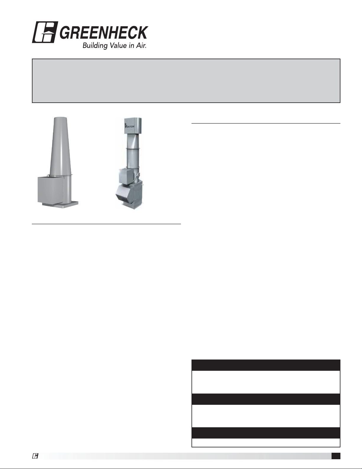
Model Vektor
®
Laboratory Exhaust System
-H and Vektor®-HS
Installation, Operation and Maintenance Manual
Please read and save these instructions for future reference. Read carefully before attempting to assemble,
install, operate or maintain the product described. Protect yourself and others by observing all safety
information. Failure to comply with instructions could result in personal injury and/or property damage!
Vektor®-H Vektor®-HS
General Safety Information
Only qualified personnel should install this fan system.
Personnel should have a clear understanding of these
instructions and should be aware of general safety
precautions. Improper installation can result in electric
shock, possible injury due to coming in contact with
moving parts, as well as other potential hazards. Other
considerations may be required if high winds or seismic
activity are present. If more information is needed,
contact a licensed professional engineer before moving
forward.
1. Follow all local electrical and safety codes, as well as
the National Electrical Code (NEC), the National Fire
Table of Contents
General Safety Information ......................1
Receiving / Unpacking / Handling / Storage .......2
Inspection and Maintenance during Storage .......2
Removing from Storage .......................3
General Information
Unit and System Identification ..................3
Pre-Installation Information ....................3
Electrical Disconnects ........................3
Moving Parts / Guards ........................3
Air Pressure and Suction ......................3
Lifting Information .............................4
Roof Curb and Mounting Details .................4
Duct Installation - Bottom Inlet ..................5
Side or End ...................5
Stack Extensions ..............................5
System Assembly .............................5
Kitchen Roof Mounting Installation ................6
Plenum Drainage Piping and Trap Detail ...........7
Electrical Connections .........................7
Variable Frequency Drive .......................8
Pre-Start-Up Checks ...........................8
Maintenance
Belts / Fasteners and Set Screws ...............9
Motors ....................................9
Fan Shaft Bearings ..........................9
Bearing Relubication Schedule ................10
Vektor-HS Nozzle Bearings ...................10
Damper Actuators ..........................10
Parts List and Assembly .......................11
Maintenance Log ......................Backcover
Our Commitment ......................Backcover
Protection Agency (NFPA), where applicable. Follow
the Canadian Electrical Code (CEC) in Canada.
2. The rotation of the wheel is critical. It must be free
to rotate without striking or rubbing any stationary
objects.
3. Motor must be securely and adequately grounded.
4. Do not spin fan wheel faster than maximum
cataloged fan rpm. Adjustments to fan speed
significantly effects motor load. If the fan RPM is
changed, the motor current should be checked to
make sure it is not exceeding the motor nameplate
amps.
5. Do not allow the power cable to kink or come in
contact with oil, grease, hot surfaces or chemicals.
Replace cord immediately if damaged.
6. Verify that the power source is compatible with the
equipment.
7. Never open access doors to a duct while the fan is
running.
DANGER
Always disconnect power before working on or near a
fan. Lock and tag the disconnect switch or breaker to
prevent accidental power up.
CAUTION
When servicing the fan, motor may be hot enough
to cause pain or injury. Allow motor to cool before
servicing.
CAUTION
Precaution should be taken in explosive atmospheres.
®
Vektor®-H and Vektor®-HS Laboratory Exhaust System
1
Page 2

Receiving
Greenheck model Vektor-H and Vektor-HS fans are
thoroughly inspected, test run at the factory, and
shipped on a skid or packaged to minimize damage
during shipment. The transportation carrier has the
responsibility of delivering all items in their original
condition as received from Greenheck. The individual
receiving the equipment is responsible for inspecting the
unit for obvious or hidden damage and recording any
damage on the bill of lading before acceptance of the
equipment. All claims (if necessary) shall be filed with
the final carrier.
Unpacking
Verify that all required parts and the correct quantity
of each item have been received, including accessory
kit containing gasketing, etc. If any items are missing,
report shortages to your local representative to arrange
for obtaining missing parts. Sometimes it is not
possible that all items for the unit be shipped together
due to availability of transportation and truck space.
Confirmation of shipment(s) must be limited to only
items on the bill of lading.
Handling
The Vektor-H and Vektor-HS laboratory exhaust system
is shipped in subassembly sections for easy rigging
and installation. Depending on the fan size, the sections
can include: Blower Assembly, Stack Extension, and
Discharge Nozzle.
The Vektor-H and Vektor-HS are designed to be selfsupporting and standing (without the use of guy wires)
when assembled per the instructions provided within
this manual. All subassembly sections have lifting lugs
as shown.
Storage
Fans are protected against damage during shipment. If
the unit cannot be installed and operated immediately,
precautions need to be taken to prevent deterioration of
the unit during storage. The user assumes responsibility
of the fan and accessories while in storage. The
manufacturer will not be responsible for damage during
storage. These suggestions are provided solely as a
convenience to the user.
INDOOR
The ideal environment for the storage of fans and
accessories is indoors, above grade, in a low humidity
atmosphere which is sealed to prevent the entry of
blowing dust, rain, or snow. Temperatures should
be evenly maintained between 30° and 110°F. (-1°C
and 43°C). Wide temperature swings may cause
condensation and “sweating” of metal parts. All
accessories must be stored indoors in a clean, dry
atmosphere.
Remove any accumulations of dirt, water, ice or snow
and wipe dry before moving to indoor storage. To avoid
“sweating” of metal parts allow cold parts to reach room
temperature. To dry parts and packages use a portable
electric heater to get rid of any moisture build up. Leave
coverings loose to permit air circulation and to allow for
periodic inspection.
The unit should be stored at least 3½ in. (89 mm) off the
floor on wooden blocks covered with moisture proof
paper or polyethylene sheathing. Aisles between parts
and along all walls should be provided to permit air
circulation and space for inspection.
OUTDOOR
Fans designed for outdoor applications may be stored
outdoors, if absolutely necessary. Roads or aisles for
portable cranes and hauling equipment are needed.
The fan should be placed on a level surface to prevent
water from leaking into the fan. The fan should be
elevated on an adequate number of wooden blocks so
that it is above water and snow levels and has enough
blocking to prevent it from settling into soft ground.
Locate parts far enough apart to permit air circulation,
sunlight, and space for periodic inspection. To minimize
water accumulation, place all fan parts on blocking
supports so that rain water will run off.
Do not cover parts with plastic film or tarps as these
cause condensation of moisture from the air passing
through heating and cooling cycles.
Fan wheels should be blocked to prevent spinning
caused by strong winds.
Inspection and Maintenance during
Storage
While in storage, inspect fans once per month. Keep a
record of inspection and maintenance performed; see
backcover.
If moisture or dirt accumulations are found on parts,
the source should be located and eliminated. At each
inspection, rotate the wheel by hand ten to fifteen
revolutions to distribute lubricant on motor and
bearings. If paint deterioration begins, consideration
should be given to touch-up or repainting. Fans with
special coatings may require special techniques for
touch-up or repair.
Machined parts coated with rust preventive coating
should be restored to good condition promptly if signs
of rust occur. Immediately remove the original rust
preventive coating with petroleum solvent and clean
with lint-free cloths. Polish any remaining rust from
surface with crocus cloth or fine emery paper and oil.
Do not destroy the continuity of the surfaces. Wipe
clean thoroughly with Tectyl® 506 (Ashland Inc.) or
the equivalent. For hard to reach internal surfaces or
for occasional use, consider using Tectyl® 511M Rust
Preventive or WD-40® or the equivalent.
Laboratory Exhaust System
2
®
Page 3
REMOVING FROM STORAGE
As fans are removed from storage to be installed in their
final location, they should be protected and maintained
in a similar fashion, until the fan equipment goes into
operation.
Prior to assembly and installation of the Vektor fan and
system components, inspect the fan assembly to make
sure it is in working order.
1. Check all fasteners, set screws on the fan, wheel,
bearings, drive, motor base and accessories for
tightness.
2. Rotate the fan wheel(s) by hand and assure no parts
are rubbing. Access to the wheel is obtained through
a bolted panel located on the side of the fan housing.
General Information
To ensure a successful installation, the instructions in
this manual should be read and adhered to. Failure to
comply with proper installation procedures may void the
warranty.
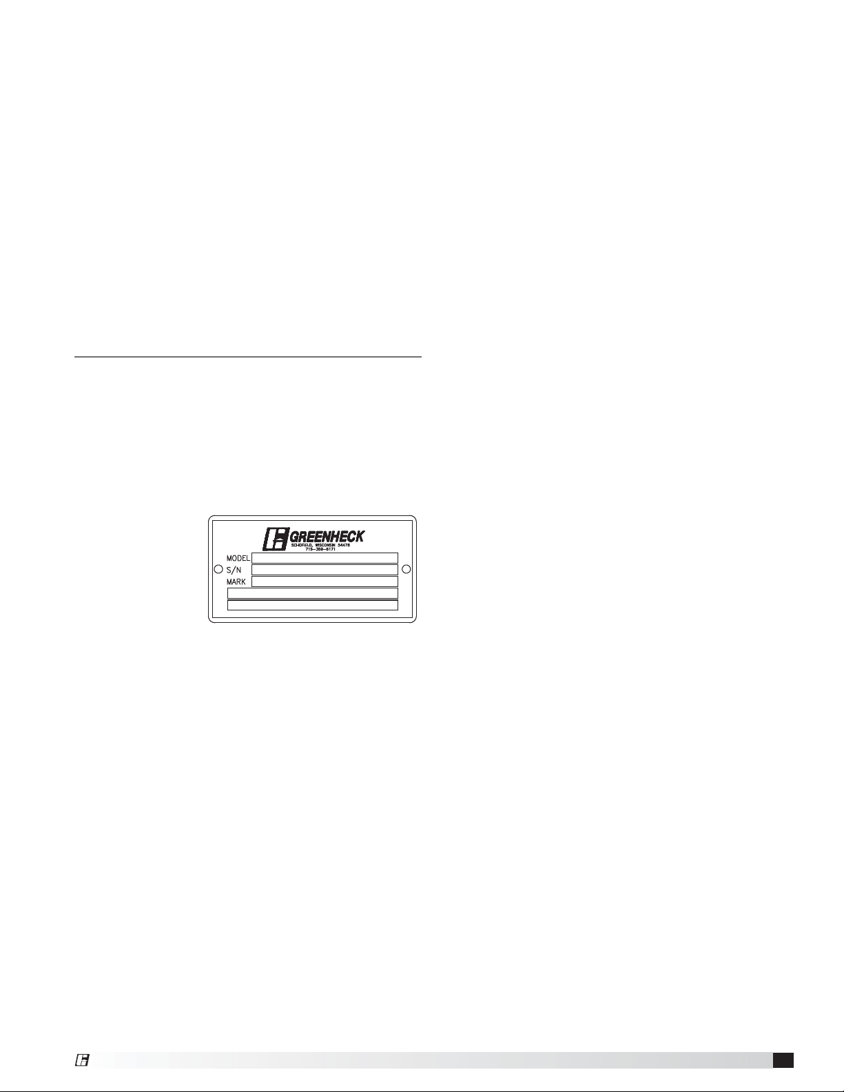
Unit and System Identification Tags
Each fan has a permanently affixed manufacturer’s
engraved metal nameplate containing the model
number and individual serial number.
The tag shown
is an example of
an identification
nameplate on the
fan. The information
provides general
details about
the fan, as well as containing specific information
unique to the unit. When contacting your Greenheck
representative with future needs or questions, please
have the information on this label available. Tags are
mounted in an area which is clearly visible, usually on
the side of the fan cabinet.
Vektor fan systems may arrive in component pieces
due to shipping restrictions. Individual components of a
system have matching identification tags which should
be used to identify and assemble the complete system.
Assembling systems with different identification tags
can cause reductions in the fan(s) performance.
Prior to fully assembling and installing the Vektor-H or
Vektor-HS fans, inspect bypass air plenums and the fan
assembly to make sure they are in working order.
Electrical Disconnects
All fan motors should have disconnects located in close
visual proximity to turn off electrical service. Service
disconnects shall be locked-out when maintenance is
being performed.
Moving Parts
All moving parts must have guards to protect personnel.
Refer to local codes for requirements as to the number,
type and design. Fully secure fan wheel before
performing any maintenance. The fan wheel may start
“free wheeling” even if all electrical power has been
disconnected. Before the initial start-up or any restart,
check the following items to make sure that they are
installed and secure.
t %POPUTQJOGBOXIFFMGBTUFSUIBOUIFNBYJNVN
cataloged fan rpm.
t "EKVTUNFOUTUPGBOTQFFETJHOJmDBOUMZBGGFDUTNPUPS
load. If the fan RPM is changed, the motor current
should be checked to make sure it is not exceeding
the motor nameplate amps.
Guards (Motor Cover, Weatherhoods)
Do not operate fans without proper protective devices in
place. Failure to do so may result in serious bodily injury
and property damage. Check local codes to ensure
compliance for all protective devices.
Air Pressure and Suction
In addition to the usual hazards associated with rotating
machinery, fans also create a dangerous suction at the
inlet. Special caution needs to be used when moving
around a fan, whether it is in operation or not. Before
start-up, make sure the inlet area is clear of personnel
and loose objects.
Pre-Installation Information
Before installation, it is important to be certain the
mounting surface will bear the operating weight of the
unit. For proper unit operation, it is also important that it
be operated in a completely level position.
For further details on safety practices involving
industrial and commercial fans, please refer to AMCA
Publication410.
®
Laboratory Exhaust System
3
Page 4
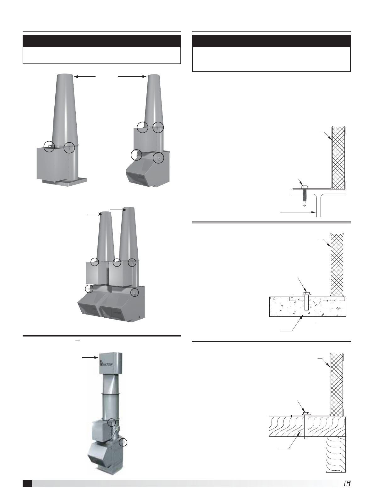
Lifting Information
Roof Curb and Mounting Details
CAUTION
The cone is to be lifted by the cone lifting lugs,
separately and individually from the fan assembly.
Vektor-H
Single Fan System
without Bypass Air Plenum
Cone
Lifting Lugs
Cone
Lifting Lugs
Unit
Assembly
Lifting Lugs
Cone
Fan
Single Fan System
with Bypass Air Plenum
Bypass
Air
Plenum
NOTE
Steel, concrete or wood roof support is per structural
engineer and in accordance with load requirements
and applicable building codes.
The figures below illustrates three common methods
used to install Vektor systems. Methods used to attach
a Vektor unit are dependent on local codes, roof
construction design and roof construction materials.
Consult an architect or structural engineer for proper
means of attachment.
Steel
Continuous weld or stitch weld.
Minimum 6 inch (152.4 mm) stitch weld by
3.25 inch (82.5 mm) spacing minimum.
Minimum 6 inch (152.4 mm) weld on each corner.
OR
Install 5/16 inch (7.9375 mm) 24 Dril-Flex® Self-Drilling
Tapping Screws. 3/16 inch (4.7625 mm) minimum thread
engagement into A36 steel, centered in flange.
4.5 inch (114.3 mm) spacing
5/8 inch (15.875 mm) minimum edge distance
ALL HARDWARE BY OTHERS
STEEL STRUCTURAL SUPPORT
(BY OTHERS, SEE NOTE ABOVE)
Greenheck Roof Curb GPFHL/GPFHD
Unit
Assembly
Lifting Lugs
Multiple Fan System with Bypass Air Plenum
Vektor-HS with SAVVE Technology
Cone
Lifting Lugs
Concrete
Greenheck Roof Curb GPFHL/GPFHD
Install 3/8 inch (9.525 mm) SS power wedge bolts
2.5 inch (63.5 mm) maximum spacing from curb corners
4.5 inch (114.3 mm) maximum bolt spacing
3.5 inch (88.9 mm) minimum embedment
4.5 inch (114.3 mm) minimum edge
distance centered in flange
ALL HARDWARE BY OTHERS
CONCRETE STRUCTURAL SUPPORT
(BY OTHERS, SEE NOTE ABOVE)
Greenheck Roof Curb GPFHL/GPFHD
Install 3/8 inch (9.525 mm) SS lag or thru-bolt with
1 inch (25.4 mm) O.D. washer
2.5 inch (63.5 mm) maximum spacing from curb corners
4.5 inch (114.3 mm) maximum bolt spacing
3.5 inch (88.9 mm) minimum tread engagement,
not including tapered tip
2 inch (50.8 mm) minimum edge distance,
centered in flange
Pre-drill holes 40-60% of lag diameter
ALL HARDWARE BY OTHERS
Laboratory Exhaust System
4
Unit
Assembly
Lifting Lugs
WOODEN STRUCTURAL SUPPORT
(BY OTHERS, SEE NOTE ABOVE)
®
Page 5

Duct Installation
System Assembly
Bottom Inlet Duct Connection
The end of the duct (customer-supplied) is secured
between the roof curb’s top edge and the curb cap of
either the Vektor-H or bypass air plenum. If an isolation
damper is present in the roof curb, the duct is located
between the roof curb and the damper adapter tray.
Option 1: t/PJTPMBUJPOEBNQFSJOSPPGDVSC
t#PUUPNJOMFUPOCZQBTTBJSQMFOVN
Vektor-H or Vektor-HS
Duct
Roof Curb
Option 2: t8JUIJTPMBUJPOEBNQFSJOSPPGDVSC
Vektor-H
Adapter Tray
Isolation Damper
Duct
Duct Connection to Curb
Side or End Duct Connection
t7FLUPS)PS7FLUPS)4
t8JUICZQBTTBJSQMFOVN
NOTE
When installing each section, be certain to rig each
section separately using the lifting lugs provided.
Gasket
Gasket
5/16 inch self-tapping screws
Gasket
5/16 inch self-tapping screws
Gasket
Bolt and Washer
Detail
NOTE
Plenum is provided with removable side or end
panels, allowing the proper duct connection.
Duct flange and
gasketing by
others
Bypass Air
Plenum
Roof Curb
Duct to Bypass Air Plenum
Stack Extensions
Systems with multiple stack extensions require all
sections assembled and installed on site between the
main fan body and the discharge cone. Each section
has guy wire attachment brackets located on the upper
end of each section. The order sections are installed
in are universal. Gasketing (3/16 x 1/2 inch with sticky
back) is provided and is to be installed between each
joining section.
Guy wires are required on system with multiple stack
extensions. Location of connections, wiring and
anchorage is determined by a structural engineer.
®
1. Mount roof curb to roof deck in accordance with
local codes.
2. Install 3/16-inch thick x 1/2-inch wide, closed-cell
gasket on the top edge of the curb, adhesive side
down (gasket provided). Leave no gaps between
gasket sections to ensure tight seal.
3. Place the bypass air plenum (BAP) onto the
previously installed gasket and secured roof curb.
If a BAP is not provided for the unit, skip to Step 5.
Pre-drill pilot holes into the roof curb and attach the
BAP to the roof curb with mounting hardware (by
others).
4. Install 3/16-inch thick x 1/2-inch wide, closed-cell
gasket on the top edge of BAP, adhesive side down
(gasket provided). Leave no gaps between gasket
sections to ensure a tight seal.
5. Place the curb cap of the fan housing onto the
gasket and BAP or onto roof curb if BAP is not
provided. Attach the curb cap using the provided
5/16-inch self-tapping screws. If a BAP is not
provided, pilot holes must be drilled into the roof
curb.
6. Install the final nozzle subassemblies as shown in the
submittal drawing. Align flange bolt holes and fasten
sections using the 316 stainless steel bolts, washers,
and lock washers provided.
7. Follow electrical connection and pre-start-up checks
as listed on pages 7 and 8.
Laboratory Exhaust System
5
Page 6

Kitchen Roof Mounting Installation
Grease
Trap
Welded duct
Roof Curb
Roof Deck
Typical Commercial Kitchen Installation
by others.
Minimum of
18 inches
(457 mm)
above roof
deck per
NFPA.
WARNING
In a kitchen exhaust application, do not use a speed
control or isolation damper.
NOTE
In a kitchen fan and high temperature applications
exhaust upblast fans must have external wiring.
Grease
Trap
UL/cUL 762 installation are for restaurant applications.
1. The size of the duct must be equal to the inlet
opening.
2. Secure the fan to curb at all four corners using a
minimum eight anchor bolts, lag screws or other
suitable fasteners.
3. Use optional grease trap and external junction box.
4. Area codes may require a continuous weld between
duct and inlet.
5. To comply with NFPA 96, the discharge is required
to be a minimum of 40 inches (1016 mm) above the
roof deck and a minimum of 10 ft. from any building
air intake. The minimum velocity in the duct should
be 500ft/min. or greater.
6. Ductwork to an upblast discharge exhaust fan is
constructed of carbon steel not less than 16 MSG
(1.6 mm) and extends a minimum of 18 inches
(457mm) above the roof surface.
7. Ensure that a minimum of 500 ft/min. of air velocity
through the fan is maintained per NFPA 96,
clause 8.2.1.1, 2008 edition and UL 762, Issue #5,
December 19, 2003, clause 6.2.
Grease Trap
A grease trap is an aluminum trap designed to collect
grease residue to avoid drainage onto roof surface. It
contains a built-in water separating baffle.
Instructions
1. Apply cover to grease trap. Install clip nuts to trap
over holes provided. Attach cover with two #10 - 24
x 1/2 fasteners.
2. Position the container under the grease drain so the
drain spout enters the cover approximately 1
1
⁄2 to
2in. (38-51 mm).
3. Locate and mark the container mounting holes on
the extended base or roof curb.
4. Drill 3/16 in. (5 mm) diameter holes in marked
locations.
5. Apply container with #10 - 24 x 3/4 fasteners.
6. For most climates, fill container with water (at
installation and after each cleaning) until it flows out
the drain hole. The unit is now ready for use.
Maintenance
Regular inspection of grease trap is recommended.
Depending on the amount of grease discharged through
the fan, the grease trap should be changed accordingly
to ensure proper operation.
Laboratory Exhaust System
6
®
Page 7

Plenum Drainage Piping / Trap
Detail (By Others)
Fan Drain
Connection
There is a location for a pipe connection on each tubular
fan housing and bypass air plenum. Each drain may
need to be connected to a drainage system to ensure
proper disposal of any water or condensate that may
occur.
t %SBJODPOOFDUJPOTBSFJODI/15
t *OTUBMMFEQJQJOHUPIBWFBEPXOXBSEBOHMFUPBMMPX
for drainage
t 'JMMUSBQTUPSFDPNNFOEFEMFWFMCFGPSFTUBSUVQ
Note: A conservative method of trap design is to set N
= total static pressure.
Positive Pressure Trap on Tubular Fan Housing
Connect
this end
to fan drain.
H/2 H/2
H
Plenum Drain
Connection
1.25 inch
minimum
N
for compatibility with the fan motor. In addition, the
supply wiring must be properly fused and conform to
local and national electrical codes. If the unit is supplied
with a safety disconnect switch, ensure proper wiring
to the fan motor. Be sure the disconnect is switched to
the “OFF” position before connecting supply wires. If
no disconnect is supplied, ensure the supply wire is not
live before connection. Supply wires are then connected
to the optional safety disconnect switch (if supplied) or
motor.
Vektor-H Motor Disconnect and Isolation Damper
Wiring Diagram
Disconnect is mounted to fan housing. Transformers are
mounted to bypass air plenum with damper actuator
motors. For systems that ship unassembled because
of physical size, this connection at disconnect from
transformers must be field-installed. Wires with conduit
and fittings are provided pre-connected to transformers.
Single Phase Layout
115/208/230/277 volt, single phase
DISCONNECT
115/208/230/277 volt
Single phase
LINE IN
MOTOR
115/208/230/277 volt
Single phase
Disconnect is mounted to fan housing
Optional transformer and isolation damper, refer to CAPS file selection
TRANSFORMER
208/230/277 volt, single phase
Transformers must be wired independent
from VFD control.
24/115 volt, single phase
isolation damper actuator motor
power open/spring close
Field Wiring
Factory Wiring
FAN ONFAN OFF
N = Negative fan pressure (inches W.C.)
H = N - (0.5 inches minimum)
Negative Pressure Trap on Bypass Air Plenum
1.25 inch minimum
N
H
FAN OFF
H/2
H/2
FAN ON
N = Negative fan pressure (inches W.C.)
H = N - (0.5 inches minimum
Electrical Connections
NOTE
Refer to the Vektor-HS SAVVE controls
Installation, Operation and Maintenance Manual
for electrical wiring and connection information.
Before electrical connections are made, the supply
voltage, phase and ampere capacity must be checked
DISCONNECT
208/230/460/575 volt
Three phase
DISCONNECT
208/230/460/575 volt
Three phase
Three Phase Layout
LINE IN
208/230/460/575 volt, three phase
Disconnect is mounted to fan housing
Optional transformer and isolation damper, refer to CAPS file selection
MOTOR
208/230/460/575 volt
60 cycle, three phase
Three Phase with
Variable Frequency Drives Layout
LINE IN
208/230/460/575 volt, three phase
VFD
supplied and wired
by others
Disconnect is mounted to fan housing
Optional transformer and isolation damper,
refer to CAPS file selection
MOTOR
208/230/460/575 volt
60 cycle, three phase
Field Wiring
Factory Wiring
TRANSFORMER
208/230/460/575 volt, single phase
Transformers must be wired independent
from VFD control.
24/115 volt, single phase
isolation damper actuator motor
power open/spring close
Field Wiring
Factory Wiring
TRANSFORMER (if required)
208/230/460/575 volt, single phase
Transformers must be wired independent
from VFD control.
24/115 volt, single phase
isolation damper actuator motor
power open/spring close
®
Laboratory Exhaust System
7
Page 8

Vektor-H Applications with Variable
Frequency Drive (VFD)
For Vektor systems with single-point, three-phase
wiring per blower, the isolation damper actuator will be
powered via a step-down transformer, which is wired to
the fan disconnect, as shown in the wiring diagrams on
page 7.
If fan flow (motor speed) is to be controlled using a
variable frequency drive with this wiring, the reduced
voltage and frequency supplied to the fan will cause
control problems with the isolation damper actuator.
When a project’s Vektor control sequence requires
the use of a VFD, it is suggested that the control
contractor supply the isolation damper actuator voltage,
independent of the power supplied to the Vektor fan
motor.
NOTE
For Vektor-HS fans provided from the factory with
a VFD, refer to the Vektor-HS SAVVE controls
Installation, Operation and Maintenance Manual
for electrical wiring and connection information.
Pre-Start-Up Checks
Check all fasteners for tightness.
Check radial gap, overlap and wheel alignment. The
wheel should be aligned as shown. Although the wheel
position is preset and the unit is test run at the factory,
movement may occur during shipment.
The radial gap should be consistent at all locations
between the centrifugal wheel and the inlet cone.
Centering may be accomplished by loosening the inlet
cone bolts and repositioning the inlet cone.
To obtain the optimum performance, the centrifugal
wheel must overlap the inlet
cone. Adjustments can be
made by loosening the set
screws in the wheel and
A
moving the wheel to the
desired position.
Wheel rotation should
be in the same direction
as the rotation decal affixed to the unit. (Clockwise
rotation is correct as viewed from fan inlet). For 3-phase
installations, fan rotation can be reversed by simply
interchanging any two of the three electrical leads. For
single phase installations, follow the wiring diagram
located on the motor.
Wheel
Inlet
Cone
Overlap
Radial Gap
NOTE
Any increase in fan speed represents a substantial
increase in horsepower required from the motor.
Always check motor load amperage and compare to
nameplate rating when changing fan speed.
Unit
Size
9 3 3/16 ± 1/8 81 ± 3
10 3 7/16 ± 1/8 87 ± 3
12 4 ± 1/8 102 ± 3
13 4 7/16 ± 1/8 113 ± 3
16 5 7/16 ± 1/8 138 ± 3
18 6 3/8 ± 1/8 162 ± 3
22 7 13/16 ± 3/16 198 ± 5
24 8 5/8 ± 1/4 219 ± 6
30 10 9/16 ± 3/8 268 ± 10
36 12 3/4 ± 3/8 324 ± 10
± Tolerance (in.)
Inlet Cone to Backplate
A Dimension
A Dimension
± Tolerance (mm)
Radial Gap is adjusted by loosening the inlet cone
bolts and centering the cone on the wheel. If additional
adjustment is required to maintain a constant radial gap,
loosening the bearing bolts and centering the wheel is
acceptable as a secondary option.
Overlap or offset, is adjusted by loosening the wheel
hub from the shaft and moving the wheel to the desired
position along the shaft. The transition between the inlet
cone and wheel should be as shown; there is a smooth
feel to the profile when moving from one component to
the other.
Laboratory Exhaust System
8
®
Page 9

Maintenance
WARNING
Disconnect all electrical power to the fan and secure
to the ‘OFF’ position prior to inspection or servicing.
Failure to comply with this safety precaution could
result in serious injury or death.
Once the fan has been put into operation, a periodic
maintenance program should be set up to preserve
the reliability and performance of the fan. Items to be
included in this program are:
t #FMUT t 3FNPWBMPGEVTUBOEEJSU
t 'BTUFOFST t 'BOTIBGUCFBSJOHT
t 4FU4DSFXT t 7FLUPS)4OP[[MFCFBSJOHT
t .PUPST t 3FMVCJDBUJPOTDIFEVMF
Belts
Premature belt failures are frequently caused by
improper belt tension (either too tight or too loose) or
misaligned pulleys. The proper tension for operating a
V-belt is the lowest tension at which the belts will not
slip at peak load conditions. For initial tensioning, the
proper belt deflection
half-way between pulley
Deflection =
64
Belt Span
centers is 1/64 inch for
each inch of belt span.
For example, if the belt
span is 64 inches, the
belt deflection should be
one inch using moderate
Belt Span
thumb pressure at
midpoint of the drive.
Belt Tension
Check belt tension two times during the first 24 hours
of operation and periodically thereafter. To adjust belt
tension, simply loosen four fasteners (two on each side
of the motor plate) and slide the motor plate away from
the fan shaft until proper belt tension is attained. On
some fans, fasteners attaching the motor to the motor
plate must be loosened in order to adjust
the belt.
It is very important that the drive
pulleys remain in proper alignment
after adjustments are made.
Misalignment of pulleys will result
in premature belt wear, noise,
vibration and power loss.
Belt
Alignment
Fasteners and Set Screws
A periodic inspection should include checking all
fasteners and set screws for tightness. Particular
attention should be paid to set screws attaching the
wheel to the shaft.
Motors
Many fractional horsepower motors installed on the
smaller fans are lubricated for life and require no further
attention. Motors supplied with grease fittings should be
greased according to directions printed on the motor.
Removal of Dust and Dirt
Dirt clogs cooling openings on the motor housing,
contaminates bearing lubricant, and collects on the
impeller causing severe imbalance if left unchecked.
The exterior surface of the motor and impeller should be
thoroughly cleaned periodically. Use caution and do not
allow water or solvents to enter the motor or bearings.
Under no circumstances should motors or bearings be
sprayed with steam or water.
Fan Shaft Bearings
The bearings for Greenheck fans are carefully selected
to match the maximum load and operating conditions
of the specific class, arrangement, and fan size. The
instructions provided in this manual and those provided
by the bearing manufacturer will minimize any bearing
problems. Bearings are the most critical moving part
of the fan; therefore, special care is required when
mounting them on the unit and maintaining them.
Locking collars and set screws, in addition to fasteners
attaching the bearing to the bearing plate must be
checked for tightness. Greenheck Fan Corporation
recommends bearings to be relubricated quarterly at a
minimum. All Vektor-H and Vektor-HS fans use Mobil
Mobilith SHC 100 synthetic grease conforming to
NCGI Grade 2. Never mix greases made with different
bases as this will cause a breakdown of the grease and
possible failure of the bearing. For specific information,
contact the factory representative or the fan system
submittals.
t 'PSDPOEJUJPOTJODMVEJOHUFNQFSBUVSFTNPJTUVSF
dirt or excessive vibration, consult the factory for a
specific lubrication interval for your application.
t -VCSJDBOUTIPVMECFBIJHIRVBMJUZMJUIJVNDPNQMFY
synthetic grease conforming to NLGI Grade 2.
t 5IFVTFPGOPOTZOUIFUJDHSFBTFXJMMEFDSFBTF
lubrication intervals by approximately 3 times.
t 4UPSBHFQFSJPETPGNPOUITPSMPOHFSSFRVJSF
monthly rotation of the shaft and purging grease
prior to storage and start-up.
®
Laboratory Exhaust System
9
Page 10

Recommended Bearing Lubrication Schedule
Relubrication Schedule in Months*
Fan Size 9 - 13 16 - 22 24 30 - 36
Fan
RPM
1
⁄2 - 1 11⁄8 - 11⁄2 15⁄8 - 17⁄8 115⁄16 - 23⁄16
Bearing Bore (inches)
to 250 12 12 12 12
500 12 12 12 12
750 12 12 12 12
1000 12 12 12 12
1250 12 12 12 12
1500 12 12 12 10
2000 12 10 8 6
2500 12 7 5 4
3000 12 5 3 2
3500 12 3 2 0.75
4000 12 2 0.5
5000 12 1
Number
of shots of
48810
grease**
* Lubrication interval is based on 12 hour per day operation and
maximum 160°F. housing temperature. For 24 hour per day
operation, the interval should be cut in half.
** Lubricant should be added with the shaft rotating and until clean
grease is seen purging from the bearing. The lubrication interval
may be modified based on the condition of the purged grease.
If bearing is not visible to observe purged grease, lubricate with
number of shots indicated for bore size.
Vektor-HS Nozzle Bearings
The bearings for the HS nozzle assembly are
permanently lubricated and do not require additional
grease.
Damper Actuators
Damper actuators, when supplied by manufacturer,
are designed to be maintenance free. No lubrication is
required.
Laboratory Exhaust System
10
®
Page 11

Vektor-H and Vektor-HS Exhaust Fan Parts List and Assembly
Each fan bears a manufacturer’s nameplate with model number and serial number embossed. This information in
addition to the parts list shown, will assist the local Greenheck representative and the factory in providing service
and replacement parts.
Side View
Motor
Pulley
Belt Belt Tube
Shaft Pulley
Top View
Bearing Cover
Bearings
Shaft
Motor
Wheel
Inlet Cone
(venturi)
Vektor-HS Nozzle Parts List and Assembly
7
3
4
15
18
16
17
11
1
10
6
13
8
9
12
19
14
20
5
2
Bearing Support
Motor Cover
(optional)
Motor Mounting
Plate
Item Quantity Description
1 2 Transition Weld
2 2 Transition side cover
3 2 Wind wrap round
4 2 Wind wrap flat
5 2 Frame bottom bar
6 2 Frame top bar
7 2 Frame weld
8 2 Blade weld
9 1 or 2* Actuator mount
10 4 Lifting lug
11 1 or 2* Actuator cover
12 2 Blade seal, right
13 6 Blade seal, left
14 4 Flex backing
15 2 Vektor backing
16 1 or 2* Actuator
17 1 Electrical box
18 4 Bearing
19 4 Blade seal
20 2 Flex seal
* Quantity 1 for sizes 9 thru 13
Quantity 2 for sizes 16 thru 36
®
Laboratory Exhaust System
11
Page 12

Maintenance Log
Date ___________________Time _____________ AM/PM
Notes: ___________________________________________
_________________________________________________
_________________________________________________
_________________________________________________
_________________________________________________
Date ___________________Time _____________ AM/PM
Notes: ___________________________________________
_________________________________________________
_________________________________________________
_________________________________________________
_________________________________________________
Date ___________________Time _____________ AM/PM
Notes: ___________________________________________
_________________________________________________
_________________________________________________
_________________________________________________
_________________________________________________
Date ___________________Time _____________ AM/PM
Notes: ___________________________________________
_________________________________________________
_________________________________________________
_________________________________________________
_________________________________________________
Date ___________________Time _____________ AM/PM
Notes: ___________________________________________
_________________________________________________
_________________________________________________
_________________________________________________
_________________________________________________
Date ___________________Time _____________ AM/PM
Notes: ___________________________________________
_________________________________________________
_________________________________________________
_________________________________________________
_________________________________________________
Date ___________________Time _____________ AM/PM
Notes: ___________________________________________
_________________________________________________
_________________________________________________
_________________________________________________
_________________________________________________
Date ___________________Time _____________ AM/PM
Notes: ___________________________________________
_________________________________________________
_________________________________________________
_________________________________________________
_________________________________________________
Our Commitment
As a result of our commitment to continuous improvement, Greenheck reserves the right to change specifications
without notice.
Specific Greenheck product warranties are located on greenheck.com within the product area tabs and in the
Library under Warranties.
(SFFOIFDL7FLUPS)BOEUIF7FLUPS)4XJUI4"77&
5FDIOPMPHZDBUBMPHTQSPWJEFBEEJUJPOBMJOGPSNBUJPOEFTDSJCJOH
UIFFRVJQNFOUGBOQFSGPSNBODFBWBJMBCMFBDDFTTPSJFTBOE
TQFDJmDBUJPOEBUB
".$"1VCMJDBUJPO4BGFUZ1SBDUJDFTGPS6TFSTBOE
*OTUBMMFSTPG*OEVTUSJBMBOE$PNNFSDJBM'BOTQSPWJEFT
BEEJUJPOBMTBGFUZJOGPSNBUJPO5IJTQVCMJDBUJPODBOCFPCUBJOFE
GSPN".$"*OUFSOBUJPOBM*ODBUXXXBNDBPSH
®
1IPOFt'BYt&NBJMHGDJOGP!HSFFOIFDLDPNt8FCTJUFXXXHSFFOIFDLDPN
t7FLUPS®)BOE7FLUPS®)43FW4FQUFNCFS $PQZSJHIUª(SFFOIFDL'BO$PSQPSBUJPO
12
 Loading...