

Part Number 462721
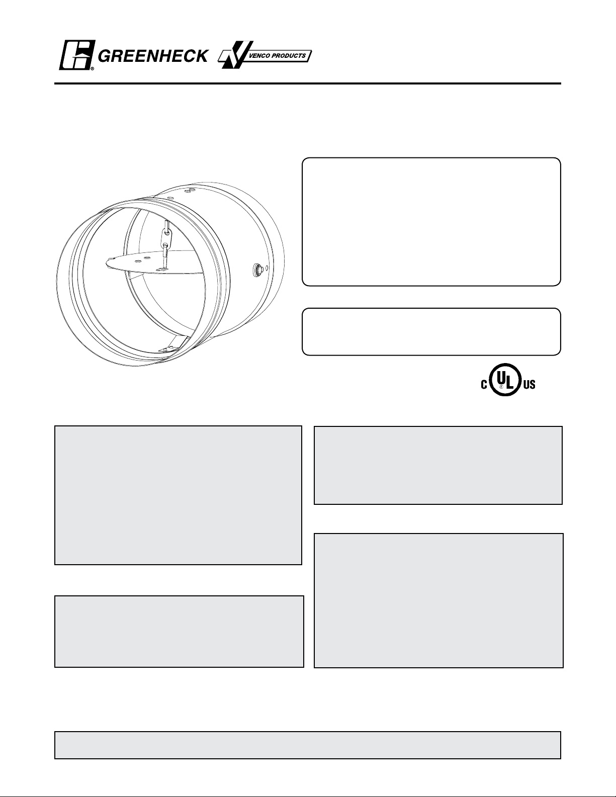
DFDR-XXX, SSDFDR-XXX,
FDR-XXX, and SSFDR-XXX MODELS
1 1⁄2 Hour Round Fire Dampers
Vertical and Horizontal Mount
Installation, Operation and Maintenance Instructions
DFDR-XXX, SSDFDR-XXX, FDR-XXX, and SSFDR-XXX
Model Dampers are intended for installation in accordance
with fire damper requirements established by:
National Fire Protection Association
NFPA Standards 80, 90A, & 101
BOCA National Building Codes
ICBO Uniform Building Codes
IBC International Building Codes
SBCCI Standard Building Codes
New York City (MEA listing #260-91-M)
“UL CLASSIFIED (see complete marking on product)”
“UL CLASSIFIED to Canadian safety standards (see
complete marking on product)”
UL Standard 555 (Classification #R13317)
RECEIVING AND HANDLING
Upon receiving dampers, check for both obvious
and hidden damage. If damage is found, record all
necessary information on the bill of lading and file
a claim with the final carrier. Check to be sure that
all parts of the shipment, including accessories, are
accounted for.
Dampers must be kept dry and clean. Indoor storage
and protection from dirt, dust and the weather is highly
recommended. Do not store at temperatures in excess
of 100°F (37°C).
INSTALLATION SUPPLEMENTS
Refer to the appropriate Greenheck installation
supplements for special rquirements:
• Steel Deck Supplement
Due to continuing research, Greenheck reserves the right to change specifications without notice.
SAFETY WARNING:
Improper installation, adjustment, alteration,
service or maintenance can cause property
damage, injury or death. Read the installation,
operating, and maintenance instructions thoroughly
before installing or servicing this equipment.
WARRANTY
Greenheck warrants this equipment to be free from
defects in material and workmanship for a period of one
year from the purchase date. Any units or parts which
prove to be defective during the warranty period will
be repaired or replaced at our option. Greenheck shall
not be liable for damages resulting from misapplication
or misuse of its products. Greenheck will not be
responsible for any installation or removal costs.
Greenheck will not be responsible for any service work
or backcharges without prior written authorization.
This manual is the property of the owner, and is required for future maintenance. Please leave it with the owner when
the job is complete.
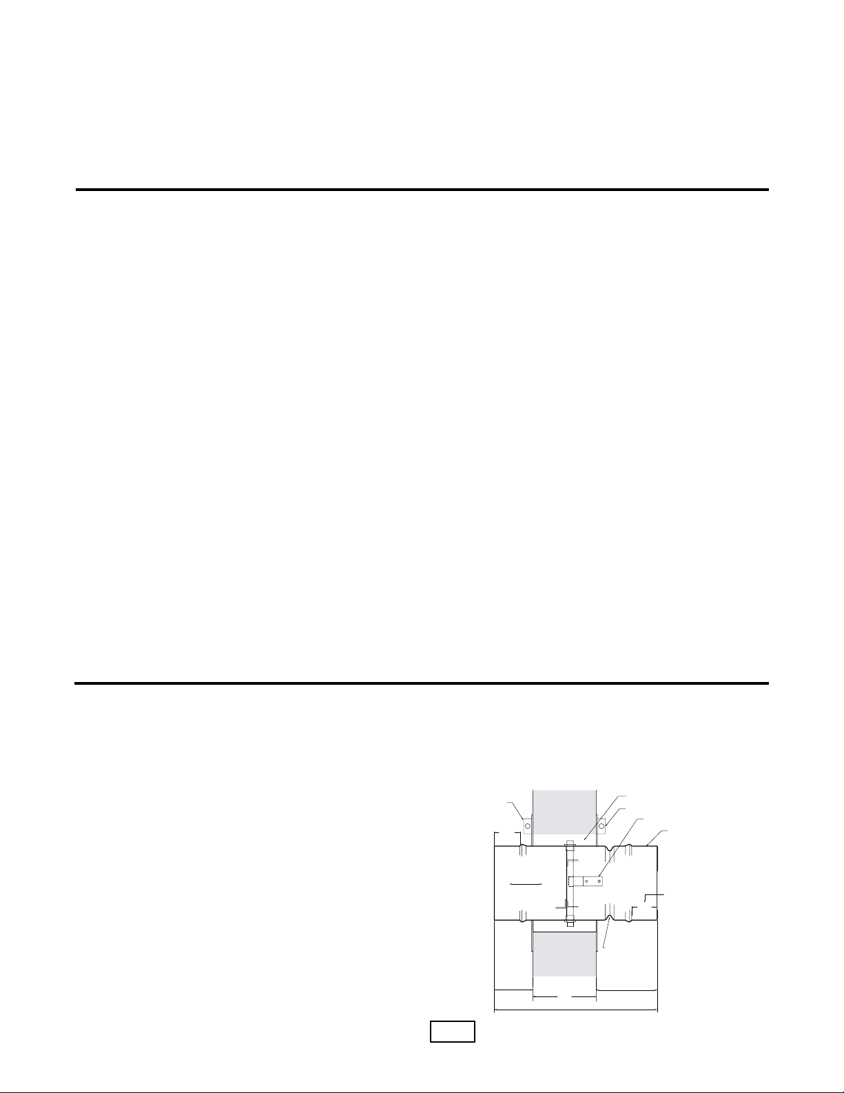
2 in.
TW
AIRFLOW
SLEEVE LENGTH
2 in.
6 in. max.6 in. max.
(OPTIONAL)
RETAINER PLATE
DUCT CONNECTION
AREA
CLEARANCE FOR
EXPANSION
RETAINER PLATE
BLADE LATCH
ACCESS DOOR TO BE ON
SAME SIDE AS BLADE LATCH
DUCT CONNECTION
AREA
DO NOT PLACE RETAINER
PLATE IN THIS GROOVE
Table of Contents
Pre-Installation Guidelines ...................................................................................2
Installation .........................................................................................................2-4
Maintenance .........................................................................................................4
Troubleshooting ....................................................................................................4
Pre-Installation Guidelines
The basic intent of a proper installation is to secure the fire damper in the opening in such a manner as to prevent
distortion and disruption of damper operation. This is accomplished by allowing the fire damper in rated separation
openings to expand and for the connecting duct to separate in the event of the collapse of the hanging system. The
following items will aid in completing the damper installation in a timely and effective manner.
1) Check the schedules for proper damper locations within the building. Visually inspect the damper for damage and
verify that the fusible link is in place or has not separated. Dampers will be supplied with a temperature responsive
fusible link device. If fusible link is not present or has separated, replace link. Never install a fire damper without the
proper UL approved fusible link in place.
2) Lift or handle damper using the frame. Do not lift damper using blades.
3) Do not install screws into the main body area of the damper frame as screws may interfere with and prevent damper
blade from opening and/or closing.
4) Damper must be installed into duct or opening free of distortion or other misalignment. Damper must not be
squeezed or stretched into duct or opening. Out of round, racked, twisted or misaligned installations can cause
torque requirements to exceed damper design.
5) Damper must be kept clean and protected from dirt, dust and other foreign materials prior to and after installation.
Examples of such foreign materials include but are not limited to: 1) Mortar dust 2) Drywall dust 3) Firesafing
materials 4) Wall texture and 5) Paint overspray.
6) Damper should be sufficiently covered to prevent overspray if wall texturing or spray painting will be performed
within 5 feet of the damper. Excessive dirt or foreign material deposits on damper can cause torque requirements to
exceed damper design.
7) Caulking is not allowed between the damper sleeve and the wall or floor opening (annular space). However, caulking
may be applied to the retaining plates and a field-applied sealant may be required for the damper sleeve and
transitions to meet certain duct leakage standards.
8) ACCESS: Suitable access (such that fusible links can be maintained) must be provided for damper inspection
and servicing. Where it is not possible to achieve sufficient size access, it will be necessary to install a removable
section of duct. (Refer to NFPA 90A).
9) The Code Authority Having Jurisdiction (AHJ) must evaluate and provide approval of final installation where
variations to these instructions are necessary.
Installation - Failure to follow these instructions will void all warranties.
These instructions apply to 11/2 hour rated fire dampers mounted (blades must be horizontal) in: 1) masonry, block or stud
walls and 2) concrete floors or ceilings. Specific requirements in these instructions are mandatory. Dampers must be installed
in accordance with these instructions to meet the requirements of UL 555. The installation of the damper and all duct
connections to the damper sleeve shall conform to the latest editions of NFPA 90A, Standard for the Installation of Air
Conditioning and Ventilating Systems, and the SMACNA Fire, Smoke and Radiation Damper Installation Guide, and UL
Classifications R13317.
1. CLEARANCES REQUIRED BETWEEN FIRE
DAMPER SLEEVES AND WALL/FLOOR
OPENINGS
Fire damper assemblies expand during periods of
intense heat. Therefore, it is essential that openings in
walls or floors be larger than the fire damper assembly
to allow for this expansion. The wall/floor opening
must be a minimum of
outside diameter of the damper. Refer to Section 4 for
additional installation considerations.
2
7
/8 in. (22mm) larger than the
Fig. 1

IN THIS GROOVE.
RETAINER PLATE
DO NOT PLACE
IN THIS GROOVE.
DO NOT PLACE
RETAINER PLATE
DAMPER FRAME
DAMPER FRAME
WOOD
STUD
MIN
1.00
STUD
METAL
1.00
MIN
Installation - Continued
Opening + 2 in. Min.
Wa ll/Floor Opening
= Nominal Size + 7/8 in. Min.
1.00 in. Ty p.
Fasteners
Clamping
Screw
Opening + 2 in. Min.
Fasteners
Clamping
Screw
Nut
Retaining
Plate Assembly
Clamping Screw
2. SLEEVE LENGTH AND WALL/FLOOR
THICKNESS
Insert the damper assembly into the prepared opening,
to appropriate depth (see page 2, Fig. 1).
Recommended maximum and minimum insertion depth
can be exceeded as long as the
C
of the damper
L
blade remains within the plane of the wall/floor.
IMPORTANT SAFETY DANGER! To avoid causing
death or serious bodily harm to building occupants, do
not insert screws into the damper frame unless used
for duct connection within 2 in. (51mm) of the frame
end.
The sleeve may extend a maximum of 6 in. (152mm)
beyond both sides of the wall or floor. Recommended
standard sleeve lengths for various wall/floor
thicknesses are:
Wall/Floor Thickness
Dimension (T
Inches (mm)
)
w
Up to 6½ (165) 13 5/8 (346)
6½ - 8½ (165 - 216) 15 5/8 (397)
8½ - 10½ (216 - 267) 17 5/8 (448)
Sleeve Length
Dimension (L)
Inches (mm)
3. DUCT TO SLEEVE CONNECTIONS
Dampers are supplied with sleeves from the factory
and can be installed without the need for additional
field installed sleeves.
Gauge of factory furnished sleeve determines the
type of duct to sleeve connections required (see table
below). Any duct connection other than the breakaway
connections are considered rigid.
• Place the damper and attached retainer plate into the
wall/floor opening.
• If a second retaining plate is being used, secure it on
the opposite side of the wall/floor
DO NOT POSITION RETAINER PLATE(S) IN
FRAME GROOVE
• Verify position, blade orientation, and actuator
clearance then tighten the retainer plate clamping
screws. The retainer plate(s) must overlap the wall/
floor opening a minimum of 1 inch (25mm). Secure
the retainer plate(s) to the wall using appropriate
fasteners (minimum #8 sheet metal screws) at the
four corners of each retainer plate when two retainer
plates are used and also within ¾ in. (19mm) of the
center of each plate when one retainer plate is used.
Fig. 2
Sleeve Gauge
(mm)
Duct Dimension
Maximum
Inches (mm)
Type of Duct to
Sleeve Connection
Permitted
10 ga. (3.5)
24 (610) Rigid or Breakaway14 ga. (2)
16 ga. (1.5)
20 ga. (1mm) 24 (610) Breakaway only
Sleeve thickness must not be less than the gauge of the
connecting duct.
UL Standard 555 requires all ducts to terminate at fire damper
sleeves.
4. SECURING THE DAMPER/SLEEVE ASSEMBLY
TO WALL AND FLOOR OPENINGS
Damper assemblies must be installed in wall/floor
openings using a single retaining plate on either side
of the wall/floor or by using a retaining plate on both
sides of the wall/floor. The use of a second retaining
plate is allowed, but is not necessary. A single retaining
plate is provided with the dampers. A second retaining
plate can be ordered as an option.
• The retaining plate(s) will open up for easy installation
when the clamping screw is loosened. If necessary,
remove the clamping screw and nut (see Fig. 2).
(IMPORTANT: The clamping mechanism should
face away from the wall/floor). Retainer plate(s) are
designed to mount flush to the wall/floor and hold the
damper in the wall/floor opening.
5. Recommended Preparation of Openings in
Wood and Metal Stud Walls
• Frame wall openings as shown below. (see Fig. 3)
• Double vertical studs are not required for openings
36 in. x 36 in. (914mm x 914mm) or smaller.
• Gypsum wall board must be fastened 12 in. (305mm)
on center to all stud and runner flanges surrounding
opening. (see Fig. 4)
• All construction and fasteners must meet the
requirements of the appropriate wall design (See UL
Fire Resistance Directory) and/or local codes.
Fig. 3
3

JO
JOPD
.BYJNVN
'MPPS3VOOFS
JO
$FJMJOH3VOOFS
1BOIFBE
4DSFXT
JOPD
.BYJNVN
NFUBMTUVET
JOPD
.BYJNVN
NFUBMTUVET
JOPD
.BYJNVN
XPPETUVET
JOPD
.BYJNVN
XPPETUVET
JO
6. Round Duct Connections
Round duct connections shall be attached
with #8 sheet metal screws as follows:
• Ducts 22 in. (559mm) dia. and smaller shall have three
screws.
• Ducts larger than 22 in. (559mm) dia. and up to
including 24 in. dia. shall have five screws.
NOTE: All breakaway connections described may
have duct sealant, PA2084T Duct Sealant Adhesive
manufactured by Precision or DP1010 Water Base Duct
Sealant manufactured by Design Polymetrics, applied
in accordance with SMACNA recommendations.
DFDR-XXX Blade Orientation
Fig. 4
Axle
30°
Axle
30°
Axle
30° Off Horizontal
(Maximum)
30° Off Horizontal
(Maximum)
Normal
Damper Maintenance
Dampers do not typically require maintenance as long as they are kept dry and clean. If cleaning is necessary, use mild
detergents or solvents. If lubrication is desired for components such as axle bearings, do not use oil-based lubricants
or any other lubricants that attract contaminants such as dust.
Dampers must be maintained, cycled, and tested at intervals not less than every six months and in accordance with the
latest editions of NFPA 90A & 92A, UL864 and local codes.
Damper Troubleshooting
The following is a possible cause and correction list for common concerns with the dampers.
Symptom Possible Cause Corrective Action
Frame is out of round causing blades to
Adjust frame such that it is round
interfere with frame
close
Screws interfere with blade Locate screws and remove
Contaminants on damper Clean with a non-oil based solvent (see
Damper Maintenance)
Link separated Heat Replace link
Damper does not fully open and/or fully
4
Copyright © 2006 Greenheck Fan Corporation
462721 DFDR-XXX FS Rev. 4 December 2006
 Loading...