

Page 1
®
READ AND SAVE THESE INSTRUCTIONS
Model SP/CSP-A700
Ceiling Exhaust and Inline Fans
PN 464238
Installation, Operation and Maintenance Manual
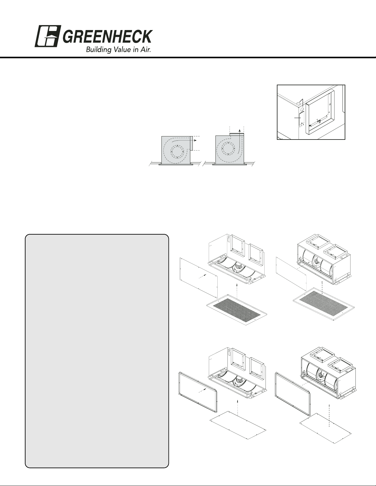
Prepare the Fan
1. Remove either top or side wiring knockout, depending on wiring direction, by
bending it back and forth to break tabs, shown in Fig. 1.
2. Check ductwork to see if the
fan’s discharge requires rotation
from horizontal to vertical
discharge, shown in Fig. 2.
3. To rotate from horizontal to vertical discharge, remove the eight screws holding the cover panel as
shown in Fig. 3a (for the CSP model remove the eight collar screws as shown in Fig. 4a). Then rotate
the fan housing so the discharge is facing up, shown in Fig. 3b. Replace the cover panel as shown in
Fig. 3b and replace the screws (for the CSP model attach the collar and its screws as shown in Fig. 4b).
Fig. 4a
WARNING !
To reduce the risk of fire, electric shock, or injury to
persons, observe the following:
• If a speed controller is used, this fan should only
be used with fan speed control, manufactured by
KB Electronics, Inc.
• Before servicing or cleaning unit, switch power off
at service panel and lock service disconnecting
means to prevent power from being switched on
accidentally. When the service disconnecting means
cannot be locked, securely fasten a prominent
warning device, such as a tag, to the service panel.
• Installation work and electrical wiring must be
done by qualified person(s) in accordance with all
applicable codes and standards, including firerated construction.
• The combustion airflow needed for safe operation
of fuel burning equipment may be affected by this
unit's operation. Follow the heating equipment
manufacturer’s guideline and safety standards
such as those published by the National Fire
Protection Association (NFPA), and the American
Society for Heating, Refrigeration and Air
Conditioning Engineers (ASHRAE), and the local
code authorities.
• When cutting or drilling into wall or ceiling, do not
damage electrical wiring or other hidden utilities.
• Ducted fans must always be vented to the
outdoors.
• For general ventilating use only. Do not use to
exhaust hazardous or explosive materials and
vapors.
• These fans are not recommended for cooking
exhaust applications. They are designed primarily
for low temperature, clean air applications only.
1
Fig. 1
Knockouts
Electrical
Access
Panel
Airflow
Airflow
Fig. 2
Fig. 3a
Fig. 3b
Fig. 4b
Access
Panel
Access
Panel
Access
Panel
Access
Panel
Collar
Collar
Page 2
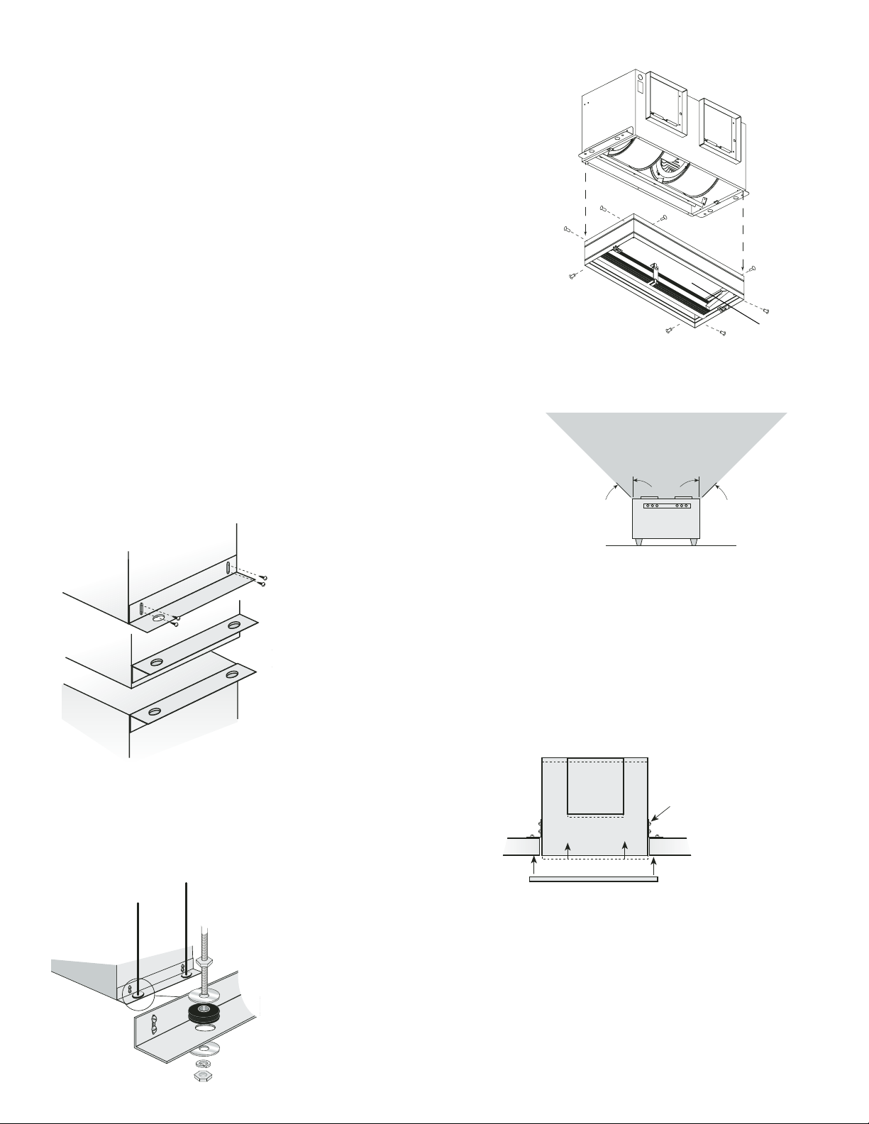
1. If fan is to be used in a fire resistive membrane ceiling, a
ceiling radiation damper must be used. Otherwise,
proceed to Install the Fan.
2. If the ceiling radiation damper is already mounted to the
fan from the factory, proceed to Install the Fan.
3. To mount the ceiling radiation damper to fan, make sure
grille attachment tabs are facing down. Then place the
inlet part of the fan into the ceiling radiation damper collar,
and use self-tapping sheet metal screws (by others) to
screw through the damper collar and into the fan housing,
shown in Fig. 5.
2
Install the Fan
Installation Recommendations
1. For best performance, choose a location with the shortest possible
duct run and minimum number of elbows. Do not mount near cooking
equipment. Fig. 7 shows the minimum distance these fans should be
placed in relation to cooking equipment.
2. Attach adjustable mounting brackets to fan, but leave the screws
loose until proper height is determined, shown in Fig. 8. For fan
only opening, cut 23
3
⁄4 x 113⁄4 inch hole in ceiling. For fan/CRD
combination opening only, cut 241⁄8 x 121⁄4 inch hole in ceiling.
For Frame Construction: Position unit between joists.
Position brackets such that bottom edge of housing will be
flush with finished ceiling, and tighten the adjustable mounting
brackets, shown in Fig. 9.
Fig. 7
Fig. 8
Fig. 9
Fig. 10
For Hanging Installations: Use Greenheck’s optional vibration isolator kit
Part Number VI Kit. Using the fan’s standard adjustable mounting brackets
and 10 by 32 threaded rod (by others), hang unit as shown in Fig. 10.
Ceiling Radiation Damper - CRD
Fig. 5
Do not allow
interference in
this area.
Brackets can be
used in either
position to adapt to
most mounting
Bottom Mount
situations
Bottom Mount
Top Mount
Do not install
fan in this area
45º
Slots in the
brackets
allow fine
adjustment
for flush
fit with
wall/ceiling
opening
45º
Page 3

4. Slide ductwork over the fan’s discharge collar and securely
attach it with sheet metal screws. Make sure the screws do
not interfere with damper operation. Check damper to make
sure it opens freely.
3
Wire the Fan
1. Remove wiring cover. Then wire unit to the correct installation type,
shown in Fig. 12, using proper wire connectors.
Attach the Grille
1. Attach grille with two screws provided, shown in Fig. 13. Make sure
not to over tighten, over tightening will damage grille.
2. Turn on power and check fan operation.
Fig. 13
Fig. 12
2. Push all wiring into the unit’s cover and replace wiring cover.
3. Installation of ductwork is critical to the performance of
the fan, shown in Fig. 11. Straight ductwork (1) or
ductwork that turns in the same direction as the wheel (2)
is recommended. Ductwork turning opposite the wheel
direction (3) will cause turbulence and back pressure
resulting in poor performance.
AIR FLOW
1
(GOOD)
3
(POOR)
2
(GOOD)
Fig. 11
Installation Recommendations
Install the Fan - Continued
Black wire is “Hot”
White wire is “Neutral”
Green wire is “Ground”
Page 4

Warranty
Greenheck warrants this equipment to be free from defects in material and workmanship for a period of three years
from the purchase date. Any units or parts which prove to be defective during the warranty period will be replaced at
our option when returned to our factory, transportation prepaid.
Greenheck will not be responsible for any installation or removal costs.
General Maintenance Suggestions
Model SP/CSP ceiling exhaust fans require very little maintenance. But since small problems over time left unchecked
could lead to loss of performance or early motor failure, we do recommend that the unit be inspected periodically (once
or twice a year).
The fan motor and wheel should be checked for dust and dirt accumulations. (See Filters). Dirt buildup can lead to loss
of performance and motor overheating. Cleaning can be accomplished by brushing off any dust that may have
accumulated. Even filtered units can accumulate build-up and should be checked when cleaning filters.
K
SP/CSP-A700 IOM FS
#464238 Rev 1 March 2004
Copyright © 2004 Greenheck Fan Corp.
SP/CSP models shown are
UL and cUL listed E 33599
Other Installation Considerations:
Ductwork and Noise
Fiberglass ductboard is a better choice than
metal ductwork for reducing fan noise and is
highly recommended for low sound applications.
Where metal duct is used, sound transmission
can be reduced with flexible duct connections
between the fan and the duct.
Flex Duct
Connections
Sound and Location
The location of these fans must be taken into
consideration before installation. In critical sound
installations, insulated ductwork, flexible duct
connections or placing the fan in a remote section of
ductwork are solutions to meeting the required fan
sound levels.
Filters
The addition of an intake filter is highly recommended for
these fans, even in clean air environments excess dirt can
accumulate on wheels and motors causing reduced
performance and imbalance.
Filters, once installed, should be checked and cleaned
periodically to maintain performance.
Greenheck offers washable aluminum mesh filters
specifically designed for these fans. Please consult
SP/CSP catalog for more information.
CSP and SP-C
Converted
to Inline
Fiberglass
Ductboar
d
Correct Low
Sound Installation
Remote
Mounted
Incorr
ect
SP and SP-C
Mounted Directly
Overhead
GREENHEC
P.O. BOX 410 SCHOFIELD, WISCONSIN 54476-0410
®
PH. 715-359-6171
www.greenheck.com
 Loading...