

Page 1
®
PN 471755
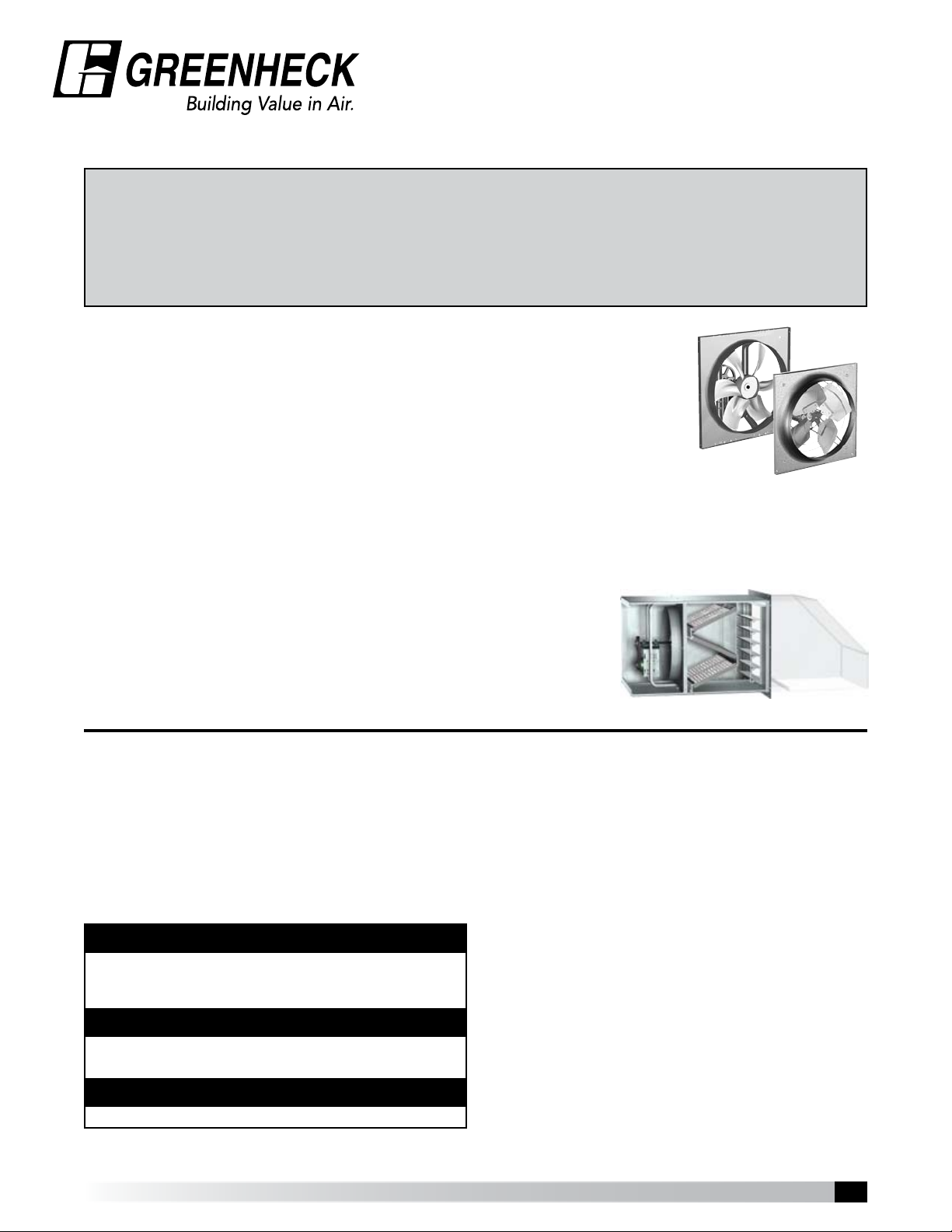
Sidewall Propeller Fans
Belt Drive, Direct Drive and Reversible
Exhaust, Supply and Filtered Supply
Installation, Operation and Maintenance Manual
Please read and save these instructions for future reference. Read carefully before attempting
to assemble, install, operate, or maintain the product described. Protect yourself and others by
observing all safety information. Failure to comply with instructions could result in personal injury
and/or property damage!
Sidewall Propeller Fans
Greenheck’s sidewall propeller fan line is the ideal choice for factory and
warehouse applications where high volumes of air and low pressures are
required. From general ventilation to industrial duty, the range of construction
and performance capabilities offered represent the most comprehensive sidewall
propeller fan line in the industry.
Performance spans the range between 300 to 87,000 cfm (510 to 147,814 m3/hr)
with static pressures to 1.25 in. wg (249 Pa). Fan sizes range from 8 to 54 inches
(203 to 1372 mm) for direct drive and 20 to 72 inches (508 to 1829 mm) for belt
drive. Regardless of fan size, performance or duty level, all Greenheck sidewall
propeller fans are built to perform with the same high standards of reliability and
durability. All models are available in exhaust or supply arrangements.
Models SE1, SS1, SE2, SS2, SCE3, SCS3, SCR3, SBE-1, SBS-1, SBE-2, SBS-2, SBE-3, SBS-3, SBCE, SBCS, and SBCR.
Filtered Supply
Filtered supply wall housings are available in seven sizes for fans ranging
from size 24 to 54 inches (610 to 1372 mm). They are designed with
the draw-thru concept to achieve the highest filter and fan efficiencies.
Permanent 2 inch (51 mm) washable filters are accessed through a bolted
panel and can be easily removed for cleaning.
General Safety Information
Only qualified personnel should install this fan.
Personnel should have a clear understanding of
these instructions and should be aware of general
safety precautions. Improper installation can result
in electric shock, possible injury due to coming in
contact with moving parts, as well as other potential
hazards. Other considerations may be required
if high winds or seismic activity are present. If
more information is needed, contact a licensed
professional engineer before moving forward.
DANGER
Always disconnect, lock and tag power source before
installing or servicing. Failure to disconnect power source
can result in fire, shock or serious injury.
CAUTION
When servicing the fan, motor may be hot enough to
cause pain or injury. Allow motor to cool before servicing.
CAUTION
Precaution should be taken in explosive atmospheres.
1. Follow all local electrical and safety codes, as
well as the National Electrical Code (NEC) and
the National Fire Protection Agency (NFPA),
where applicable. Follow the Canadian Electric
Code (CEC) in Canada.
2. The rotation of the propeller is critical. It must
be free to rotate without striking or rubbing any
stationary objects.
3. Motor must be securely and adequately
grounded.
4. Do not spin fan propeller faster than max
cataloged fan RPM. Adjustments to fan speed
significantly effects motor load. If the fan RPM is
changed, the motor current should be checked
to make sure it is not exceeding the motor
nameplate amps.
5. Do not allow the power cable to kink or come
in contact with oil, grease, hot surfaces,
or chemicals. Replace cord immediately if
damaged.
6. Verify that the power source is compatible with
the equipment.
7. Never open access doors to a duct while the fan
is running.
Sidewall Propeller Fans • Exhaust, Supply and Filtered Supply
1
Page 2

®
Receiving
Upon receiving the product, check to make sure
all items are accounted for by referencing the bill
of lading to ensure all items were received. Inspect
each crate for shipping damage before accepting
delivery. Notify the carrier if any damage is noticed.
The carrier will make notification on the delivery
receipt acknowledging any damage to the product.
All damage should be noted on all the copies of the
bill of lading which is countersigned by the delivering
carrier. A Carrier Inspection Report should be filled
out by the carrier upon arrival and reported to the
Traffic Department. If damaged upon arrival, file
a claim with carrier. Any physical damage to the
unit after acceptance is not the responsibility of
Greenheck Fan Corporation.
Unpacking
Verify that all required parts and the correct quantity
of each item have been received. If any items are
missing, report shortages to your local representative
to arrange for obtaining missing parts. Sometimes it
is not possible that all items for the unit be shipped
together due to availability of transportation and
truck space. Confirmation of shipment(s) must be
limited to only items on the bill of lading.
Note: The filtered supply unit ships with all ordered
components completely factory assembled. The
optional weatherhood ships knocked down for field
assembly and installation.
Storage
Fans are protected against damage during shipment.
If the unit cannot be installed and operated
immediately, precautions need to be taken to prevent
deterioration of the unit during storage. The user
assumes responsibility of the fan and accessories
while in storage. The manufacturer will not be
responsible for damage during storage. These
suggestions are provided solely as a convenience to
the user.
INDOOR
The ideal environment for the storage of fans and
accessories is indoors, above grade, in a low
humidity atmosphere which is sealed to prevent the
entry of blowing dust, rain or snow. Temperatures
should be evenly maintained between 30° to 110°F
(-1° to 43°C), wide temperature swings may cause
condensation and “sweating” of metal parts. All
accessories must be stored indoors in a clean, dry
atmosphere.
Remove any accumulations of dirt, water, ice, or
snow and wipe dry before moving to indoor storage.
To avoid “sweating” of metal parts allow cold parts to
reach room temperature. To dry parts and packages
use a portable electric heater to remove any moisture
build up. Leave coverings loose to permit air
circulation and to allow for periodic inspection.
The unit should be stored at least 3½ inches
(89 mm)
off the floor on wooden blocks covered with moisture
proof paper or polyethylene sheathing. Aisles
between parts and along all walls should be provided
to permit air circulation and space for inspection.
OUTDOOR
Fans designed for outdoor applications may be
stored outdoors, if absolutely necessary. Roads or
aisles for portable cranes and hauling equipment are
needed.
The fan should be placed on a level surface to
prevent water from leaking into the fan. The fan
should be elevated on an adequate number of
wooden blocks so it is above water and snow levels
and has enough blocking to prevent it from settling
into soft ground. Locate parts far enough apart to
permit air circulation, sunlight and space for periodic
inspection. To minimize water accumulation, place all
fan parts on blocking supports so rain water will run
off.
Do not cover parts with plastic film or tarps as these
cause condensation of moisture from the air passing
through heating and cooling cycles. Fan wheels
should be blocked to prevent spinning caused by
strong winds.
Inspection and Maintenance During
Storage
While in storage, inspect fans once per month. Keep
a record of inspection and maintenance performed.
If moisture or dirt accumulations are found on parts,
the source should be located and eliminated. At each
inspection, rotate the wheel by hand ten to fifteen
revolutions to distribute lubricant on motor. If paint
deterioration begins, consideration should be given
to touch-up or repainting. Fans with special coatings
may require special techniques for touch-up or
repair.
Machined parts coated with rust preventive should
be restored to good condition promptly if signs of
rust occur. Immediately remove the original rust
preventive coating with petroleum solvent and clean
with lint-free cloths. Polish any remaining rust from
surface with crocus cloth or fine emery paper and
oil. Do not destroy the continuity of the surfaces.
Thoroughly wipe clean with Tectyl
®
506 (Ashland Inc.)
or the equivalent. For hard to reach internal surfaces
or for occasional use, consider using Tectyl® 511M
Rust Preventive, WD-40® or the equivalent.
Removing From Storage
As fans are removed from storage to be installed
in their final location, they should be protected
and maintained in a similar fashion until the fan
equipment goes into operation.
Sidewall Propeller Fans • Exhaust, Supply and Filtered Supply
2
Page 3
M
W.O.
W.O.
W.O.
M
W.O.
W.O.
M
W.O.
Filters
Wall
Housing
Filter
Section
INTERIOR
Wall
EXTERIOR
Optional 90º
Weatherhood
Filters
Airflow
Optional
Damper
Wall
A
C
B
24 in. 15 in.
Pre-Installation Checks
• Check chart below for correct wall opening
dimensions.
• Check motor voltage and amperage rating for
compatibility with electrical supply. Supply wiring
must be properly fused and conform to local and
national codes.
• Motor load amperage must be checked and
compared to nameplate rating to avoid serious
damage to motor when speed is increased.
Wall Opening Requirements
Wall opening size and propeller-to-damper distance
are two important dimensions for fan installation.
Fans mounted to the wall require a different wall
opening (W.O.) size than those mounted in collars or
wall housings. Propeller-to-damper distance (M) is
important to reduce turbulence and damper flutter
which may lead to premature damper failure.
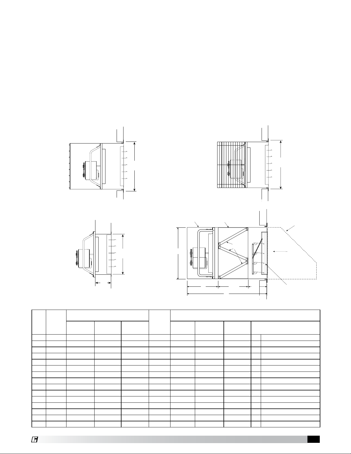
Figure 1 and 2 show the wall opening (W.O.) required
for installations with either a wall housing or collar.
Figure 3 shows the recommended wall opening
(W.O.) and the minimum distance (M) suggested
between the fan and damper for direct to wall
installations.
Figure 4 shows the dimensions and wall opening
(W.O.) required for installations with a filtered supply
wall housing.
Figure 1 - Wall Housing Installation Figure 2 - Wall Collar Installation
Figure 3 - Direct to Wall Installation Figure 4 - Filtered Supply Wall Housing Installation
Recommended Wall Opening (W.O.)
Size
Figures 1
and 2
Square
Figure 3 Figure 4 A B C Filter Quantity & Size
M
Minimum
Fan
Size
Damper
Square
8 10 (254) 14¼ (362) 10½ (267) - 6 (152) - - - -
10 12 (305) 16¼ (413) 12½ (318) - 6 (152) - - - -
12 14 (356) 19¼ (489) 14½ (368) - 7 (178) - - - -
14 16 (406) 21¼ (540) 16½ (419) - 8 (203) - - - -
16 18 (457) 23¼ (591) 18½ (470) - 9 (229) - - - -
18 20 (508) 25¼ (641) 20½ (521) - 10 (254) - - - -
20 22 (559) 27¼ (692) 22½ (572) - 12 (305) - - - -
24 26 (660) 33¾ (857) 26½ (673) 33
30 32 (813) 39¾ (1010) 32½ (826) 39
36 38 (965) 45¾ (1162) 38½ (978) 45
42 44 (1118) 51¾ (1314) 44½ (1130) 513⁄4 (1314) 15 (381) 501⁄8 (1273) 727⁄8 (1851) 34 (864) 6 241⁄8 x 251⁄8 (613 x 638)
48 50 (1270) 57¾ (1467) 50½ (1283) 57
54 56 (1422) 63¾ (1619) 56½ (1435) 633⁄4 (1619) 17 (432) 623⁄8 (1584) 7911⁄16 (2024) 4011⁄16 (1033) 12 231⁄4 x 203⁄4 (591 x 527)
60 62 (1575) 69¾ (1772) 62½ (1588) - 19 (483) - - - -
72 74 (1880) 84¾ (2153) 74½ (1892) - 19 (483) - - - -
All dimensions given in inches (millimeters). Filters are 2 inch (51 mm) nominal thickness. Above filter sizes are actual dimensions.
3
⁄4 (857) 13 (330) 321⁄4 (819) 63 (1600) 24 (610) 4 231⁄4 x 161⁄4 (591 x 413)
3
⁄4 (1010) 13 (330) 381⁄4 (972) 65 (1651) 26 (660) 4 245⁄8 x 191⁄4 (625 x 489)
3
⁄4 (1162) 14 (356) 441⁄4 (1124) 671⁄4 (1708) 28¼ (718) 6 231⁄4 x 221⁄8 (591 x 562)
3
⁄4 (1467) 16 (406) 561⁄8 (1426) 727⁄8 (1851) 34 (864) 12 231⁄4 x 183⁄4 (591 x 476)
Sidewall Propeller Fans • Exhaust, Supply and Filtered Supply®3
Filtered Supply Wall Housing Only
Page 4
®
Optional 90º
Weatherhood
WallWall
INTERIOR EXTERIOR
Wall
Airflow
Mounting
Angles
Temporary
Brace
Wall
500 lb. load
per support
750 lb. load
per support
45º
45º
WallWall
Optional 90º
Weatherhood
WallWall
500 lb. load
per support
500 lb. load
per support
750 lb. load
per support
750 lb. load
per support
45º
45º
WallWall
Optional 90º
Weatherhood
WallWall
WARNING
Always disconnect, lock and tag power source before
installing or servicing. Failure to disconnect power
source can result in fire, shock or serious injury.
Typical Installation
Move fan to the desired location and determine the
method by which the fan is to be mounted as shown
in Figures 1-4 shown on page 3. Optional wall mount
housings (Figure 1) and wall mount collars (Figure
2) provide a convenient means of mounting sidewall
propeller fans while maintaining the proper distance
between propeller and damper.
Attach the fan by inserting a suitable fastener
through each of the prepunched mounting holes in
the fan panel. Care should be taken not to bend or
distort the fan panel or drive components during
installation.
Choose method of support. Attach support to end
of unit (above or below housing) with rods, cable,
angle, etc. (supplied by others) as shown.
Vertical braces must carry a minimum load of 500
pounds per support, and angled (45 °) braces a
minimum of 750 pounds per support based on two
supports.
Step 3 Install Weatherhood
Support Braces
Wall Housing sizes 42 and larger with heavy motors
and all Filtered Supply Wall Housings need additional
bracing.
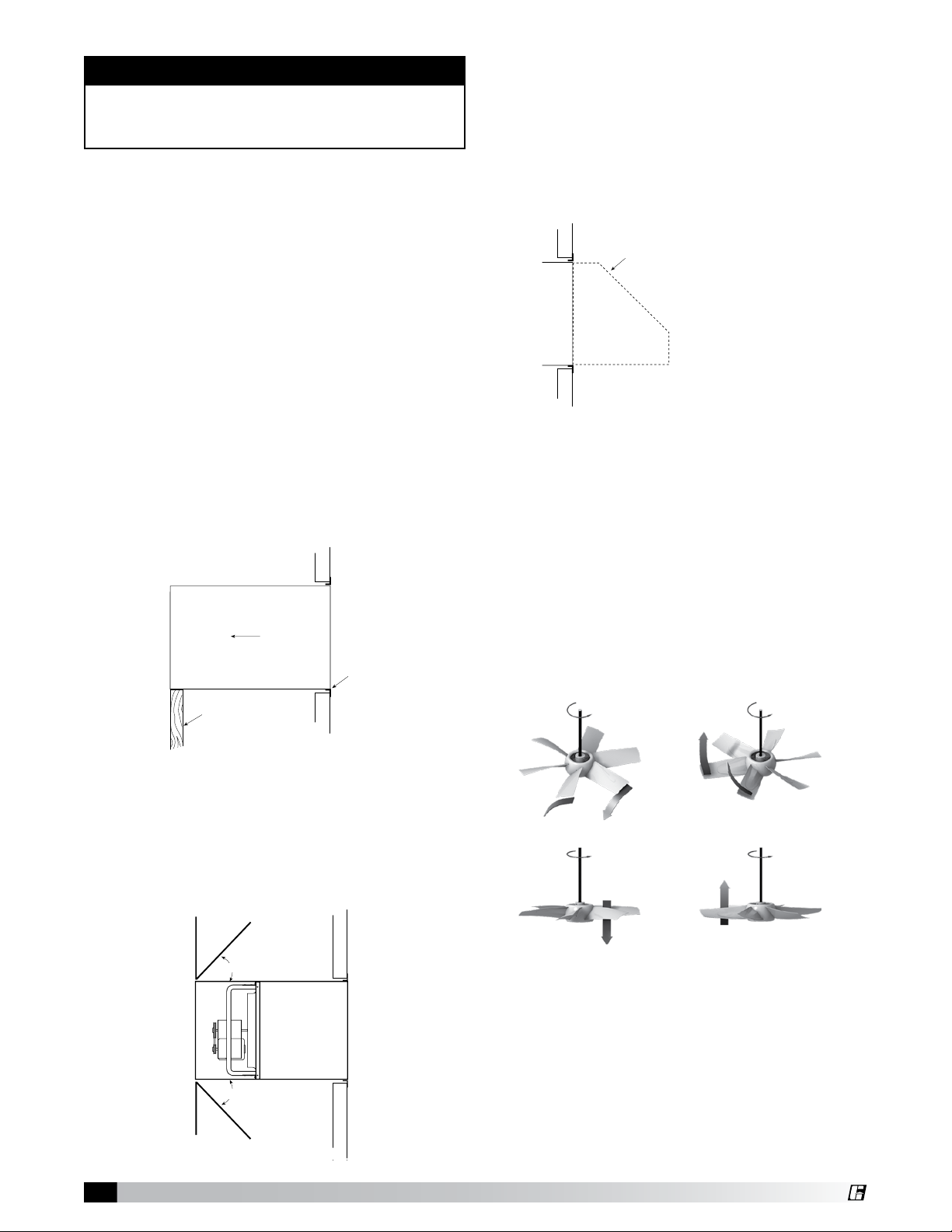
Filtered Supply Wall Housing Installation
Step 1 Install Housing
Install housing through wall opening from outside.
Temporarily brace end of unit until permanent
support braces are installed.
Secure through prepunched holes in angles with
suitable fasteners.
Step 2 Install Support Braces
Position weatherhood over end of wall housing
and fasten through mounting holes with selftapping screws. Caulk, flash and complete
electrical hook-up to finish installation.
Pre-Starting Checks
Check all fasteners and setscrews for tightness. This
is especially important for bearing setscrews.
The propeller should rotate freely and not rub on the
fan panel venturi. Rotation direction of the propeller
should be checked by momentarily turning the unit
on. Propeller blade should cup and throw the air
when rotating in the correct rotation as shown in
the figure below. Rotation should be in the same
direction as the rotation decal affixed to the unit.
Sidewall Propeller Fans • Exhaust, Supply and Filtered Supply
4
For 3-phase installations, fan rotation can be
reversed by simply interchanging any two of the
three electrical leads. For single-phase installations
follow the wiring diagram located on the motor.
For Belt Drive Fans: The adjustable motor pulley is
preset at the factory for the specified fan RPM. Fan
speed can be increased by closing or decreased by
opening the adjustable pulley. Two or three groove
variable pitch pulleys must be adjusted an equal
Page 5
Slack
Side
number of turns open. Any increase in fan speed
represents a substantial increase in horsepower
required from the motor. Always check motor load
amperage and compare to nameplate rating when
changing fan speed.
Routine Maintenance
Once the fan has been put into operation, a periodic
maintenance program should be set up to preserve
the reliability and performance of the fan. Items to
be included in this program are: Belts, Bearings,
Fasteners and Setscrews, Lubrication, and Removal
of Dust and Dirt.
WARNING
Always disconnect, lock and tag power source before
installing or servicing. Failure to disconnect power
source can result in fire, shock or serious injury.
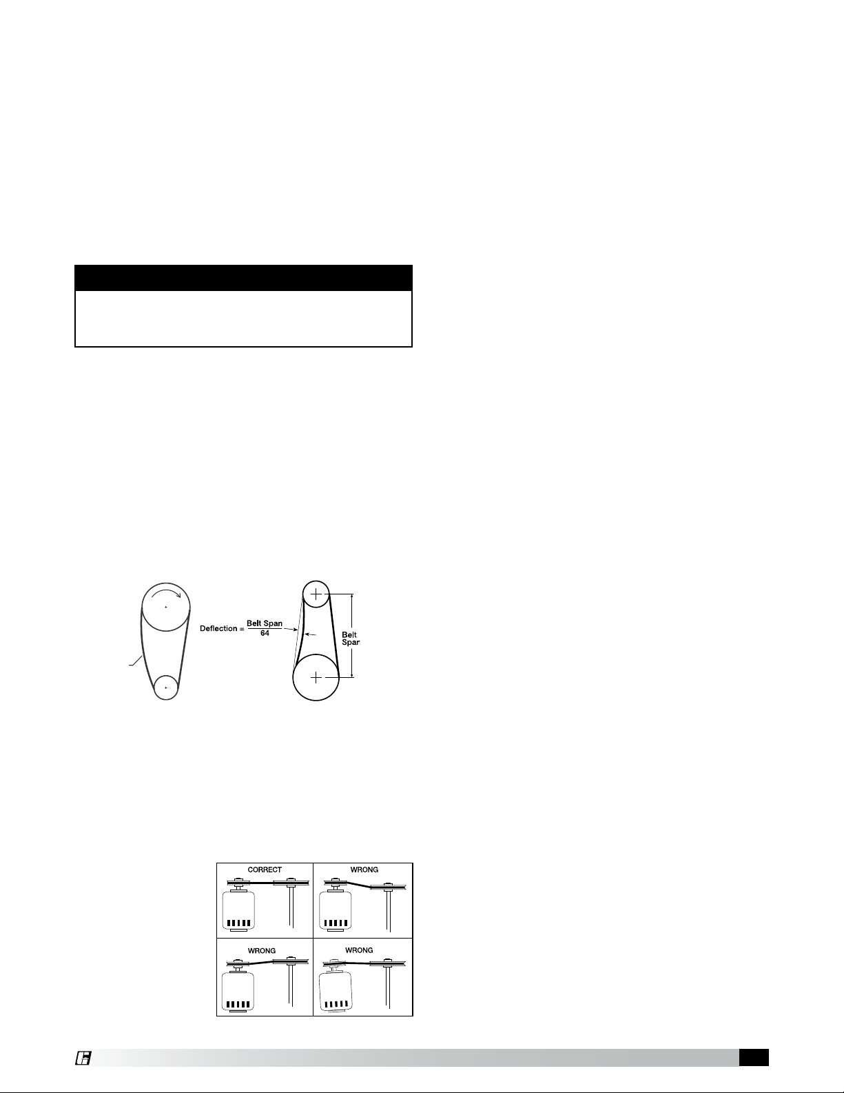
Belts
Premature belt failures are frequently caused by
improper belt tension (either too tight or too loose) or
misaligned pulleys. The proper tension for operating
a V-belt is the lowest tension at which the belts will
not slip at peak load conditions. For initial tensioning,
the proper belt deflection halfway between pulley
centers is 1/64 inch (0.4 mm) for each inch of belt
span. For example, if the belt span is 64 inches
(1626 mm), the belt deflection should be one inch
(25 mm) using moderate thumb pressure at midpoint
of the drive. See figure shown below.
Check belt tension two times during the first 24
hours of operation and periodically thereafter. To
adjust belt tension, simply loosen four fasteners
(two on each side of the motor plate) and slide the
motor plate away from the fan shaft until proper
belt tension is attained. On some fans, fasteners
attaching the motor to the motor plate must be
loosened in order to adjust the belt.
It is very important
that the drive pulleys
remain in proper
alignment after
adjustments are
made. Misalignment
of pulleys will result
in premature belt
wear noise, vibration
and power loss.
Bearings (For belt drive fans only)
Bearings are the most critical moving part of the
fan and should be inspected at periodic intervals.
Locking collars and setscrews, in addition to
fasteners attaching the bearings to the bearing
plate, must be checked for tightness. In a clean
environment and temperatures above 32ºF (0ºC)
and below 200ºF (93ºC), fan shaft bearings with
grease fittings should be lubricated semi-annually
using a high-quality lithium based grease. If unusual
environmental conditions exist, temperatures below
32ºF (0ºC) and above 200ºF (93ºC), moisture or
contaminants, more frequent lubrication is required.
With the unit running, add grease very slowly with
a manual grease gun until a slight bead of grease
forms at the seal. Be careful not to unseat the seal
by over lubricating or using excessive pressure.
Bearings without grease fittings are lubricated for
life.
Fasteners and Setscrews
Any fan vibration has a tendency to loosen
mechanical fasteners. A periodic inspection should
include checking all fasteners and setscrews for
tightness. Particular attention should be paid to
setscrews or taper-lock bushings attaching the
propeller to the motor shaft and the motor shaft to
the bearings. Loose bearing setscrews will lead to
premature failure of the fan shaft. In addition, check
all fasteners attaching the motor to the motor plate.
Lubrication
Refer to the paragraph on bearings for bearing
lubrication. Many fractional horsepower motors
installed on the smaller fans are lubricated for life
and require no further attention. Motors equipped
with oil holes should be oiled in accordance with the
manufacturer’s instructions printed on the motor.
Use a high grade SAE 20 machine oil and use caution
not to over lubricate. Motors supplied with grease
fittings should be greased according to directions
printed on the motor.
Removal of Dust and Dirt
Dirt clogs cooling openings on the motor housing,
contaminates bearing lubricant and collects on
propeller blades causing severe imbalance if left
unchecked. The exterior surface of the motor, fan
panel and entire propeller should be thoroughly
cleaned periodically. Use caution and do not allow
water or solvents to enter the motor or bearings.
Motors or bearings must not be sprayed with steam
or water.
The filters also require periodic cleaning. The 2 inch
(51 mm) washable aluminum filters are accessed
through the bolted access panel.
Sidewall Propeller Fans • Exhaust, Supply and Filtered Supply®5
Page 6

®
Troubleshooting
WARNING: Before taking any corrective action, make certain unit is not capable of operation during repairs.
PROBLEM CAUSE CORRECTIVE ACTION
Too Much Airflow
Reduced Airflow
Excessive Noise
Fan Does Not
Operate
Resistance lower than designed Decrease fan speed.
Check backdraft dampers for proper operation. Remove
System resistance too high
Fan too close to damper Increase distance between fan and damper.
Fan speed too low Increase fan speed.
Excessive dirt buildup on
propeller
Bearings
V-Belt drive
Excessive vibration
Defective motor Replace motor.
Variable Frequency Drive (VFD)
Debris Remove all debris from the fan.
Electrical Supply
Drive Check for broken or worn belts. Tighten loose pulleys.
Motor
obstructions in ductwork. Clean dirty filters. Check for adequate
supply air for exhaust fans or exhaust air for supply fans.
Clean propeller.
Tighten collars and fasteners. Lubricate bearings. Replace
defective bearings.
Tighten pulleys on motor and fan shaft. Adjust belt tension. Align
pulleys properly. Replace worn belts or pulleys. See Maintenance.
Clean dirt buildup from propeller. Check all setscrews and
fasteners for tightness. Check for worn bearing. Correct propeller
imbalance. Check for loose dampers, guards or ductwork.
Check VFD for drive setting, some controllers are able to be adjust
to lower the harmonic noises sometimes heard during operation by
adjusting a simple setting on the controller.
Check fuses/circuit breakers. Check for switches turned off or
disconnected. Check for correct supply voltage.
Assure motor is correct horsepower and not tripping overload
protector.
Maintenance Documentation
Job Information
Job Name:___________________________________ Service Organization: _________________________________
Address: ____________________________________ Address: _____________________________________________
City: ________________________________________ City: _________________________________________________
State: _______________ Zip: __________________ State: _______________ Zip: __________________________
Phone: ______________________________________ Phone: ______________________________________________
Contact Person: ______________________________ Work Done By: _______________________________________
Nameplate Information Field Start-Up Documentation
Model: ______________________________________
Volts: ________ Hertz: ________ Phase: ______ Actual Voltage: _______ Hertz: ______ Phase: _________
Amps: _______________ Mark: ________________ Actual Amperage: ____________________________________
Supply hp: ___________ Exhaust hp: __________ Blower Rotation: _____________________________________
Serial Number: _______________________________ Air Volume: Design cfm: _____________________________
Model Voltage: _______________________________ Actual cfm: ______________________________
Motor Amperage: ____________________________ Level of fan (L or H): __________________________________
Fan RPM: ___________________________________ Fan RPM Range (min.) ___________ (max.) _____________
Sidewall Propeller Fans • Exhaust, Supply and Filtered Supply
6
Page 7

1
2
3
4
5
6
7
8
9
10
Exhaust
Airflow
Airflow
Supply
1
1
2
2
3
3
4
4
5
5
6
6
7
7
8
8
9
9
10
10
11
Exhaust
Airflow
Exhaust
Airflow
Airflow
Supply
Airflow
Supply
Parts List
NOTE
Each fan bears a manufacturer’s nameplate with model number and serial number embossed. This information will
assist the local Greenheck representative and the factory in providing service and replacement parts. Before taking any
corrective action, make certain unit is not capable of operation during repairs.
CAUTION
A fan manufactured with an explosion resistant motor does not certify the entire unit to be explosion proof.
Parts List - Belt Drive
SBE-1, SBS-1, SBE-2 and SBS-2 (L and H propellers)
1. Fan Panel
2. Propeller
3. Drive Frame Channel (2)
4. Motor /Bearing Plate
5. Motor
6. Motor Pulley
7. Shaft Pulley
8. Fan Shaft
9. Bearings (2)
10. Belt
SBE-3, SBS-3, SBCE, SBCS, and SBCR (L and H propellers)
1. Fan Panel
2. Propeller
3. Drive Frame Channel (2)
4. Motor Plate
5. Motor
6. Motor Pulley
7. Shaft Pulley
8. Fan Shaft
9. Bearings (2)
10. Belt
11. Bearing Plate
Sidewall Propeller Fans • Exhaust, Supply and Filtered Supply®7
Page 8

®
1
1
2
2
3
3
4
4
5
5
6
Exhaust
Airflow
Exhaust
Airflow
Airflow
Supply
Airflow
Supply
1
2
3
4
5
6
Exhaust
Airflow
Airflow
Supply
Parts List - Direct Drive
SE1 and SS1 (Sizes 8 thru 12 - D, G and E motor speeds)
SE1 and SS1 (Sizes 12 thru 24 - A, B and C motor speeds)
SE2 and SS2
SCE3, SCS3 and SCR3
1. Fan Panel
2. Propeller
3. Drive Frame/Motor Support
4. Motor
5. Riser Blocks (4) - supply fan only
6. Shaft Extension- supply fan only
1. Fan Panel
2. Propeller
3. Drive Frame Channels (2)
4. Motor Plate
5. Motor
Warranty
Greenheck warrants this equipment to be free from defects in material and workmanship for a period of one year
from the purchase date. Any units or parts which prove defective during the warranty period will be replaced at
our option when returned to our factory, transportation prepaid. Motors are warranted by the motor manufacturer
for a period of one year. Should motors furnished by Greenheck prove defective during this period, they should
be returned to the nearest authorized motor service station. Greenheck will not be responsible for any removal or
installation costs.
As a result of our commitment to continuous improvement, Greenheck reserves the right to change specifications
without notice.
Greenheck Catalog Sidewall Propeller Fans provides additional
information describing the equipment, fan performance,
available accessories, and specification data.
AMCA Publication 410-96, Safety Practices for
Users and Installers of Industrial and Commercial
Fans, provides additional safety information. This
publication can be obtained from AMCA International,
Inc. at: www.amca.org.
Phone: (715) 359-6171 • Fax: (715) 355-2399 • E-mail: gfcinfo@greenheck.com • Website: www.greenheck.com
8
471755 • Sidewall Propeller Fans IOM • Rev. 2, October 2008 Copyright 2008 © Greenheck Fan Corp
 Loading...