

Greenheck Fan OFSD-312 User Manual

Model OFSD-312
R
Application
Out of Wall Combination Fire Smoke Dampers
Model OFSD-312 is an ‘out of the wall’ high performance combination
fire smoke damper with class II leakage. OFSD-312 is approved for
use in walls, partitions, and floors with fire resistance ratings less than
3 hours. Removal of wall grille allows access to actuator and other
components. High strength airfoil blades insure the lowest resistance
to airflow in HVAC systems with velocities to 3000 fpm (15.2 m/s)
and pressures to 4 in. wg (1 kPa). Model OFSD-312 shall be installed
vertically (with blades running horizontal) or horizontally and is rated
for airflow and leakage in either direction.
Ratings
UL555 Fire Resistance Rating:
Fire Rating: 1
Dynamic Closure Rating: Actual ratings are size dependent
Max. Velocity: up to 3000 fpm (15.2 m/s)
Max. Pressure: 4 in. wg (1 kPa) - differential pressure
UL555S Leakage Rating:
Leakage Class: I
Operational Rating: Actual ratings are size dependent
Max. Velocity: up to 3000 fpm (15.2m/s)
Max. Pressure: 4 in. wg (1 kPa)
Max. Temperature: 350ºF (177ºC)- depending upon the
actuator
1
⁄2 hours in walls
Standard Construction
Frame: 5 in. x 1 in. (127mm x 25mm)
galvanized steel hat channel with
reinforced corners. A low profile
head and sill are used on sizes less
than 17 in. (432mm) high.
Blades: Double skin airfoil shape of
galvanized steel with full length
structural reinforcement. 14 ga.
(2mm) equivalent thickness.
Seals: Extruded silicone rubber blade seals.
Flexible stainless steel jamb seals.
Linkage: Concealed in jamb
Fusible Link: RRL 165°F (74ºC)
Axles:
Bearings: Bronze sleeve type
Sleeve: Galvanized; wrapped with thermal
blanket
1
⁄2 in. (13mm) dia. plated steel
Steel Airfoil Blades
UL 555S Leakage Class I
UL555 11⁄2 Hour Fire Resistance Rating
Horizontal or Vertical Mount
Model OFSD-312 meets the requirements for fire
dampers, smoke dampers and combination fire
smoke dampers established by:
National Fire Protection Association
NFPA Standards 80, 90A, 92A, 92B, 101 & 105
IBC International Building Codes
ICBO Uniform Building Codes
CSFM California State Fire Marshal
Fire Damper Listing (#3225-0981:103)
Leakage (Smoke) Damper Listing (#3230-0981:104)
New York City (MEA listing #260-91-M)
“UL CLASSIFIED (see complete marking on
product)”
“UL CLASSIFIED to Canadian safety standards
(see complete marking on product)”
Standard 555 & 555S (Listing #R13317)
Greenheck Fan Corporation certifies that the
model OFSD-312 shown herein is licensed to
bear the AMCA Seal. The ratings shown are
based on tests and procedures performed in
accordance with AMCA Publication 511 and
comply with the requirements of the AMCA
Certified Ratings Programs. The AMCA Certified
Ratings Seal applies to air performance ratings
only.
Size Limitations:
Minimum Size: 12 in.W x 12 in. H
(305mm x 305mm)
Maximum Size:
Single section: 32 in. W x 30 in. H
(813mm W x 762mm H)
Multiple Section: 36 in.W x 36 in. H
(914mm x 914mm)
Optional Features:
• POCretainingAngles
• RRL/OCI(openclosedindicationswitches)
• 165ºF(74ºC),212ºF(100ºC),250ºF(121ºC),350ºF(177ºC)RRL’s
available
•TOR(remoteoverrideallowsdampertoperformsmoke
management functions during fire emergency.)
• Electricorpneumaticactuatorstoaccomplishsmoke
management and system functions.
•Smokedetectors
•Momentaryswitch
•PRV(pneumaticreliefvalve)
•Securitybars
•Sealedtransitionandsleeves
Installation instructions available at www.greenheck.com
* W & H dimensions furnished approximately 1⁄4 in. (6mm) undersize.
Add blanket thickness (
overall sleeved damper dimension)
Oversize wall opening as follows:
Nominal damper size plus 3⁄8 in.(9.5mm) (see Page 6)
1
⁄8 in.[3mm]) and sleeve thickness for
Pressure Drop Data OFSD-312
5D 6D
5D 6D
5D
D
4 (W) (H)
3.14
5D 6D
5D
D
4 (W) (H
)
3.14
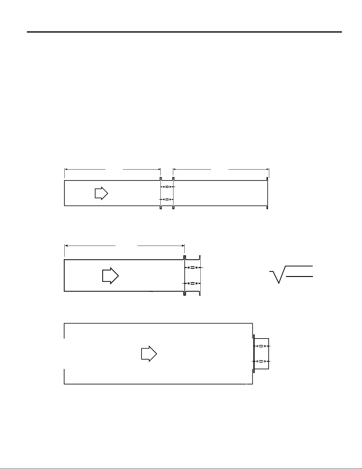
This pressure drop testing was conducted in accordance with AMCA Standard 500-D using the three configurations shown. All
data has been corrected to represent standard air at a density of .075 lb/ft3 (1.201 kg/m3).
Actual pressure drop found in any HVAC system is a combination of many factors. This pressure drop information along with an
analysis of other system influences should be used to estimate actual pressure losses for a damper installed in a given HVAC
system.
AMCA Test Figures
Figure 5.3 Illustrates a fully ducted damper. This configuration has the lowest pressure drop of the three test configurations
because entrance and exit losses are minimized by straight duct runs upstream and downstream of the damper.
Figure 5.2 Illustrates a ducted damper exhausting air into an open area. This configuration has a lower pressure drop than
Figure 5.5 because entrance losses are minimized by a straight duct run upstream of the damper.
Figure 5.5 Illustrates a plenum mounted damper. This configuration has the highest pressure drop because of extremely high
entrance and exit losses due to the sudden changes of area in the system.
Figure 5.3
Figure 5.2
Figure 5.5
 Loading...