

Page 1

Out Of Wall Combination FIRE SMOKE DAMPERS
R
APPLICATION
Model OFSD-211 is approved for use in walls, partitions, and floors
with fire resistance ratings less than 3 hours. OFSD-211 is an ‘out of
the wall’ high performance combination fire smoke damper with 3V
style blades. Removal of wall grille allows access to actuator and
other components. This model's operational ratings of 2000 fpm (10.2
m/s) and pressures to 4 in. wg (1 kPa). Model OFSD-211 shall be
installed vertically (with blades running horizontal) or horizontally and
is rated for airflow and leakage in either direction.
Ratings
UL555 Fire Resistance Rating:
Fire Rating: 1
Dynamic Closure Rating: Actual ratings are size dependent
Max. Velocity: 2000 fpm (10.2 m/s)
Max. Pressure: 4 in. wg (1 kPa) - differential
pressure
UL555S Leakage Rating:
Leakage Class: I
Operational Rating: Actual ratings are size dependent
Max. Velocity: 2000 fpm (10.2m/s)
Max. Pressure: 4 in. wg (1 kPa)
Max. Temperature: 350ºF (177ºC)- depending upon the
actuator
STANDARD CONSTRUCTION
1
⁄2 hours in walls
Model OFSD-211
Steel 3V Blades
UL 555S Leakage Class I
UL555 11⁄2 Hour Fire Resistance Rating
Horizontal or Vertical Mount
Model OFSD-211 meets the requirements for fire
dampers, smoke dampers and combination fire
smoke dampers established by:
National Fire Protection Association
NFPA Standards 80, 90A, 92A, 92B, 101 & 105
IBC International Building Codes
ICBO Uniform Building Codes
CSFM California State Fire Marshal
Fire Damper Listing (#3225-0981:103)
Leakage (Smoke) Damper Listing (#3230-0981:104)
New York City (MEA listing #260-91-M)
“UL CLASSIFIED (see complete marking on
product)”
“UL CLASSIFIED to Canadian safety standards
(see complete marking on product)”
Standard 555 & 555S (Listing #R13317)
Frame: 5 in. x 1 in. (127mm x 25mm)
galvanized steel hat channel with
reinforced corners. A low profile
head and sill are used on sizes less
than 17 in. (432mm) high.
Blades: 16 ga. (1.5mm) galvanized steel,
reinforced with 3 longitudinal
structurally designed vee's.
Seals: Extruded silicone rubber blade seals.
Flexible stainless steel jamb seals.
Linkage: Concealed in jamb
Closure Device: UL listed 165°F (74ºC) RRL
Axles: ½ in. (13mm) dia. plated steel
Bearings: Bronze sleeve type
Sleeve: Galvanized; wrapped with thermal
blanket
SIZE LIMITATIONS:
Minimum Size: 12 in. W x 12 in. H
(305mm x 305mm)
Maximum Size: Single section: 36 in. W x 36 in. H
(914mm x 914mm)
OPTIONAL FEATURES:
• POC retaining Angles
• RRL/OCI (open closed indication switches)
• 165ºF (74ºC), 212ºF (100ºC), 250ºF (121ºC), 350ºF (177ºC) RRL’s
available
• TOR (remote override allows damper to perform smoke
management functions during fire emergency.)
• Electric actuators
• Momentary switch
• Security bars
• Sealed transition and sleeves
Installation instructions available at www.greenheck.com
Greenheck Fan Corporation certifies that the
model OFSD-211 shown herein is licensed to bear
the AMCA Seal. The ratings shown are based on
tests and procedures performed in accordance
with AMCA Publication 511 and comply with the
requirements of the AMCA Certified Ratings Programs. The AMCA Certified Ratings Seal applies to
air performance ratings only.
* W & H dimensions furnished approximately 1⁄4 in. (6mm) undersize.
(Add blanket thickness (
sleeved damper dimension)
Oversize wall opening as follows:
Nominal damper size plus
1
⁄8 in.[3mm]) and sleeve thickness for overall
3
⁄8 in.(9.5mm) (see Page 6)
Page 2
Pressure Drop Data OFSD-211
5D 6D
5D 6D
5D
D
4 (W) (H)
3.14
5D 6D
5D
D
4 (W) (H
)
3.14
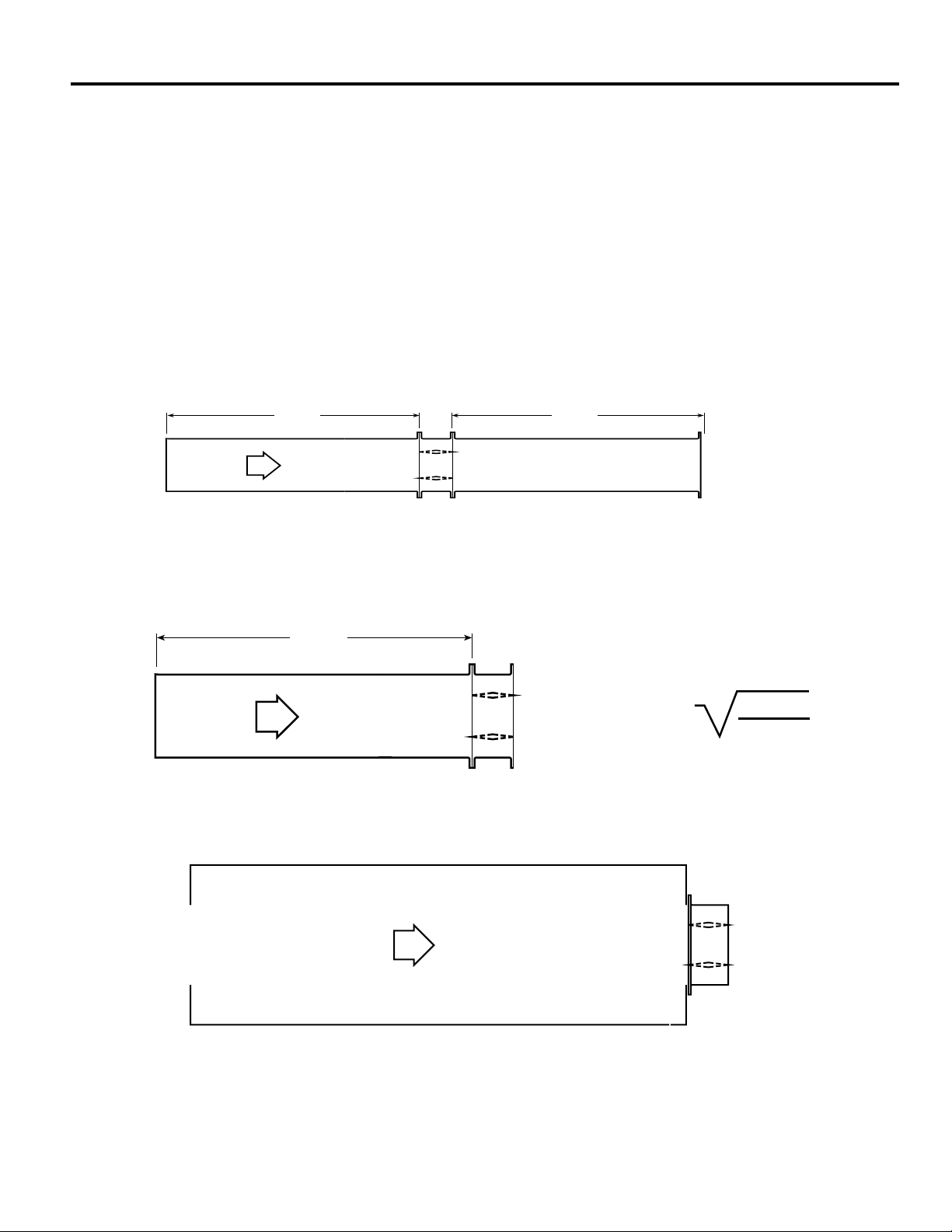
This pressure drop testing was conducted in accordance with AMCA Standard 500-D using the three configurations shown. All
data has been corrected to represent standard air at a density of .075 lb/ft3 (1.201 kg/m3).
Actual pressure drop found in any HVAC system is a combination of many factors. This pressure drop information along with an
analysis of other system influences should be used to estimate actual pressure losses for a damper installed in a given HVAC
system.
AMCA Test Figures
Figure 5.3 Illustrates a fully ducted damper. This configuration has the lowest pressure drop of the three test configurations
because entrance and exit losses are minimized by straight duct runs upstream and downstream of the damper.
Figure 5.2 Illustrates a ducted damper exhausting air into an open area. This configuration has a lower pressure drop than
Figure 5.5 because entrance losses are minimized by a straight duct run upstream of the damper.
Figure 5.5 Illustrates a plenum mounted damper. This configuration has the highest pressure drop because of extremely high
entrance and exit losses due to the sudden changes of area in the system.
Figure 5.3
Figure 5.2
Figure 5.5
Page 3

R
AMCA 5.2 Pressure Drop OFSD-211
5D 6D
5D
D
4 (W) (H)
3.14
Velocity (fpm)
Pressure Drop
(in. wg)
Velocity (fpm)
Pressure Drop
(in. wg)
Velocity (fpm)
Pressure Drop
(in. wg)
Velocity (fpm)
Pressure Drop
(in. wg)
500 0.04 500 0.02 500 0.01 5000.01
1000 0.14 10000.07 10000.04 1000 0.06
15000.31 15000.16 15000.09 1500 0.13
2000 0.55 20000.29 20000.1620000.23
2500 0.86 25000.45 25000.2525000.36
30001.24 30000.65 30000.3630000.52
3500 1.69 3500 0.89 3500 0.49 3500 0.70
4000 2.20 4000 1.16 4000 0.64 4000 0.92
12 in. x 12 in. (305mm x 305mm)
24 in. x 24 in. (610mm x 610mm)
36 in. x 36 in. (914mm x 914mm)
12 in. x 48 in. (305mm x 1219mm)
Velocity (fpm)
Pressure Drop
(in. wg)
5000.03
1000 0.10
1500 0.23
2000 0.41
2500 0.63
3000 0.91
3500 1.24
4000 1.62
48 in. x 12 in. (1219mm x 305mm)
* This size is based on multi-section unit.
Greenheck Fan Corporation certifies that the
model OFSD-211 shown herein is licensed to bear
the AMCA Seal. The ratings shown are based on
tests and procedures performed in accordance
with AMCA Publication 511 and comply with the
requirements of the AMCA Certified Ratings Programs. The AMCA Certified Ratings Seal applies to
air performance ratings only.
Page 4

R
AMCA 5.3 Pressure Drop OFSD-211
5D 6D
Velocity (fpm)
Pressure Drop
(in. wg)
Velocity (fpm)
Pressure Drop
(in. wg)
Velocity (fpm)
Pressure Drop
(in. wg)
Velocity (fpm)
Pressure Drop
(in. wg)
500 0.02 500 0.01 5000.01 5000.01
10000.09 10000.04 1000 0.03 1000 0.04
15000.20 1500 0.09 1500 0.06 1500 0.10
20000.36 20000.16 2000 0.11 2000 0.17
25000.56 2500 0.25 2500 0.17 2500 0.27
30000.81 30000.3530000.24 3000 0.39
3500 1.10 3500 0.48 3500 0.33 3500 0.53
40001.44 40000.63 4000 0.42 4000 0.70
12 in. x 12 in. (305mm x 305mm)
24 in. x 24 in. (610mm x 610mm)
36 in. x 36 in. (914mm x 914mm)
12 in. x 48 in. (305mm x 1219mm)
Velocity (fpm)
Pressure Drop
(in. wg)
500 0.02
1000 0.07
1500 0.16
2000 0.29
2500 0.45
3000 0.64
3500 0.88
4000 1.14
48 in. x 12 in. (1219mm x 305mm)
* This size is based on multi-section unit.
Greenheck Fan Corporation certifies that the
model OFSD-211 shown herein is licensed to bear
the AMCA Seal. The ratings shown are based on
tests and procedures performed in accordance
with AMCA Publication 511 and comply with the
requirements of the AMCA Certified Ratings Programs. The AMCA Certified Ratings Seal applies
to air performance ratings only.
Page 5

AMCA 5.5 Pressure Drop OFSD-211
R
5D 6D
5D
D
4 (W) (H)
3.14
Velocity (fpm)
Pressure Drop
(in. wg)
Velocity (fpm)
Pressure Drop
(in. wg)
Velocity (fpm)
Pressure Drop
(in. wg)
Velocity (fpm)
Pressure Drop
(in. wg)
5000.06500 0.03 5000.03 500 0.03
1000 0.22 1000 0.14 1000 0.12 1000 0.13
1500 0.50 1500 0.31 1500 0.26 1500 0.30
2000 0.89 2000 0.54 2000 0.46 2000 0.53
2500 1.39 2500 0.85 2500 0.73 2500 0.83
3000 2.00 3000 1.22 3000 1.05 3000 1.19
3500 2.72 3500 1.66 3500 1.42 3500 1.62
4000 3.55 4000 2.17 4000 1.86 4000 2.11
12 in. x 12 in. (305mm x 305mm)
24 in. x 24 in. (610mm x 610mm)
36 in. x 36 in. (914mm x 914mm)
12 in. x 48 in. (305mm x 1219mm)
Velocity (fpm)
Pressure Drop
(in. wg)
5000.04
1000 0.17
1500 0.38
2000 0.67
2500 1.04
3000 1.50
3500 2.05
4000 2.67
48 in. x 12 in. (1219mm x 305mm)
* This size is based on multi-section unit.
Greenheck Fan Corporation certifies that the
model OFSD-211 shown herein is licensed to bear
the AMCA Seal. The ratings shown are based on
tests and procedures performed in accordance
with AMCA Publication 511 and comply with the
requirements of the AMCA Certified Ratings Programs. The AMCA Certified Ratings Seal applies to
air performance ratings only.
Page 6

X
Grille
(Supplied by
others)
Factory supplied thermal
blanket around sleeve
Fire rated barrier
Combination Fire
Smoke Damper
7 1⁄
2
"
Max.
5 in.
A
Sleeve Length
Application Data OFSD-211
Nominal Damper
Width +
3
8
in.
Nominal
Damper
Height +
3
/8 in.
Wall
Fire Smoke Damper
With Sleeve And
Thermal Blanket
/
Actuator Space Envelopes
The drawing below and corresponding table show the minimum dimensions
required for internal actuator mounting on OFSD-211s. The standard mounting
locations provide enough space for the mounting of actuators and controls plus
allowing space for a grille and duct connection (see Sleeve Length below).
Actuator Space
Envelopes
ML-4XXX series
MS4XXX series
'X' Dimension 5.88 in. (149mm) 5.88 in. (149mm)
Minimum Width 12 in. (305mm) 12 in. (305mm)
Minimum Height 12 in. (305mm) 12 in. (305mm)
Sleeve Information
‘Sleeve Length’ = Depth of Grille (or Register)
+ X (Actuator: see table above)
+ 5 in. [127mm] (Damper Width)
+ 1.25 in. [31.8mm] (for duct connection)
(round up to nearest length: 14 in., 16 in., 18 in.,
‘Sleeve Gauge’ = 16 Ga. or 20 Ga. (1.5mm or 1mm)
or 20 in. [356, 406, 457, or 508mm])
Honeywell
MS4120 series
Wall Opening Sizing
To accommodate for sleeve and thermal blanket thickness,
the wall opening must be oversized by
shown. For example, if the nominal damper size required
is 18 in. x 14 in. (457mm x 356mm), the wall opening size
needs to be 18
damper itself is undersized
for an actual damper size of 17
3
⁄8 in. x 14 3⁄8 in. (467mm x 365mm). The
1
⁄4 in. (6mm) on each dimension
3
349mm). This is also the inside dimensions of the sleeve (for
grille considerations).
3
⁄8 in. (9.5mm) as
⁄4 in. x 13 3⁄4 in. (451mm x
Specifications
Combination Fire Smoke Dampers meeting the following specifications shall be furnished and installed where shown on plans and/or
as described in schedules. Dampers shall meet the requirements of
NFPA 80, 90A, 92A, 92B, 101 & 105 and further shall be tested, rated
and labeled in accordance with the latest edition of UL Standards 555
and 555S. Dampers shall have a UL555 fire rating of 1½ hours and
be of low leakage design qualified to UL 555S Leakage Class I.
Each damper /actuator combination shall have a UL555S elevated
temperature rating of 250°F (121°C) minimum and shall be operational
and dynamic rated to operate at maximum design air flow at its
installed location. Each damper shall be supplied with an appropriate
actuator installed by the damper manufacturer at the time of damper
fabrication. Damper actuator shall be (specifier select one of the
following) electric type for 120 (24 or 230) volt operation.
Damper blades shall be 16 ga. (1.5mm) galvanized steel 3V type with
three longitudinal grooves for reinforcement. Damper frame shall
be galvanized steel formed into a structural hat channel shape with
reinforced corners. Bearings shall be sintered bronze sleeve type
rotating in extruded holes in the damper frame. Blade edge seals
shall be silicone rubber designed to inflate and provide a tighter seal
against leakage as pressure on either side of the damper increases.
Jamb seals shall be stainless steel compression type. Blades shall be
completely symmetrical relative to their axle pivot point, presenting
identical resistance to airflow in either direction or pressure on either
side of the damper. Each damper shall be supplied with a factory
mounted sleeve; sleeve shall be wrapped with UL approved thermal
barrier material.
The Damper Manufacturer's submittal data shall certify all air performance pressure drop data is licensed in accordance with the AMCA
Certified Ratings Program for Test Figures 5.2, 5.3, and 5.5. Damper
air performance data shall be developed in accordance with the latest edition of AMCA Standard 500-D. Dampers shall be labeled with
the AMCA Air Performance Seal.
Damper must be rated for mounting vertically (with blades running
horizontal) or horizontally and be UL 555S rated for leakage and
airflow in either direction through the damper. Each damper shall be
supplied with a 165°F (74°C) RRL.
The basis of design is Greenheck Model OFSD-211.
Copyright ©2006 Greenheck Fan Corporation
OFSD-211 Rev 3 June 2006
 Loading...