

Page 1
Fan Selection
Application-Based Selection
Performance Theory
Page 2
SELECTING THE RIGHT FAN FOR THE JOB
This book is designed to help you select the fan that will best
fit the application for which it is intended. With the large
number of different fan types and sizes available it's
necessary to know which fan model does the best job in
certain applications and then be able to select the most
economical fan size for the job.
With that in mind, this guide is constructed in three sections.
Section One describes how to select a fan using catalog
performance tables with a given air volume and static
pressure. This section also interprets Greenheck model
numbers and illustrates the relationship between fan speed
and airflow.
Section Two covers the basics of fan selection—determining
the proper fan model, air volume, static pressure and
loudness appropriate for a given application. This is
important when your customer does not know the amount of
air to be moved or the resistance to airflow that will be
encountered. This section also illustrates proper fan
installation and proper wheel rotation.
Section Three goes beyond fan selection with information
of a more comprehensive and technical nature about air
movement and air systems.
Page 3
TABLE OF CONTENTS
SECTION 1
INTRODUCTION TO FAN SELECTION
Terms . . . . . . . . . . . . . . . . . . . . . . . . . . . . . . . .4
Model Designation . . . . . . . . . . . . . . . . . . . . . .4
Reading Performance Charts . . . . . . . . . . . . . .5
Matching a Specification . . . . . . . . . . . . . . . . .7
Cross Reference Chart . . . . . . . . . . . . . . . . . . .8
SECTION 2
FAN SELECTION BASED ON FAN APPLICATION
Basic Overview. . . . . . . . . . . . . . . . . . . . . . . . .9
Commercial Kitchen Ventilation . . . . . . . . . . .10
General Commercial Ventilation . . . . . . . . . . .12
High Static Pressure Ventilation . . . . . . . . . .15
Determining CFM . . . . . . . . . . . . . . . . . . . . . .16
Determining Static Pressure . . . . . . . . . . . . .17
Sound Levels . . . . . . . . . . . . . . . . . . . . . . . . .19
Motor Horsepower . . . . . . . . . . . . . . . . . . . . .19
Installation . . . . . . . . . . . . . . . . . . . . . . . . . . .20
Wheel Rotation . . . . . . . . . . . . . . . . . . . . . . . .20
SECTION 3
FAN PERFORMANCE
Fan Dynamics . . . . . . . . . . . . . . . . . . . . . . . . .21
System Dynamics . . . . . . . . . . . . . . . . . . . . . .21
Combining Fan and System Dynamics . . . . . .22
Adjusting Fan Performance . . . . . . . . . . . . . .23
Fan Laws . . . . . . . . . . . . . . . . . . . . . . . . . . . .24
Page 4
INTRODUCTION TO FAN SELECTION
This is the first and most basic of this manual’s three
sections, all of which are designed to enable you to
select the right fan for the job. Look at this first section
as a “user’s manual” for Greenheck literature. It will
answer the following questions (and more): What is a
SONE? How are model numbers and performance
tables used to select a fan? How are direct drive and
Terms
cfm - Cubic Feet Per Minute. A measure of airflow.
Ps - Static Pressure. Resistance to airflow measured in inches of water gauge.
sone - A measure of loudness. One sone can be approximated as the loudness of a quiet
refrigerator at a distance of 5 feet. Sones follow a linear scale, that is, 10 sones are
twice as loud as 5 sones.
Bhp - Brake Horsepower. A measure of power consumption. Used to determine the proper
motor horsepower and wiring.
hp - Horsepower. Used to indicate a fan’s motor size.
rpm - Revolutions Per Minute. Measure of fan speed.
TS - Tip Speed. The speed of the tip of a fan wheel or prop measured in feet per minute.
AMCA - Air Movement and Control Association. A nationally recognized association which
establishes standards for fan testing and performance ratings. AMCA also licenses air
volume and sound certified ratings.
belt driven fans different? What types of motors and
accessories are used with these fans? Are there
Greenheck fans that will match the size and
performance of fans from other manufacturers? The
goal is to understand and use the Greenheck literature
as an important tool in filling a customer’s fan order.
Model Designation
For Greenheck belt drive models, the model
designation tells the model type, size and the motor hp.
EXAMPLE: GB-090-6
Model is GB hp is 1/6
Nominal Wheel Dia. 9 in.
For direct drive units, the model designation tells the
model type, the size and the motor/fan rpm.
EXAMPLE: G-121- B
Model is G rpm is 1140
Nominal Wheel Dia. 12 in.
4
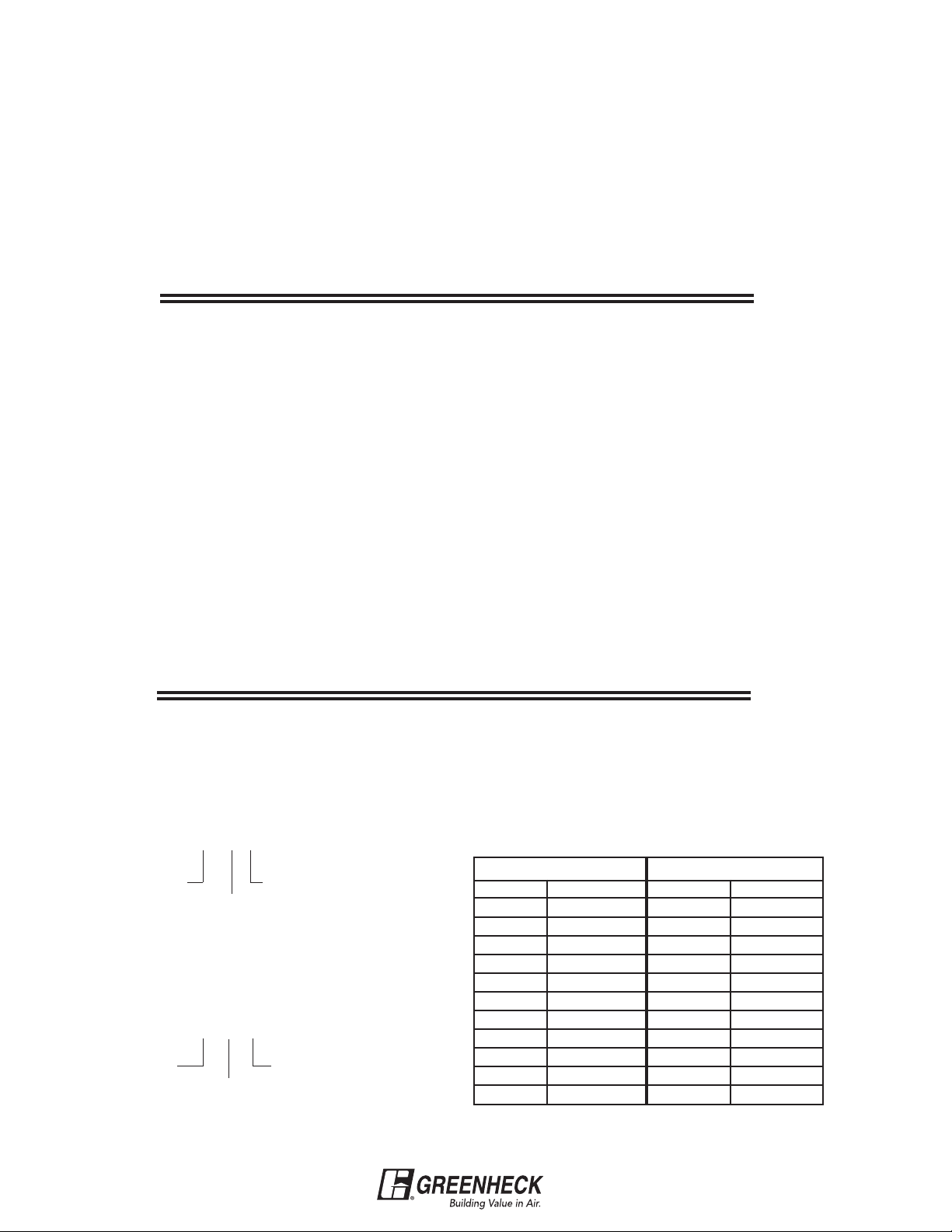
The table below lists model designation suffixes for
motor horsepower and fan rpm.
Belt Drive
Suffix Motor hp Suffix Fan rpm
6
4
3
5
7
10 1 E 1050
15 11/2 F 680
20 2 P 1625
30 3
50 5
75 71/2
1
/6 A 1725
1
/4 B 1140
1
/3 C 860
1
/2 D 1550
3
/4 G 1300
Direct Drive
Page 5
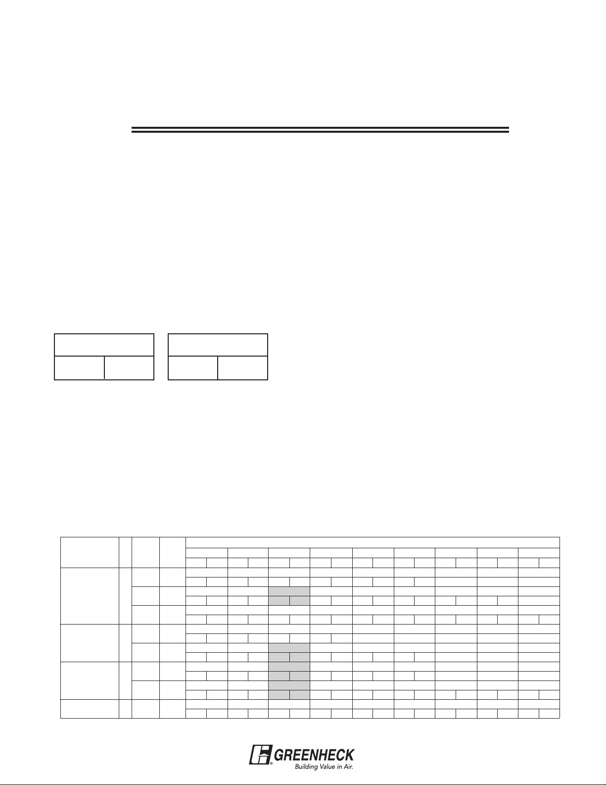
Reading Performance Charts
The most important part of selecting a fan is the ability
to read the performance charts. Most of the
performance charts in the catalog are similar and are
read in the same manner. Models RSF and BCF are
Belt Drive Selection
Assume that a job requires a belt drive roof exhauster
to move 1000 cfm against 0.25 in. Ps. Refer to the
performance model at the bottom of this page. Start at
the top of the chart with the 0.25 in. Ps column. (All
numbers in this column correspond to .25 in. Ps.) Now
follow the column downward until a value is found that
slightly exceeds 1000 cfm. In this case, 1012 cfm is the
first box that meets the requirements.
Note: Notice that each performance box is divided into
3 smaller boxes. The numbers refer to cfm, Sones and
Bhp.
Example:
CFM
Sone Bhp
At this performance point, the sone value is 11.1 and
the fan Bhp required is 0.16. Now by following the row
to the left, we can determine fan rpm and fan model.
In this case, the fan rpm is 1510 and the model is
GB-090-4 which has a 1/4 hp motor.
Notice that the GB-090-4 is not the only model to
choose from. If we follow the 0.250 in. Ps column down
further, we find a performance point at 1010 cfm.
1012
11.1 0.16
exceptions to this rule. The selection procedure for
these models is handled separately. Direct drive and
belt drive fans are also addressed separately.
At this point, the sone value is 7.9 and the Bhp is 0.14.
Following across to the left we find the rpm to be 1355.
The model is GB-101-4-R1, which also has a 1/4 hp
motor.
Both the GB-090-4 and the GB-101-4-R1 will perform
the air movement task equally as well. However, the
sound generated by the fan may have to be
considered. Compare the sone values: 7.9 sones for the
GB-101 and 11.1 for the GB-090. The GB-101 is about
30% quieter. Where a low sound fan is required, the
GB-101 would be a better selection. If loudness is not a
factor, the GB-090 would be a better selection because
it is less expensive.
Another possibility for this particular selection is a
GB-100-4-R2. Even though there is no performance
box showing close to 1000 cfm, there are two
performance boxes that bracket 1000 cfm. At 921 cfm
the fan will be running at 1260 rpm. At 1269 cfm the fan
will be running at 1635 rpm. Therefore, there is an rpm
for this model that will correspond to 1000 cfm
(obviously somewhere within the 1260-1635 rpm
range). As with all Greenheck belt drive fans,
intermediate cfm values are easily achieved by
adjusting the motor pulley (see illustration on next
page).
Table 2
MODEL
(rpm RANGE)
GB-090-4
(1290-1710)
GB-101-4-R1
(1020-1400)
GB-101-4-R2
(1260-1635)
GB-101-3
hp
1/4
1/4
1/4
1/3
RPM
1360 3983
1510 4422
1710
1070 3116
1355 3946
1260
1635
1800 5242
TS
5008
3669
4761
STATIC PRESSURE / CAPACITY
0.000 0.125 0.250 0.375 0.500 0.625 0.750 0.875 1.000
Sone Bhp Sone Bhp Sone Bhp Sone Bhp Sone Bhp Sone Bhp Sone Bhp Sone Bhp Sone Bhp
1030
10.1 0.11 9.9 0.12 9.6 0.12 9.3 0.12 8.8 0.13 8.5 0.13
1144
0.15 11.2 0.16 11.1 0.16 10.7 0.17 10.4 0.17 10.0 0.17 9.8 0.17 9.5 0.17
11.4
1295 1237 1179 1121 1061 999 934 866 785
13.4 0.22 13.3 0.23 13.2 0.23 13.0 0.24 12.7 0.24 12.4 0.25 12.1 0.25 11.8 0.25 11.6 0.25
906
6.0 0.060 5.4 0.065 5.0 0.070 4.3 0.070
1148 1077 1010 943 856 739
0.12
8.5
1067 991 921 840 735 385
0.099 7.1 0.104 6.8 0.112 6.5 0.115 5.9 0.115 4.4 0.083
7.6
1385 1325 1269 1214 1161 1094 1019 928 792
11.1 0.22 10.8 0.22 10.4 0.23 10.2 0.24 9.8 0.25 9.3 0.25 8.9 0.25 8.4 0.25 7.8 0.24
1525 1471 1418 1367 1320 1270 1208 1141 1064
0.29
13.2
8.1
12.8
957
1078
818
0.13
0.30
884
1012 946 875 800 720 607
731
7.9 0.14 7.8 0.14 7.2 0.14 6.8 0.14
0.30
12.5
807
607
0.31 12.2 0.33 11.3 0.33 10.8 0.33 10.6 0.33 10.1 0.33
12.3
725
632
5
Page 6
One advantage of choosing the GB-101-4-R2 over the
GB-101-4-R1 is that it is capable of running at higher
rpm’s, which enables the fan to move more air if
necessary.
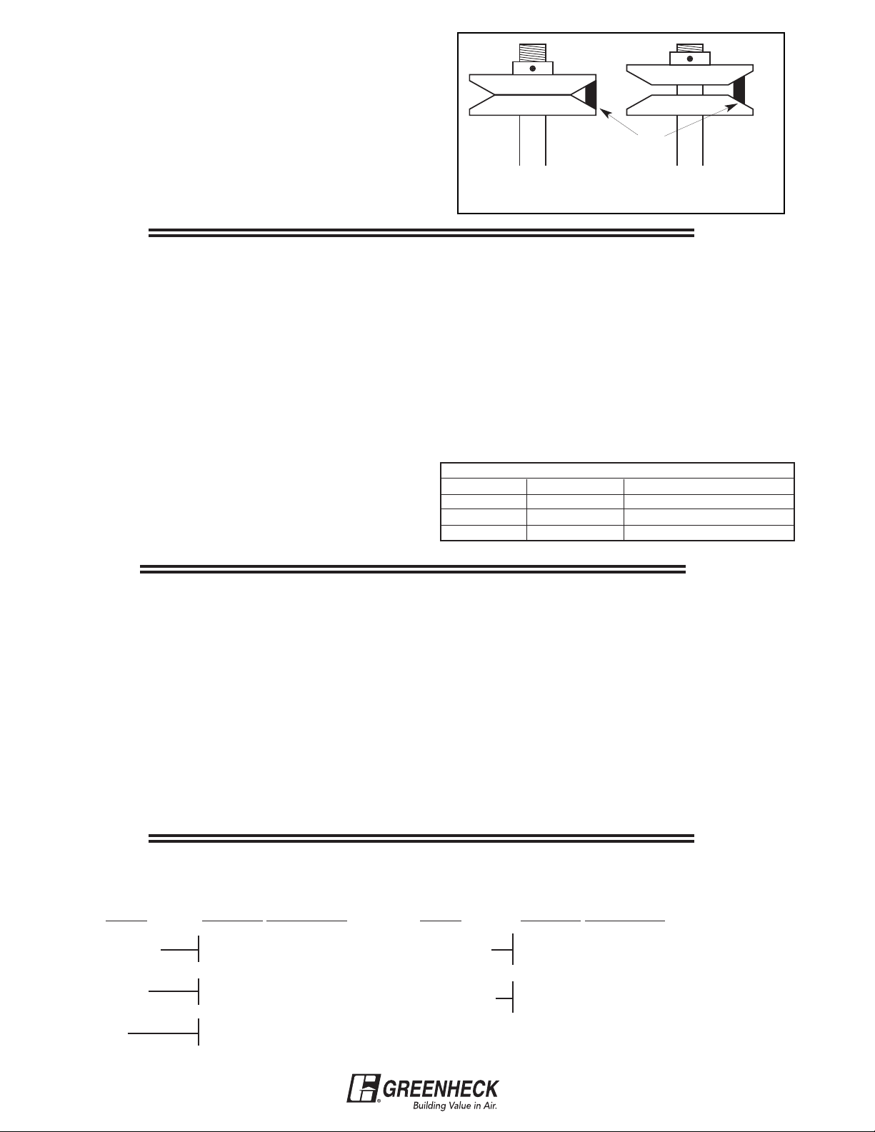
Motor pulleys are adjusted by loosening the set screw
and turning the top half of the pulley (see illustrations at
right). This causes the pulley diameter to change, which
results in changing the fan rpm.
Direct Drive Selection
Selection of direct drive fans (those with the motor shaft
connected to the fan wheel or propeller) is nearly the
same as belt drive selection. However, there are two
differences worth noting. Where belt drive fan speed
can be altered by adjusting the motor pulley, direct
drive fans (since they have no pulleys) must use a
different method.
1. To adjust a direct drive fan's speed (also motor
speed) or to provide a means of meeting an exact
performance requirement, a speed control can be
furnished. Speed controls vary the voltage supplied
to the fan and slows it down; a principle similar to
the way dimmer light switches work.
Belt
Opening the pulley decreases fan rpm.
Closing the pulley increases fan rpm.
2. Models CUE and CW, sizes 060-095 and Model SQ,
sizes 60-95, are provided with 115 volt, 60 cycle
motors. The three speeds are 1550 rpm (D), 1300
rpm (G) and 1050 rpm (E). Changing a motor lead is
all that is necessary to change speeds. When
selecting a model with 3 speed motors, it is
recommended that the G speed be chosen whenever
possible. This is the middle speed, which gives the
greatest flexibility in air volume because airflow can
be increased or decreased simply by changing a
motor lead.
Typical Motor Tag
Electrical Instructions
Suffix Letter Motor Speed Wiring Connections
D 1550 rpm White to L1 Black to L2
G 1300 rpm White to L1 Blue to L2
E 1050 rpm White to L1 Red to L2
Motor Information (Belt Drive Only)
When specifying a belt drive fan, the model designation
does not completely describe the unit. Additional
information about the motor is necessary. These items
are listed below:
Motor Enclosure
This will be either “Open” (open, drip proof), “TE”
(totally enclosed) or “EXP” (explosion resistant). Open
is the most common and will be supplied unless
otherwise specified.
Speeds
Motors are available in either single speed or two
speed. Single speed motors are 1725 rpm. Two speed
motors will be 1725/1140 rpm. Single speed will be
supplied unless otherwise specified.
Electrical Characteristics
Voltage and phase. Voltage can be 115, 208, 230 or
460. Phase is either single or 3 phase. A 115 volt, single
phase motor is shown as 115/1. Typically, motors of
1/2 hp and less are single phase. Motors of 3/4 hp and
greater are 3 phase.
Accessories
Most fans are ordered with accessories. Here are some common accessories for selected models:
Model Common Accessories
G & GB
CUBE
SB
Roof Curb
Backdraft Damper
Roof Curb
Grease Trap
Wall Mount Housing or
Wall Mount Collar
Model Common Accessories
SP & CSP
SQ & BSQ
Speed Control
Discharge Vents
Backdraft Damper
Vibration Isolators
6
Page 7
Matching a Specification
There will be times when a Greenheck model will have
to be matched to a competing manufacturer’s unit. To
aid in these circumstances, we have provided a cross
reference chart which includes our nine most common
competitors. If the manufacturer you need is not on this
chart, contact Greenheck for assistance.
To use the cross reference chart, on next page, start
with the manufacturer at the top. Then follow down
until the model in question is found. Follow across to
the left to determine which Greenheck model is
equivalent. Once this is determined, refer to the
Greenheck catalog to find the best size to meet the
specified performance.
Hint: Typically, when matching a Greenheck fan to a
competitive model, the size should also be matched. If
you are unsure of the size of the competitive unit,
compare fan rpm. Fans of equal size should move
approximately the same amount of air.
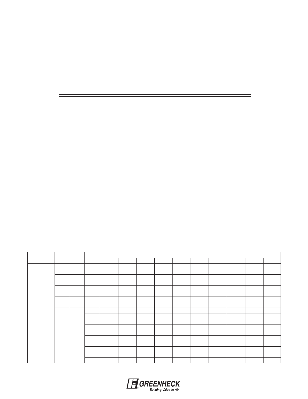
Model RSF and BCF Selection
The RSF and BCF selection charts are different from all
other selection charts. For these models, the cfm
values are at the left side of the chart in a single column
and the rpms are in the performance boxes. It is just the
opposite for other models. The reason for this is that
the RSF and BCF models are forward curved, and the
fan industry historically catalogs forward curved fans in
this fashion.
Sample problem:
Choose the fan size and appropriate motor horsepower
to move 980 cfm against 0.625 in. Ps.
Solution: (Refer to table below)
The first row in the chart corresponds to 980 cfm.
Follow across to the right to the 0.625 in. Ps column.
The performance box reveals that size 90 will meet this
performance at 893 rpm and will require 0.20 Bhp.
Motor hp selection for forward curved fans is more
complicated. The Bhp is only 0.20, which suggests that
a 1/4 hp motor is adequate. However, forward curved
fans draw more horsepower at low Ps than at high Ps.
Assume this fan was running at about 893 rpm, but
instead of 0.625 in. Ps, it was operating at only 0.25 in.
Ps. The new performance box in the 0.25 in. Ps column
reveals 894 rpm at 0.45 Bhp. The airflow would then be
1860 cfm.
Notice that as the Ps was reduced from 0.625 in. to 0.25
in., the Bhp increased from 0.20 to 0.45. This would
burn out the 1/4 hp motor quickly. With this in mind, it is
good practice to size RSF and BCF motors at least one
size larger than necessary based on the Bhp value in
the performance box, especially if the estimated Ps is
questionable.
For this case, an RSF-90-3 (1/3 hp motor) would be a
good selection if we had confidence in the estimated
Ps. Otherwise, use an RSF-90-5 (1/2 hp motor).
RSF-90-4 (1/4 hp motor) is not recommended for this
job.
MODEL
RSF-90
RSF-100
CFM
980 1065
1200
1420 1543
1640 1783
1860 2022
2080 2261
1240 1097
1780
2140
OV
1304
1575
1894
rpm
Bhp
rpm
Bhp
rpm
Bhp
rpm
Bhp
rpm
Bhp
rpm
Bhp
rpm
Bhp
rpm
Bhp
rpm
Bhp
STATIC PRESSURE / CAPACITY
0.125 0.250 0.375 0.500 0.625 0.750 1.000 1.250 1.500 1.750
521 630 725 812 893 967
0.08 0.11 0.13 0.16 0.20 0.23
593 685 771 849 925 994 1125
0.13
668
0.19 0.23 0.27 0.31 0.35 0.39 0.48 0.57 0.67
746 819 887 953 1016 1077 1191 1298
0.28
828 894 954 1014 1073 1128 1236
0.40 0.45 0.50 0.55 0.60 0.65 0.76
910 970 1027 1080 1134
0.54 0.60 0.66 0.71 0.77
476 572 656 733 807 876
0.10
605 679 748 813 873 931 1040 1143 1240
0.24 0.29 0.33 0.38 0.42 0.47 0.56 0.66 0.77
699
0.40 0.45 0.50 0.56 0.61 0.67 0.78 0.89 1.00 1.12
0.16 0.19 0.23 0.26 0.30 0.38
747
0.33
0.13
763
825
0.37
0.16
823 880 935 989 1086 1181 1269 1354
898
0.42 0.46 0.51 0.61 0.71
0.19
966
0.23
1031
0.27
1153
1267 1371
7
Page 8
Cross Reference Chart
(Models in italics refer to older models)
Greenheck
G
CE,CX,CH
GB
CDE, CBX
Cook
Updated 12-7-2004
ACED
C-D,CVD,TCD
ACEB
C-B,TCB,UCB
Penn Acme
Domex DX
XQ,XR,AT,AW
Domex DXB
KB,JB,MB,AB,LB
PRN CRD VEDK
PN,PNN,PV NBCR
CUE ACRUD, VCRD Fumex FX PDU n/a VUDK CUD, UBD n/a DU
CUBE
UCBE,UCBH
CW
SW,GW
CWB
GWB
ACRUB,VCR
URB,R-B,BTD
ACWD
CW
ACWB
CWB,TWB
SP Gemini GC Zephyr
CSP Gemini Inline GN Zephyr
SQ
DSQ,SQD
SQID,SQND
CV-D
BSQ SQIB,SQNB,
Fumex FXB
FMXB
Fumex WFX
Domex
WX,WA,WB
Fumex WFXB
Domex WCB,WLB
PNU
PUB,PU,PUH
PDU-W
PW
PNU-W
PWB
VQ/VQL J,EC,L VCDB,VCDC,
Z, (RA,TD)
VQ/VQL n/a VCDB IL DCF n/a
Z, (TDA)
Centrex SX XD ISD
Centrex SX-BC XB ILB VIBK
SQN-HP
SE/SS
SDE
SWD
SD
P FQ GDW
SCE/SCS AWD BC FN n/a LRDA,LNDA CDC HV, HVE
SBE/SBS
SPFE/SPFS
SBE/SBS-3
SPNE/SPNS
XLW,XMW
SWB SPB
BBK,BFL DC TBW LWBK,LMBK
XLWH,XMWH BF DCH LBW LJDB, LKDB,
SBCE/SBCS AWB BC,BAT DCK, K HBW LRBA,LNBA CBC HA
RBS/RBE
RPE,RPS
HXSL, HXSM,
HXEL, HXEM
AF EC/EC-S n/a LTBA,LGBA PB n/a n/a
RBCE/RBCS HEE,HES AC EC, ECH HBRE,HBRS n/a PBC n/a n/a
RE/RS HEE-D/HES-D AF n/a n/a LTDA,LGDA PD n/a n/a
RBU
PBU,PUB
LEU, LXUL, LXUM
AVB,VB
HF,HS,HZ
(cast)
UBG BRU LUBA JBH,JBC
RBUMO SUBH, SUB HX UBH available LUKA n/a RUBDX
RDU AUD HZ,HC UD DRU LUDA JDC UP
RSF ASP
CFS
Muffan MU AFSN
PLS
RSFP ASP-T n/a AFSL n/a VHBB n/a n/a n/a
SFD CPF-D n/a FCE FCD n/a n/a UDF n/a
SFB CPF-B n/a FCF, FCD,
FCA
SWB CPV,CPS Dynamo D,QX
GWB
QBR JVS VBBA VSBC UXB BI
Jenn
(Breidert)
(Stanley)
Carnes
VEDB,VEDC
VEBK
BCR
NBTD
NBRTD
VEBC
VUBK,VRBK
VUBB,URBA
CWD VWDK
VWDB
NBTD
NBRTD (UL 762)
VWBK
VWBB
VCDD
VIDK
ILD
VIDB,AMDA
COOLAIR
(ILG)
AirMaster
(Chelsea)
CRD CDD
RDD
CRB
LSB
UBC,CUB
CVB
CWD
CWF
CBD
RDB
CBU
CUBA
CDU
WDC
CWB CBU
WBC
CF NCF
CF
SQDA
CLD
n/a CVIDK
Captive Aire
DR
DD
NCA
DU
NCA
CFA
SQBA SBCL CVIBK
VIBA
HDW,FDW
LYDK,LZDK
LWDA
UDU/UDFPVEPR
WFA
C-EPR
n/a
PLFA
TYPE T
CBL,CBHPFHA
IND, FHA
CPB
CBHX n/a n/a
LRDA, LNDA
n/a
IND
(cast)
UPB
RUBA
CUPB
n/a
(cast)
CUPD
RUDA
BCFS VSBB
VSBA
CFS CAS n/a
FCB VFBA VSFC UXF n/a
(Flow Air)
Competitor Model Number Deciphering Hints
Cook-
Direct Drive
120 W 10 D
Direct Drive
rpm x 100
Model ACW
Wheel Size
Letter Designations
C=ACE (G,GB)
R=ACRU (CUBE)
W=ACW (CW,CWB)
V=VCR (CUBE)
Belt Drive
150 V 6 B
Belt Drive
3/4 hp
Model VCR
Wheel Size = 15 in.
Horsepower Designations
/4
3
=1/6 hp
2
3=1/4
4=1/3
=1/2
5
=
6
7=1
8=1
=
9
1
/2
2
8
=
0
1
11=5
12=7
Acme -
Direct Drive
PW 135 A 8
860 rpm
1/20 hp
Wheel Size =13.5 in.
Model PW
Direct Drive rpm Designation
3
1
/2
8 = 860 rpm
6 = 1160 rpm
4 = 1725 rpm
Belt Drive
PNN 163 G
1/2 hp
Wheel Size = 16.3 in.
Model PNN
Horsepower Designation
1/20 hp
=
A
B=1/12
C=1/8
1/6
=
D
E=1/4
=
F
G=1/2
H=3/4
=
J
K=1
1/3
1
2
=
L
M=3
N=5
1
7
=
/2
P
1
/2
R=10
Page 9

FAN SELECTION BASED ON FAN APPLICATION
Basic Overview
Ventilating a building simply replaces stale or foul air
with clean, fresh air. Although the ventilation process is
required for many different applications, the airflow
fundamentals never change:
Undesired air out, fresh air in
The key variables that do change depending on
applications are the fan model and the air volume flow
rate (cfm). Other considerations include the resistance
to airflow (static pressure or Ps) and sound produced
by the fan (Sones).
Fan specification is usually not a precise science and
can be done confidently when the fan application is
understood.
Based on the application, four parameters need to be
determined. They are:
1. Fan Model
2. cfm
3. Static Pressure (Ps)
4. Loudness limit (sones)
Occasionally, a customer will require a fan to perform a
particular function, yet does not know which model to
use or even what cfm is necessary. In this case, some
fan specification work must be done.
Fan Model
Fans all perform the basic function of moving air from
one space to another. But the great diversity of fan
applications creates the need for manufacturers to
develop many different models. Each model has
benefits for certain applications, providing the most
economical means of performing the air movement
function. The trick for most users is sorting through all
of the models available to find one that is suitable for
their needs. Here are some guidelines.
The information that follows will help walk you through
this type of problem and enable you to select the right
fan for the job.
Propeller vs. Centrifugal Wheel
Propeller fans provide an economical method to move
large air volumes (5,000+ cfm) at low static pressures
(0.50 in. or less). Motors are typically mounted in the
airstream which limits applications to relatively clean
air at maximum temperatures of 110°F.
Centrifugal fans are more efficient at higher static
pressures and are quieter than propeller fans. Many
centrifugal fan models are designed with motors
mounted out of the airstream to ventilate contaminated
and high temperature air.
Direct Drive vs Belt Drive
Direct drive fans are economical for low volume (2000
cfm or less) and low static pressure (0.50 in. or less).
They require little maintenance and most direct drive
motors can be used with a speed control to adjust the
cfm.
Belt drive fans are better suited for air volumes above
2000 cfm or static pressures above 0.50 in..Adjustable
pulleys allow fan speed and cfm to be adjusted by
about 25%. High temperature fans (above 120°F) are
almost always belt driven.
Fan Location
Fan models are designed to be mounted in three
common locations: on a roof, in a wall, or in a duct.
Whatever the location, the basic fan components do
not change. Only the fan housing changes to make
installation as easy as possible.
Determining the best location for a fan depends on the
airflow pattern desired and the physical characteristics
of the building. By surveying the building structure and
visualizing how the air should flow, the place to locate
the fan usually becomes evident.
Examples of fans installed in common applications are
illustrated on the following 6 pages. Even if you come
across an application that is not shown in this manual,
the concepts remain the same.
9
Page 10

Commercial Kitchen Ventilation
Recommended Exhaust Fans
Model CUBE Model USGF Model CWB Model SWB
Belt Drive Belt Drive Belt Drive Belt Drive
Upblast Roof Exhaust Upblast Roof Exhaust Sidewall Exhaust Utility Blower
300-30,000 cfm 300-7,000 cfm 300-12,000 cfm 500-30,000 cfm
Up to 5.0 in. wg Up to 3 in. wg Up to 2.75 in. wg Up to 5.0 in. wg
The above models are designed for exhausting dirty or grease laden air up and away from the roof line or away
from the wall in commercial restaurant applications. All three models are UL 762 listed for restaurant applications
and for operation with air temperatures up to 300°F.
Recommended Supply Fans
Model DG
Direct Gas-Fired
Make-Up Air
800-15,000 cfm
Up to 2.0 in. wg
Model RSF
Filtered Roof Supply
650-14,300 cfm
Up to 2.0 in. wg
Model IG
Indirect Gas-Fired
Make-Up Air
800-7,000 cfm
Up to 2.0 in. wg
Model BSQ Model SQ
Belt Drive Inline Direct Drive Inline
150-28,000 cfm 120-5,000 cfm
Up to 4.0 in. wg Up to 1.75 in. wg
Model TCB
Belt Drive Inline Fan
Roof Upblast, Supply
360-24,000 cfm
Up to 4.5 in. wg
The above models are designed to provide efficient economical make-up air to replenish the air exhausted
through the kitchen hood. Provisions for make-up air must be considered for proper kitchen ventilation.
10
Page 11

Commercial Kitchen Ventilation
This drawing shows a commercial kitchen with a typical
kitchen ventilation system consisting of a roof mounted
CUBE upblast exhaust fan and a Model RSF supply fan.
Exhaust fan variations include the model CWB sidewall
exhaust fan (also shown) when penetrating the roof is not
practical. The Model SWB utility blower is recommended
when higher static pressure capability is required to pull
exhaust through long duct runs (typically 3 stories or
more).
Fan Sizing
Exhaust
When not specified by local codes, the following guidelines may be used
to determine the minimum kitchen hood exhaust cfm. Some local codes
require 100 cfm/ft.2 of hood area for wall style hoods.
Supply
Recommended supply airflow is 90% of
exhaust cfm. The remaining 10% of
supply air will be drawn from areas
adjacent to the kitchen, which helps
prevent undesirable kitchen odors from
drifting into areas such as the dining
room.
NFPA Considerations
The National Fire Protection Association specifies
minimum distance criteria for restaurant exhaust and
supply fans as shown below:
10 ft. Horizontal Separation
1. Roof deck to top of exhaust fan windband - 40 in. min.
2. Roof deck to top of curb - 18 in. min.
3. Supply fan intake - 10 ft. min. from all exhaust fans.
3 ft. Horizontal Separation
For applications where the 10 ft. horizontal distance
cannot be met, vertical separation between exhaust and
supply must be at least 3 feet.
Light Duty Oven, Range, Kettle 50
Medium Duty Fryer, Griddle 75
Heavy Duty Charbroiler, Electric Broiler 100
Static pressure typically ranges from .625 in. to 1.0 in. for 1 story buildings.
Type of Cooking Equipment cfm/ft.2 of Hood
11
Page 12

General Commercial Ventilation
Model G
Direct Drive Roof Exhaust
90-3,200 cfm
Up to 1.0 in. wg
Model GB
Belt Drive Roof Exhaust
80-44,700 cfm
Up to 3.25 in. wg
The above models are designed for exhausting relatively clean air at temperatures up to 130°F. Motors
are out of the airstream. Direct drive sizes 60-95 are equipped with 3-speed motors for maximum airflow
flexibility. All direct drive units except 1725 rpm (A speed) can be used with a speed control.
Model CW
Direct Drive Wall Exhaust
80-6,000 cfm
Up to 2.25 in. wg
Model CWB
Belt Drive Wall Exhaust
300-12,000 cfm
Up to 2.75 in. wg
Model SP
Ceiling Exhaust Fan
50-1,600 cfm
Up to 1.0 in. wg
Model CSP
Inline Cabinet Fan
100-3,800 cfm
Up to 1.0 in. wg
Models SP and CSP are designed for exhausting relatively
clean air at temperatures up to 110°F. Motors are in the
airstream. All models are direct drive and can be used with
a speed control.
Model BSQ
Belt Drive Inline Fan
150-28,000 cfm
Up to 4.0 in. wg
Model SQ
Direct Drive Inline Fan
120-5,000 cfm
Up to 1.75 in. wg
Models SQ and BSQ are versatile
fans that can be used for exhaust
or supply and can be mounted in
any position. Two removable side
panels provide access for service.
12
Page 13

Typical Commercial Ventilation Installations
13
Page 14

Model SB
Belt Drive
Propeller Sidewall
3,600-85,000 cfm
Up to 1.0 in. wg
General Industrial Ventilation
Model RBU
Belt Drive
Propeller Upblast
4,000-65,000 cfm
Up to 1.0 in. wg
Model RB
RBS-Supply
RBE-Exhaust
RBF-Filtered
Belt Drive Propeller Roof
2,000-86,500 cfm
Up to 1.5 in. wg
Model RBUMO
Belt Drive
Propeller Upblast
3,000-60,000
Up to 1.0 in. wg
Typical Applications
Propeller fans are ideal for ventilating high air volumes at low static pressures (0.50 in. or less). Industrial
applications often include factories and warehouses. A variety of fan models offer flexibility for roof or wall mount
as well as exhaust or supply. However, because the motors are mounted in the airstream, these models are not
recommended for temperatures above 110°F.
14
Page 15

High Static Pressure Ventilation
Model SWB
Belt Drive Utility Blower
500-30,000 cfm
Temperatures up to 400°F
Up to 5.0 in. wg
Model BSQ
Belt Drive Inline Fan
150-28,000 cfm
Temperatures up to 180°F
Up to 4.0 in. wg
Typical Applications
Models SWB and BSQ are general, all-purpose fans that are capable of moving high air volumes
against high static pressures (up to 5.0 in wg). High static pressures are generated by long or complex
duct systems, especially when capture hoods are present. Both models can be used for either exhaust
or supply. Model SWB is designed to be mounted indoors or outdoors, while model BSQ can be used
indoors only.
15
Page 16

Determining CFM (cfm)
After the model is known, the cfm must be determined.
Consult local code requirements or the table below for
suggested air changes for proper ventilation.
The ranges specified will adequately ventilate the
corresponding areas in most cases. However, extreme
conditions may require “Minutes per Change” outside
of the specified range. To determine the actual number
needed within a range, consider the geographic
location and average duty level of the area. For hot
Suggested Air Changes for Proper Ventilation
climates and heavier than normal area usage, select a
lower number in the range to change the air more
quickly. For moderate climates with lighter usages,
select a higher number in the range.
To determine the cfm required to adequately ventilate
an area, divide the room volume by the appropriate
“Minutes per Change” value.
cfm =
Area Min./Chg. Area Min./Chg. Area Min./Chg.
Assembly Hall 3-10 Dance Hall 3-7 Machine Shop 3-6
Attic 2-4 Dining Room 4-8 Mill 3-8
Auditorium 3-10 Dry Cleaner 2-5 Office 2-8
Bakery 2-3 Engine Room 1-3 Packing House 2-5
Bar 2-4 Factory 2-7 Projection Room 1-2
Barn 12-18 Foundry 1-5 Recreation Room 2-8
Boiler Room 1-3 Garage 2-10 Residence 2-6
Bowling Alley 3-7 Generator Room 2-5 Restaurant 5-10
Cafeteria 3-5 Gymnasium 3-8 Rest Room 5-7
Church 4-10 Kitchen 1-5 Store 3-7
Classroom 4-6 Laboratory 2-5 Transfer Room 1-5
Club Room 3-7 Laundry 2-4 Warehouse 3-10
Sample problem:
A building requires an exhaust fan to ventilate a general
office (see diagram below) which measures 30 ft. x 40
ft. x 8 ft. The office is often crowded.
Solution:
The total room volume is 30 ft. x 40 ft. x 8 ft. = 9600
cubic feet. From the chart, the range for general offices
is 2-8 minutes per change. Since the office has heavier
than normal usage, 4 minutes per change is
recommended. Therefore, the required exhaust is:
9600 ft
4 min.
Room Volume
Min./Chg.
3
= 2400 cfm
Room Volume = L x W x H (of room)
Since the air to be exhausted is relatively clean, this is
an ideal application for a model GB fan.
Note: In this example, make-up air was provided
through a set of louvers at the wall farthest from the
exhaust fan. If there were no provisions for make-up air
in this room, a supply fan would also have to be sized.
The supply cfm should equal the exhaust cfm. Supply
fan location should be as far as possible from the
exhaust fan.
16
Page 17

Determining Static Pressure (Ps)
The pressures generated by fans in ductwork are very small.
Yet, accurately estimating the static pressure is critical to
proper fan selection.
Fan static pressure is measured in inches of water gauge.
One pound per square inch is equivalent to 27.7 in. of water
gauge. Static pressures in fan systems are typically less
than 2 in. of water gauge, or 0.072 Psi. The drawing to the
right illustrates how static pressures are measured in
ductwork with a manometer.
A pressure differential between the duct and the atmosphere
will cause the water level in the manometer legs to rest at
different levels. This difference is the static pressure
measured in inches of water gauge.
In the case of the exhaust fan at right, the air is being drawn
upward through the ductwork because the fan is producing
a low pressure region at the top of the duct. This is the same
principle that enables beverages to be sipped through a straw.
The amount of static pressure that the fan must overcome depends on the air velocity in the ductwork, the number
of duct turns (and other resistive elements), and the duct length. For properly designed systems with sufficient
make-up air, the guide lines in the table below can be used for estimating static pressure:
Exhaust Fan
STATIC PRESSURE GUIDELINES
Non-Ducted 0.05 in. to 0.20 in.
Ducted 0.2 in. to 0.40 in. per
100 feet of duct (assuming duct
air velocity falls within 1000-1800
feet per minute)
Fittings 0.08 in. per fitting
(elbow, register, grill, damper, etc.)
Kitchen Hood Exhaust 0.625 in. to 1.50 in.
Important: Static pressure requirements are significantly affected
by the amount of make-up air supplied to an area. Insufficient
make-up air will increase static pressure and reduce the amount of
air that will be exhausted. Remember, for each cubic foot of air
exhausted, one cubic foot of air must be supplied.
To calculate the system losses, one must know the
ductwork system configuration (see Ductwork figure).
This duct is sized for air velocities of 1400 feet per minute.
Referring to the static pressure chart, that will result in
about 0.3 in. per 100 feet. Since we have 10 feet of total
ductwork, our pressure drop due to the duct is:
.3 in.
100 ft.
There is also a 0.08 in. pressure drop for each resistive
element or fitting. For this example, there are 5 fittings:
x 10 ft. = .03 in.
Ductwork
one grill, two duct turns, one damper and louvers in
the wall of the office. The total pressure drop for
fittings is:
5 x 0.08 in. = 0.4 in.
Therefore, the total pressure drop is:
0.03 in. + 0.40 in. = 0.43 in.
For convenience in using selection charts, round this
value up to the nearest 1/8 in., which would be 0.50 Ps.
17
Page 18

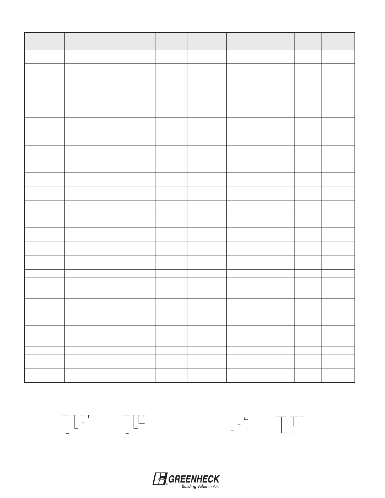
Preliminary Selections
At this point we know the model, cfm and Ps. With this
information we can refer to the GB performance charts
to determine the sizes available to move 2400 cfm
against 0.50 in. Ps.
In our case, all of the criteria can be met by more than
one size of a particular model. When this occurs,
choose the size that provides the greatest airflow range
about the desired cfm. For example, many direct drive
fans have three speeds. If possible, choose a size that
uses the middle rpm. This will allow some final system
adjustment if the actual cfm the job requires is
somewhat higher or lower once the fan is installed. Belt
driven fans have adjustable motor pulleys which allow
the fan speed to be varied. With belt drive units, avoid
Stability Considerations
Whenever there is more than one size to choose from,
it is not recommended to select from the performance
box in the far right column for any given rpm unless the
Ps is known to be accurate. For example, the GB-200
selection (see table below) of 2493 cfm at 0.50 in. Ps is
the far right selection at 700 rpm.
selecting near the maximum rpm of a size to allow for
final adjustments if necessary.
There are four GB sizes to choose from in the QD
catalog. These sizes along with their performance data
are in the table below.
Model and
Size
Performance Box Data
CFM Sones Bhp
RPM
GB-141 2556 16.8 .76 1545
GB-161 2614 13.5 .53 1100
GB-180 2375 8.6 .35 810
GB-200 2493 7.8 .40 700
The next box to the right (0.625 in. Ps) is empty
because the performance at that point is unstable. This
means that 2494 cfm at 0.50 in. is marginally stable.
For more information on fan stability, contact
Greenheck.
MODEL
(rpm RANGE)
GB-141-5
(1125-1360)
GB-141
GB-161-4
(634-865)
GB-161-5
(852-1100)
GB-180-3
(618-810)
GB-180-5
(700-940)
GB-180-7
(764-1055)
GB-180
GB-200-5
(512-770)
RPM
hp
1/2
1360 5207
3/4
1545 5915
1/4
1/2
1100 4787
1/3
1/2
1000 4843
3/4
1055 5109
1185 5739
1
1335 6465
11/2
1460 7071
2
1/2
Tip
Speed
785 3416
865 3764
985 4287
770 3729
810 3923
900 4359
940 4553
700 3917
770 4308
STATIC PRESSURE / CAPACITY
0.000 0.125 0.250 0.375 0.500 0.625 0.750 0.875 1.000
Sone Bhp Sone Bhp Sone Bhp Sone Bhp Sone Bhp Sone Bhp Sone Bhp Sone Bhp Sone Bhp
2522 2433 2346 2258 2166 2062 1942 1792 1602
14.6 0.48 14.3 0.50 13.9 0.51 13.5 0.52 13.1 0.52 12.7 0.52 12.2 0.53 11.6 0.52 11.0 0.51
2866 2787 2709 2634 2556 2475 2384 2286 2176
17.6 0.71 18.0 0.72 17.4 0.74 17.1 0.75 16.8 0.76 15.9 0.77 14.9 0.77 14.8 0.77 14.7 0.78
2318 2104 1875 1587
8.9 0.18 8.5 0.19 8.3 0.19 7.8 0.19
2555 2359 2162 1932 1624
10.6 0.24 10.1 0.25 9.7 0.26 9.4 0.26 8.8 0.25
2909 2737 2567 2382 2176 1914 1550
0.35
13.4
3249
15.3 0.48 14.7 0.50 14.1 0.52 13.8 0.53 13.5 0.53 13.0 0.53 12.5 0.52 12.0 0.50
2994 2833 2651 2427 2139 1700
8.1 0.25 9.2 0.26 9.1 0.29 8.5 0.30 7.8 0.30 7.4 0.28
3150 2997 2832 2624 2375 2053
10.6 0.29 10.3 0.31 10.0 0.33 9.3 0.35 8.6 0.35 8.2 0.34
3500 3364 3219 3052 2858 2624 2347 1821
12.7 0.40 12.4 0.42 12.1 0.44 11.3 0.46 10.5 0.48 10.2 0.48 9.8 0.47 9.2 0.43
3655
13.6
0.46 13.4 0.47 13.1 0.49 12.3 0.52 11.4 0.54 11.0 0.55 10.6 0.54 10.1 0.52
3888
15.2
0.55 14.7 0.57 13.7 0.58 13.3 0.62 13.0 0.64 12.4 0.66 11.9 0.66 11.6 0.65 11.1 0.63
4102
16.2
0.65 15.7 0.67 14.9 0.68 14.4 0.72 14.0 0.74 13.5 0.76 12.9 0.77 12.7 0.77 12.4 0.77
4607
19.0
0.91 18.4 0.94 17.8 0.96 17.4 0.98 17.1 1.03 16.7 1.05 16.2 1.07 15.8 1.10 15.4 1.10
5191
22.0
1.31 22.0 1.33 21.0 1.36 21.0 1.37 21.0 1.41 20.0 1.47 19.9 1.49 19.5 1.51 19.2 1.54
5677
26.0
1.71 25.0 1.74 24.0 1.77 24.0 1.79 24.0 1.81 24.0 1.86 23.0 1.93 23.0 1.95 23.0 1.97
3873
0.39
10.3
4260
0.52
12.1
0.36
12.7
3094
3527 3388 3234 3052 2844 2601 2272
3768 3638 3504 3339 3164 2952 2712 2387
3989 3866 3741 3596 3432 3251 3050 2811
4507 4400 4290 4179 4045 3900 3753 3575
5102 5010 4912 4814 4715 4599 4474 4343
5595 5514 5424 5335 5245 5155 5049 4938
3591
0.40
9.6
4013
0.53
11.0
0.37 11.9 0.38 11.5 0.38 10.9 0.37 10.2 0.35
12.3
2943 2786 2614 2428 2197 1899
3307 2973 2493
0.41
9.2
3744
0.55
10.7
8.6
10.2
0.41
3477
0.55
7.8
9.8
3140
0.40
0.55
2643
9.3 0.52
18
Page 19

Sound Levels
In many cases, the sound generated by a fan must be
considered. For the fan industry, a common unit for
expressing sound pressure level is the sone. In
practical terms, the loudness of one sone is equivalent
to the sound of a quiet refrigerator heard from five feet
away in an acoustically average room.
Sones are a linear measurement of sound pressure
levels. For example, a sound level of 10 sones is twice
as loud as 5 sones.
Refer to the Suggested Limits for Room Loudness chart
to determine the acceptable sone range for the
application. As a general guideline, choose a fan that
has a sone value within the range specified.
Note: Rooms with a hard construction (concrete block,
tile floors, etc.) reflect sound. For these rooms, select
fans on the lower end of the range. Rooms with soft
construction or those with carpeting and drapes, etc.,
absorb sound. For these rooms, fans near the higher
end of the range may be selected.
Our example describes an exhaust fan for an office.
Referring to the “Suggested limits for Room Loudness”
chart, offices should have a loudness range from 4 to
12 sones. Of our remaining three selections, only the
GB-180 has a sone value of less than 12. Therefore, the
GB-180 is the best selection for this application.
Suggested Limits for Room Loudness
Sones DBA
1.3-4 32-48 Private homes (rural and suburban)
1.7-5 36-51 Conference rooms
2-6
2.5-8
3-9 44-60 Court rooms, museums,
4-12 48-64 Restaurants, lobbies,
5-15 51-67 Corridors and halls, cocktail lounges,
7-21 56-72 Hotel kitchens and
12-36 64-80 Light machinery, assembly lines
15-50 67-84 Machine shops
25-60 74-87 Heavy machinery
From AMCA Publication 302 (Application of Sone Ratings
for Non Ducted Air Moving Devices with Room-Sone-dBA
correlations).
38-54 Hotel rooms, libraries,
movie theatres, executive offices
41-58 Schools and classrooms,
hospital wards, and operating rooms
apartments, private homes urban)
general open offices, banks
washrooms and toilets
laundries, supermarkets
Motor Horsepower
The motor horsepower for direct drive fans is always
sized by Greenheck and does not require further
consideration. For belt drive models, the catalog
identifies which horsepower is recommended.
However, there are times when it is wise to bump the
horsepower one size. For example, the hp
recommended for the GB-180 at 810 rpm is 1/3 hp.
Although a 1/3 hp motor is recommended, it is not
necessarily a good motor selection for this application.
Our static pressure of 0.5 in. was only an estimate. It
may actually turn out to be .625 in.
If this is the case, we will need a 1/2 hp motor because
our fan will have to run at almost 900 rpm (refer to
performance box - 2624 cfm at 0.625 in.Ps). Therefore,
choosing a 1/2 hp motor in this case is exercising good
judgement.
The complete model designation for this application is
GB-180-5.
Note: The GB-180-5 has an rpm range of 700-940
(refer to model column in catalog). This means
that if the static pressure is less than estimated,
say 0.25 in. Ps, the fan can be slowed down to
accommodate this condition.
19
Page 20

Installation
To ensure proper fan performance as cataloged,
caution must be exercised in fan placement and
connection to the ventilation system. Obstructions,
transitions, poorly designed elbows, improperly
selected dampers, etc., can cause reduced
performance, excessive noise, and increased
mechanical stressing. For the fan to perform as
published, the system must provide uniform and stable
airflow into the fan.
Uniform Flow Improperly sized or
obstructed damper
Wheel Rotation
A common problem is wheel rotation in the wrong
direction. For centrifugal fans, incorrect wheel rotation
will provide some airflow. However, the airflow will be
far below the cataloged value. Rotation should be
checked while the fan is coasting to a stop. Proper
rotation for the most common wheels are shown below.
Elbow too close
to fan inlet
When connecting a 3 phase motor, there is a 50%
chance that the fan will run backwards. Changing any
two supply power connections will reverse the direction
of rotation.
20
Page 21

FAN PERFORMANCE
The first two sections of this guide contain information
needed to select the right fan for the particular
application. The information in this section is useful
once the fan has been selected and installed on the job.
The fan curves and system resistance curves below will
help to solve fan performance problems that may be
encountered in a variety of applications.
Fan Dynamics
A fan is simply an air pump. The rate at which a fan can
“pump” air depends on the pressure the fan must
overcome. This principle also relates to water pumps.
A water pump is able to deliver more water through a
2 in. diameter hose than a 1 in. diameter hose because
the 1 in. hose creates more resistance to flow.
For a fan, every flow rate (CFM-Cubic Feet per Minute)
corresponds to a specific resistance to flow (Ps-Static
Pressure). The series of cfm, Ps points for a fan at a
constant rpm is called a fan curve. A fan curve at 700
rpm is shown below.
Fan Curve Varying Fan Curve
At 0.25 in. Ps, this fan will deliver 1000 cfm. If the
pressure increases, cfm decreases. If the pressure
decreases, cfm will increase.
At 700 rpm, the operating point will slide along the fan
curve as static pressure changes, but it will never lie off
the curve. In order for a fan to perform at a point off the
curve, the rpm must be changed.
The figure below illustrates how rpm affects the fan
curve. Notice that the general shape of the curves are
the same. Changing rpm simply moves the curve
outward or inward.
System Dynamics
For a given flow rate (cfm), an air distribution system
produces a resistance to airflow (Ps). This resistance is
the sum of all static pressure losses as the air flows
through the system. Resistance producing elements
include ductwork, dampers, grills, coils, etc.
A fan is simply the device that creates the pressure
differential to move air through the system.
The greater the pressure differential created by the fan,
the greater the volume of air moved through the
system. Again, this is the same principle that relates to
water pumps. The main difference in our case is that
the fan is pumping air.
Tests have established a relationship between cfm and
Ps. This relationship is parabolic and takes the form of
the following equation:
Ps = K x (cfm)
Where K is the constant that reflects the “steepness” of
the parabola. This equation literally states that Ps
varies as the square of the cfm.
For example, whenever the cfm doubles, the Ps will
increase 4 times. The figures on the next page
graphically illustrate this concept.
2
21
Page 22

System Resistance Curve Varying System Resistance Curve
Sample problem:
If a system is designed to move 1000 cfm at a
resistance of 0.25 in. Ps, what static pressure would the
fan have to overcome to produce 2000 cfm of airflow?
Solution:
Since static pressure varies as the square of cfm, we
can solve for the new Ps (Ps
equation:
2
cfm
Ps2= Ps1x
(
cfm
2
= 0.25 in. x
)
1
2 ) with the following
2000cfm
(
1000 cfm
2
)
= 1.0 in.
Note: Physically changing the system will alter the
system resistance. For example, closing a
damper from 100% open to only 50% open will
add resistance and increase the “steepness” of
the system resistance curve. The same effect
occurs as filters become dirty. The figure above
illustrates this point.
Curve A defines a system that requires 0.5 in. Ps to
move 1000 cfm. Curve B requires 0.75 in. Ps to move
the same amount of air. This is typical of how a system
reacts to increased resistance.
Referring to the figure above, this results in sliding up
the system resistance curve from Point A to Point B.
For this system, it is impossible to move 2000 cfm at
only 0.25 in. Ps. For any given system, every cfm
requires a unique Ps. This series of cfm/Ps points
forms a system resistance curve such as the one
above. Once the system resistance curve is defined,
changing the fan rpm will change the cfm and Ps
simultaneously, which results in sliding along the
system resistance curve.
Combining Fan and System Dynamics
The previous two sections introduced fan curves and
system resistance curves. This section will show how
these relate to each other to provide an understanding
of the way the fan-system operates as a complete
entity.
In this section, there are three key points to emphasize:
1. As airflow through a system changes, so does the
static pressure.
2. For a steady-state system, operating points must
lie on the curve defining that system’s cfm/Ps
characteristics.
3. As the system’s resistive elements change, the
steepness of the system resistance curve changes.
Remember that a fan curve is the series of points at
which the fan can operate at a constant rpm. Likewise,
a system resistance curve is the series of points at
which the system can operate. The operating point
(cfm, Ps) for the fan-system combination is where these
these two curves intersect.
22
Page 23

The operating point of the fan and the system is
the point where these two curves intersect. This
intersection will determine the cfm and Ps
delivered.
Operating Point
Adjusting Fan Performance
There is a direct relationship between cfm and rpm
within a system. Doubling the fan rpm will double the
cfm delivered.
Sample problem:
The figure on page 21 showed a fan curve at 700 rpm
which had an operating point of 1000 cfm at 0.25 in. Ps.
What rpm is required to move 2000 cfm through the
same system?
Solution:
Within a system, cfm is directly related to rpm.
Therefore, the new rpm (rpm2) can be determined from
the following equation:
cfm
rpm2= rpm1X
X
1
2000 cfm
(
1000 cfm
rpm
(
rpm
700 rpm x
=
Referring to figure at right, this results in sliding up the
system resistance curve from 700 rpm to 1400 rpm.
Notice that as we doubled our airflow from 1000 cfm to
2000 cfm, the Ps went up from 0.25 in. to 1.0 in. It must
be kept in mind that we are not changing the system,
only increasing fan speed. Therefore, we must remain
on the system resistance curve. Within a system, Ps
varies as the square of cfm. Since cfm and rpm are
directly proportional, an equation relating Ps and rpm
can be derived as follows:
Ps
Ps2=
(
cfm
2
1
2
)
1
)
2
)
= 1400 rpm
Varying Operating Points
For our example,
rpm
2
= 1.0 in.
)
Ps2= 0.25 in. X
This verifies the operating point on the 1400 rpm curve
(2000 cfm at 1.0 in. Ps). With this example, it should be
clear how cfm, rpm and Ps tie together in a steadystate system.
1400 rpm
(
700
23
Page 24

Fan Laws
In a steady-state system, as the fan rpm changes, cfm, Ps
and BHp (horsepower) also change. The equations below,
known better as fan laws, show the relationship between
these performance parameters.
rpm
cfm
New
=
rpm
New
Old
x cfm
Old
Ps
Bhp
New
New
rpm
=
(
rpm
=
(
rpm
New
Old
rpm
New
Old
)
2
x Ps
3
)
Old
x Bhp
Old
The first two equations have already been covered in the fan
and system dynamics section. Refer to the examples in those
sections on how to apply these equations.
The third equation relates horsepower to rpm. The change in
horsepower can be determined when the rpm is increased by
25%. This is shown below:
Bhp
= (1.25)3x Bhp
New
= 1.95 x Bhp
Old
Old
NOTE: a 25% increase in rpm results in a 95% increase in
horsepower. Considering this, initial fan selections should be
sized with motor horsepowers greater than necessary if any
increase in fan rpm is likely in the future.
P.O. Box 410 • Schofield, WI 54476-0410 • Phone (715) 359-6171 • greenheck.com
Fan Fundamentals Rev 2 June 2005
Copyright © 2005 Greenheck Fan Corp.
 Loading...