

Page 1
Fan Fundamentals
Introduction to FAN SELECTION
This is a guide to the most basic fan sections, all of which enable you to select the right fan for the job. It will answer the
following questions (and more):
• What is a SONE?
• How are model numbers and performance tables used to select a fan?
• How are direct drive and belt driven fans different?
• What types of motors are used with these fans?
The goal is to understand and use the Greenheck literature as an important tool in filling a customer’s fan order.
TERMS
cfm Cubic Feet Per Minute. A measure of airflow.
Ps Static Pressure. Resistance to airflow measured in inches of water gauge.
sone
Bhp Brake Horsepower. A measure of power consumption. Used to determine the proper motor horsepower and wiring.
hp Horsepower. Used to indicate a fan’s motor size.
rpm Revolutions Per Minute. Measure of fan speed.
TS Tip Speed. The speed of the tip of a fan wheel or prop measured in feet per minute.
AMCA
MODEL DESIGNATION
For Greenheck belt drive models, the model designation
tells the model type, size and the motor hp.
EXAMPLE: GB-090-6
Model is GB hp is 1/6
Nominal Wheel Dia. 9 in.
For direct drive units, the model designation tells
the model type, the size and the motor/fan rpm.
EXAMPLE: G-121-B
Model is G rpm is 1140
Nominal Wheel Dia. 12 in.
MOTOR INFORMATION (Belt Drive Only)
When specifying a belt drive fan, the model designation
does not completely describe the unit. Additional
information about the motor is necessary. These items
are listed below:
MOTOR ENCLOSURE
This will be either “Open” (open, drip proof), “TE” (totally
enclosed) or “EXP” (explosion-resistant). Open is the
most common and will be supplied unless otherwise
specified.
DIRECT DRIVE
Selection of direct drive fans (those with the motor shaft
connected to the fan wheel or propeller) is nearly the
same as belt drive selection. However, there are two
differences worth noting. Where belt drive fan speed can
be altered by adjusting the motor pulley, direct drive fans
(since they have no pulleys) must use a different method.
1
Models CUE and CW, sizes 060-095 and Model SQ,
2
A measure of loudness. One sone can be approximated as the loudness of a quiet refrigerator at a distance of 5 feet. Sones
follow a linear scale, that is, 10 sones are twice as loud as 5 sones.
Air Movement & Control Association. A nationally recognized association which establishes standards for fan testing and
performance ratings. AMCA also license air volume and sound certified ratings.
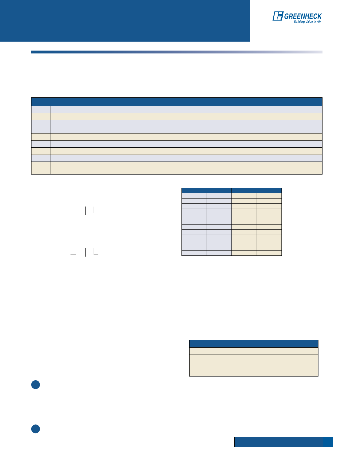
BELT DRIVE DIRECT DRIVE
Suffix Motor hp Suffix Fan rpm
6
4 ¼ B 1140
3
5 ½ D 1550
7 ¾ G 1300
10 1 E 1050
15 1½ F 880
20 2 P 1625
30 3
50 5
75 7½
1
/
6
1
/
3
A 1725
C 860
This table
lists model
designation
suffixes for motor
horsepower and
fan rpm.
SPEEDS
Motors are available in either single-speed or two speed.
Single-speed motors are 1725 rpm. Two speed motors
will be 1725/1140 rpm. Single-speed will be supplied
unless otherwise specified.
ELECTRICAL CHARACTERISTICS
Voltage and phase. Voltage can be 115, 208, 230 or 460.
Phase is either single-or 3 phase. A 115 volt, singlephase motor is shown as 115/1. Typically, motors of
1/2 hp and less are single-phase. Motors of 3/4 hp and
greater are 3 phase.
TYPICAL MOTOR TAG - Electrical Instructions
Suffix Letter Motor Speed Wiring Connections
D 1550 rpm White to L1 Black to L2
G 1300 rpm White to L1 Blue to L2
E 1050 rpm White to L1 Red to L2
To adjust a direct drive fan’s speed (also motor
speed) or to provide a means of meeting an exact
performance requirement, a speed control can be
furnished. Speed controls vary the voltage supplied to
the fan and slow
it down; a principle similar to the way dimmer light
switches work.
The three speeds are 1550 rpm (D), 1300 rpm (G) and 1050
rpm (E). Changing a motor lead is all that is necessary to
change speeds. When selecting a model with a 3 speed
motor, it is recommended that the G speed be chosen
whenever possible. This is the middle speed, which gives
the greatest flexibility in air volume because airflow can be
increased or decreased simply by changing a motor lead.
sizes 60-95, are provided with 115 volt, 60 cycle motors.
FAN FUNDAMENTAlS
129
Page 2
Introduction to FAN SELECTION
MOTOR HORSEPOWER
The motor horsepower for direct drive fans is
always sized by Greenheck and does not require
further consideration. For belt drive models,
the catalog identifies which horsepower is
recommended. However, there are times when it
is wise to bump the horsepower one size. For
example, the hp recommended for the GB-180
at 810 rpm (2375 cfm @ .5” Ps) is 1/3 hp.
Although a 1/3 hp motor is recommended, it is
not necessarily a good motor selection for this
application. Our static pressure of 0.5 in. was only
an estimate. It may actually turn out to be .625 in.
BELT DRIVE
One advantage of choosing a belt drive over a direct
drive is that it is capable of adjusting the fan rpm,
which enables the fan to move more air if necessary.
If this is the case, we will need a 1/2 hp motor
because our fan will have to run at almost
810 rpm (refer to performance box - 2052 cfm at
0.625 in. Ps). Therefore, choosing a 1/2 hp motor
in this case is exercising good judgement.
The complete model designation for this
application is GB-180-5.
NOTE: The GB-180-5 has an rpm range of 700-940.
This means that if the static pressure is less than
estimated, say 0.25 in. Ps, the fan can be slowed down
to accommodate this condition.
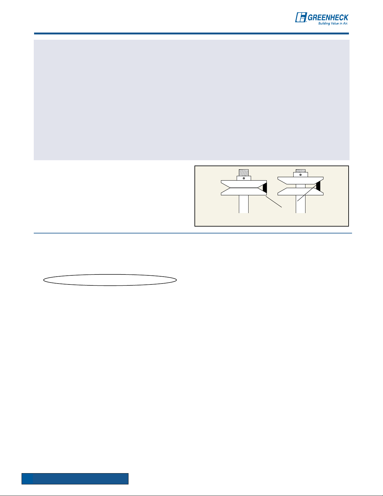
Motor pulleys are adjusted by loosening the set
screw and turning the top half of the pulley (see
illustrations at right). This causes the pulley diameter
to change, which results in changing the fan rpm.
APPLICATIONS
Ventilating a building simply replaces stale or foul
air with clean, fresh air. Although the ventilation
process is required for many different applications,
the airflow fundamentals never change:
UNDESIRED AIR OUT, FRESH AIR IN
The key variables that do change depending on
applications are the fan model and the air volume
flow rate (cfm). Other considerations include the
resistance to airflow (static pressure or Ps) and
sound produced by the fan (Sones).
Occasionally, a customer will require a fan to perform
a particular function, yet does not know which model
to use or even what cfm is necessary. In this case,
some fan specification work must be done.
Fan specification is usually not a precise science
and can be done confidently when the fan
application is understood.
Based on the application, four parameters need to
be determined. They are:
Fan Model
Cubic Feet per Minute (cfm)
Static Pressure (Ps)
Loudness limit (sones)
Belt
Opening the pulley decreases fan rpm.
Closing the pulley increases fan rpm.
The information that follows will help walk you
through this type of problem and enable you to
select the right fan for the job.
FAN MODEL
Fans all perform the basic function of moving air
from one space to another. But the great diversity of
fan applications creates the need for manufacturers
to develop many different models. Each model has
benefits for certain applications, providing the most
economical means of performing the air movement
function. The trick for most users is sorting through
all of the models available to find one that is
suitable for their needs.
PROPELLER vs. CENTRIFUGAL WHEEL
Propeller fans provide an economical method to
move large air volumes (5,000+ cfm) at low static
pressures (0.50 in. or less). Motors are typically
mounted in the airstream which limits applications to
relatively clean air at maximum temperatures of 110°F.
Centrifugal fans are more efficient at higher static
pressures and are quieter than propeller fans.
Many centrifugal fan models are designed with
motors mounted out of the airstream to ventilate
contaminated and high temperature air.
130
FAN FUNDAMENTAlS
Page 3

Exhaust fan to be sized
8 ft.
40 ft.
30 ft.
Louvers to supply
Makeup air
Introduction to FAN SELECTION
DETERMINING CFM
After the model is known, the cfm must be determined.
Consult local code requirements or the table below for
suggested air changes for proper ventilation.
The ranges specified will adequately ventilate the
corresponding areas in most cases. However,
extreme conditions may require “Minutes per
Change” outside of the specified range. To
determine the actual number needed within a range,
SUGGESTED AIR CHANGES FOR PROPER VENTILATION
Room Volume
Min./Chg.
Area Min./Chg. Area Min./Chg. Area Min./Chg.
Assembly Hall 3-10 Dance Hall 3-7 Machine Shop 3-6
Attic 2-4 Dining Room 4-8 Mill 3-8
Auditorium 3-10 Dry Cleaner 2-5 Office 2-8
Bakery 2-3 Engine Room 1-3 Packing House 2-5
Bar 2-4 Factory 2-7 Projection Room 1-2
Barn 12-18 Foundry 1-5 Recreation Room 2-8
Boiler Room 1-3 Garage 2-10 Residence 2-6
Bowling Alley 3-7 Generator Room 2-5 Restaurant 5-10
Cafeteria 3-5 Gymnasium 3-8 Restroom 5-7
Church 4-10 Kitchen 1-5 Store 3-7
Classroom 4-6 Laboratory 2-5 Transfer Room 1-5
Club Room 3-7 Laundry 2-4 Warehouse 3-10
cfm =
Room Volume = L x W x H (of room)
consider the geographic location and average duty
of the area. For hot climates and heavier than
level
normal area usage, select a lower number in the
range to change the air more quickly. For moderate
climates with lighter usages, select a higher number
in the range.
To determine the cfm required to adequately
ventilate an area, divide the room volume by the
appropriate “Minutes per Change” value.
SAMPLE PROBLEM
A building requires an exhaust fan to ventilate a
general office (see diagram below) which measures
30 ft. x 40 ft. x 8 ft. The office is often crowded.
SOLUTION:
The total room volume is 30 ft. x 40 ft. x 8 ft. = 9600
cubic feet. From the chart, the range for general
offices is 2-8 minutes per change. Since the office
has heavier than normal usage, 4 minutes per
change is recommended. Therefore, the required
exhaust is:
9600 ft
= 2400 cfm
4 min.
Since the air to be exhausted is relatively clean, this
is an ideal application for a model GB fan.
NOTE: In this example, make-up air was provided
through a set of louvers at the wall farthest from
the exhaust fan. If there were no provisions for
make-up air in this room, a supply fan would also
have to be sized. The supply cfm should equal the
exhaust cfm. Supply fan location should be as far
as possible from the exhaust fan.
3
FAN FUNDAMENTAlS
131
Page 4

Duct
Airflow
Atmospheric
Pressure
Manometer
Water
1 in.
Airflow out of
restaurant
Grill
Damper
Airflow to
exhaust fan
4 ft.
6 ft.
Introduction to FAN SELECTION
DETERMINING STATIC PRESSURE (Ps)
The pressures generated by fans in ductwork are
very small. Yet, accurately estimating the static
pressure is critical to proper fan selection.
Fan static pressure is measured in inches of water
gauge. One pound per square inch is equivalent
to 27.7 in. of water gauge. Static pressures in fan
systems are typically less than 2 in. of water gauge,
or 0.072 Psi. The drawing below illustrates how
static pressures are measured in ductwork with a
manometer.
A pressure differential between the duct and
the atmosphere will cause the water level in the
manometer legs to rest at different levels. This
difference is the static pressure measured in inches
of water gauge.
In the case of the exhaust fan below, the air is being
drawn upward through the ductwork because the
fan is producing a low pressure region at the top
of the duct. This is the same principle that enables
beverages to be sipped through a straw.
The amount of static pressure that the fan must
overcome depends on the air velocity in the
ductwork, the number of duct turns (and other
resistive elements), and the duct length. For
properly designed systems with sufficient make-up
air, the guidelines in the table below can be used for
STATIC PRESSURE GUIDELINES
estimating static pressure:
STATIC PRESSURE GUIDELINES
Nonducted 0.05 in. to 0.20 in.
0.2 in. to 0.40 in. per 100 feet of
Ducted
duct (assuming duct air velocity
falls within 1000-1800 feet per
minute)
Fittings
Kitchen Hood
Exhaust
Static pressure requirements are significantly affected
by the amount of make-up air supplied to an area.
Insufficient make-up air will increase static pressure
and reduce the amount of air that will be exhausted.
Remember, for each cubic foot of air exhausted, one
cubic foot of air must be supplied.
IMPORTANT!
0.08 in. per fitting (elbow, register,
grill, damper, etc.)
0.625 in. to 1.50 in.
Exhaust Fan
To calculate the system losses, one must know the
ductwork system configuration (see Ductwork figure).
This duct is sized for air velocities of 1400 feet per
minute. Referring to the static pressure chart, that will
result in about 0.3 in. per 100 feet. Since we have
10 feet of total ductwork, our pressure drop due to
the duct is:
.3 in.
100 ft.
x 10 ft. = .03 in.
Ductwork
There is also a 0.08 in. pressure drop for each
resistive element or fitting. For this example, there
are 5 fittings: one grill, two duct turns, one damper
and louver in the wall of the office. The total pressure
drop for fittings is:
5 x 0.08 in. = 0.4 in.
Therefore, the total pressure drop is:
0.03 in. + 0.40 in. = 0.43 in.*
132
* NOTE: For convenience in using selection charts, round this value up to the nearest 1/8 in., which would be 0.50 Ps.
FAN FUNDAMENTAlS
Page 5

Example
Solution
Introduction to FAN SELECTION
FAN LAWS
In a steady-state system, as the fan rpm changes, cfm, Ps and BHp (horsepower) also change. The equations
below, known better as fan laws, show the relationship between these performance parameters.
NOTE: A 25% increase in rpm results in a 95% increase in horsepower. Considering this, initial fan selections
should be sized with motor horsepowers greater than necessary if any increase in fan rpm is likely in the future.
rpm
cfm
Ps
Bhp
New
New
New
=
=
=
New
(
rpm
rpm
(
rpm
rpm
(
rpm
Old
New
Old
New
Old
)
)
ADJUSTING FAN PERFORMANCE
There is a direct relationship between cfm and rpm within a
system. Doubling the fan rpm will double-the cfm delivered.
Sample: The example at the right shows a fan curve at 700
rpm which had an operating point of 1000 cfm at 0.25 in. Ps.
What rpm is required to move 2000 cfm through the same
system?
Solution: Within a system, cfm is directly related to rpm.
Therefore, the new rpm (rpm2) can be determined from the
following equation:
rpm2= rpm1x
cfm2
(
cfm1
)
x
2
xPsOld
3
x
cfm
Bhp
Old
Old
]
This equation relates horsepower to rpm. The change in
horsepower can be determined when the rpm is increased by
25%. This is shown below:
Bhp
= (1.25)3x Bhp
New
For our example,
This verifies the operating point on the 1400 rpm curve
(2000 cfm at 1.0 in. Ps). With this example, it should be
clear how cfm, rpm and Ps tie together in a steady-state
system.
Old
Ps2= Ps1x
Ps2= 0.25 in. x
Varying Operating Points
= 1.95 x Bhp
(
1400 rpm
(
700 rpm
rpm2
rpm1
)
)
²
²
= 1.0 in.
)
Old
= 700 rpm x
Referring to figure at right, this results in sliding up the
system resistance curve from 700 rpm to 1400 rpm.
Notice that as we doubled our airflow from 1000 cfm to
2000 cfm, the Ps went up from 0.25 in. to 1.0 in. It must
be kept in mind that we are not changing the system, only
increasing fan speed. Therefore, we must remain on the
system resistance curve. Within a system, Ps varies as the
square of cfm. Since cfm and rpm are directly proportional,
an equation relating Ps and rpm can be derived as follows:
2000 cfm
(
1000 cfm
SOUND LEVELS
In many cases, the sound generated by a fan must be
considered. For the fan industry, a common unit for
expressing sound pressure level is the sone. In practical
terms, the loudness of one sone is equivalent to the sound
of a quiet refrigerator heard from five feet away in an
acoustically average room.
Sones are a linear measurement of sound pressure levels.
For example, a sound level of 10 sones is twice as loud as
5 sones.
SUGGESTED LIMITS FOR ROOM LOUDNESS
Sones DBA
1.3-4 32-48 Private homes (rural and suburban)
1.7-5 36-51 Conference rooms
2-6 38-54 Hotel rooms, libraries, movie theatres, executive offices
2.5-8 41-58 Schools and classrooms, hospital wards, and operating rooms
3-9 44-60 Courtrooms, museums, apartments, private homes (urban)
4-12 48-64 Restaurants, lobbies, general open offices, banks
5-15 51-67 Corridors and halls, cocktail lounges, washrooms and toilets
7-21 56-72 Hotel kitchens and laundries, supermarkets
12-36 64-80 Light machinery, assembly lines
15-50 67-84 Machine shops
25-60 74-87 Heavy machinery
From AMCA Publication 302 (Application of Sone Ratings for Non Ducted Air Moving Devices with
Room-Sone-dBA correlations).
1400 rpm
=
)
Refer to the Suggested Limits for Room Loudness chart to
determine the acceptable sone range for the application.
As a general guideline, choose a fan that has a sone value
within the range specified.
NOTE: Rooms with a hard construction (concrete block,
tile floors, etc.) reflect sound. For these rooms, select
fans on the lower end of the range. Rooms with soft
construction or those with carpeting and drapes, etc.,
absorb sound. For these rooms, fans near the higher end
of the range may be selected.
For example, an exhaust fan for an
office in the “Suggested Limits for Room
Loudness” chart below says that offices
should have a loudness range from 4 to 12
sones. Comparing a GB-141, GB-161 and
GB-180 fan for approximately 3100 cfm at
0” Ps only the GB-180 has a sone value of
less than 12. Therefore, the GB-180 is the
best selection for this application.
FAN FUNDAMENTAlS
133
 Loading...