

Page 1
Part # 464441
**WARNING**
Disconnect and secure all electrical power to the
“OFF” position prior to inspection or servicing.
Failure to comply with this safety precaution
could result in serious injury or death.
**IMPORTANT**
All factory provided lifting lugs must be used when lifting any unit. Failure to comply with this safety
precaution could result in property damage, serious injury or death.
FOR YOUR SAFETY
If you smell gas
1. Open windows
2. Don’t touch electrical switches
3. Extinguish any open flames
4. Immediately call your gas supplier
Report any damaged equipment to the shipper immediately!
All units are shipped on a skid or packaged to minimize damage during shipment. The transporting carrier has
the responsibility of delivering all items in their original condition as received from Greenheck. The individual
receiving the equipment is responsible for inspecting the unit for obvious or hidden damage, recording any
damage on the bill of lading before acceptance and filing a claim (if required) with the final carrier. Some
accessory items are stored inside the unit during shipping. Care must be taken during installation to prevent
damage to units.
FOR YOUR SAFETY
The use and storage of gasoline or other
flammable vapors and liquids in open
containers in the vicinity of this appliance
is hazardous.
**WARNING**
Improper installation, adjustment, alteration,
service or maintenance can cause property
damage, injury or death. Read the installation,
operating, and maintenance instructions
thoroughly before installing or servicing this
equipment.
MaintenanceTroubleshooting
OperationStart-UpInstallation
Reference
MODEL TSU
Make-Up Air Unit
Installation, Operation and Maintenance Manual
®
Page 2

TABLE OF CONTENTS
Installation
Unit - Slab Mounted . . . . . . . . . . . . . . . . . .I-1
Unit - Rail Mounted . . . . . . . . . . . . . . . . . . .I-2
Unit - Curb Mounted . . . . . . . . . . . . . . . . . .I-3
Filter Section / Weatherhood . . . . . . . . . . .I-5
Evaporative Cooler . . . . . . . . . . . . . . . . . . .I-6
Evaporative Cooling Piping . . . . . . . . . . . . .I-7
Water Wizard™ Evaporative Control . . . . .I-9
Electrical Wiring . . . . . . . . . . . . . . . . . . . . . .I-10
Direct Gas Piping . . . . . . . . . . . . . . . . . . . . .I-13
Building Pressure Control . . . . . . . . . . . . . .I-15
I
Start-Up
Blower . . . . . . . . . . . . . . . . . . . . . . . . . . . . .S-1
Direct Gas . . . . . . . . . . . . . . . . . . . . . . . . . .S-3
Evaporative Cooling . . . . . . . . . . . . . . . . . .S-9
Water Wizard™ Evaporative Controls . . . .S-11
S
Operation
Recirculating/VAV Units . . . . . . . . . . . . . . .O-1
Electrical . . . . . . . . . . . . . . . . . . . . . . . . . . .O-2
Water Wizard™ Evaporative Control . . . . .O-3
O
Troubleshooting
Blower . . . . . . . . . . . . . . . . . . . . . . . . . . . . .T-1
Heater . . . . . . . . . . . . . . . . . . . . . . . . . . . . .T-2
Vibration . . . . . . . . . . . . . . . . . . . . . . . . . . . .T-5
Evaporative Cooler . . . . . . . . . . . . . . . . . . .T-6
Water Wizard™ Evaporative Control . . . . .T-7
T
Reference
Gas Train Layout . . . . . . . . . . . . . . . . . . . . .R-1
Control Center Layout . . . . . . . . . . . . . . . . .R-2
Warranty . . . . . . . . . . . . . . . . . . . . . . . . . . . .R-2
Maintenance
Routine . . . . . . . . . . . . . . . . . . . . . . . . . . . . .M-1
Fall . . . . . . . . . . . . . . . . . . . . . . . . . . . . .M-4
Log . . . . . . . . . . . . . . . . . . . . . . . . . . . . .M-5
M
R
STORAGE
When a unit is not going to be in service for an extended period of time, certain procedures should be followed
to keep the unit in proper operating condition:
• Plug all piping
• Rotate fan wheel monthly and purge bearings once every one to three months (depending on environment).
• Energize fan motor once every three months
• Store belts flat to keep them from warping and stretching
• Store unit in location without vibration
• Cover unit with tarp to protect from dirt and moisture
• After storage period, purge grease before putting fan into service
NOTE!
Do not cover unit with a black tarp, this would
promote condensation.
NOTE!
Improper storage which results in damage to the
unit will void the warranty.
Page 3
Installation - Slab Mounted Unit
I - 1
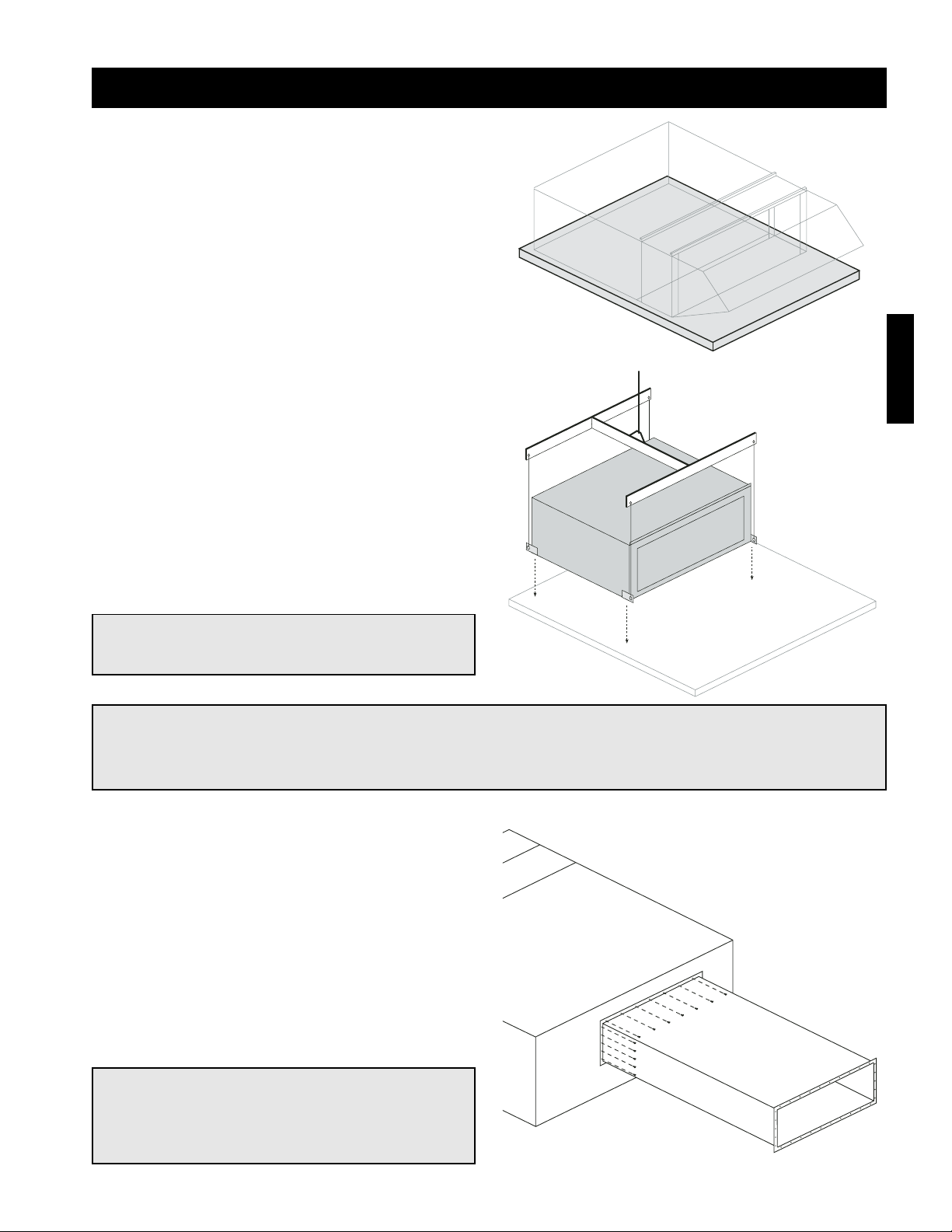
Step 1 Pour Concrete Slab
Pour the concrete slab. The slab should be one foot
larger than the unit on all sides. The slab should be at
least four inches thick and poured on a bed of gravel
to ensure proper drainage. Allow the concrete slab to
properly cure before installing the unit.
NOTE!
Good duct practices should be followed for all
ductwork. Ductwork should be installed in
accordance with SMACNA and AMCA guidelines,
NFPA 96 and any local codes.
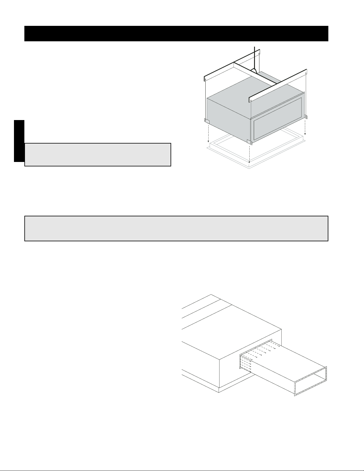
Step 2 Install Unit
Use a crane and a set of spreader bars hooked to the
factory lifting lugs to lift and center the unit on the
concrete slab. Fasten the unit to the slab through the
factory provided lifting lugs.
NOTE!
The use of all lifting lugs and a set of spreader
bars is mandatory when lifting the unit.
Step 3 Attach Ductwork
Refer to the CAPS submittal for the duct size and
location. Greenheck recommends attaching ductwork
using a rubber duct section at the unit to reduce
vibration. An appropriate sealant should be used
around the discharge opening of the unit to create a
weather tight seal.
total unit si
Recommen
thick.
Slab should
of gravel fo
NOTE!
For easy installation, it is recommended that the weatherhood, filter section or evaporative cooler be
installed after the base unit.
Page 4
I - 2
NOTE!
The use of all lifting lugs and a set of spreader
bars is mandatory when lifting the unit.
Installation - Rail Mounted Unit
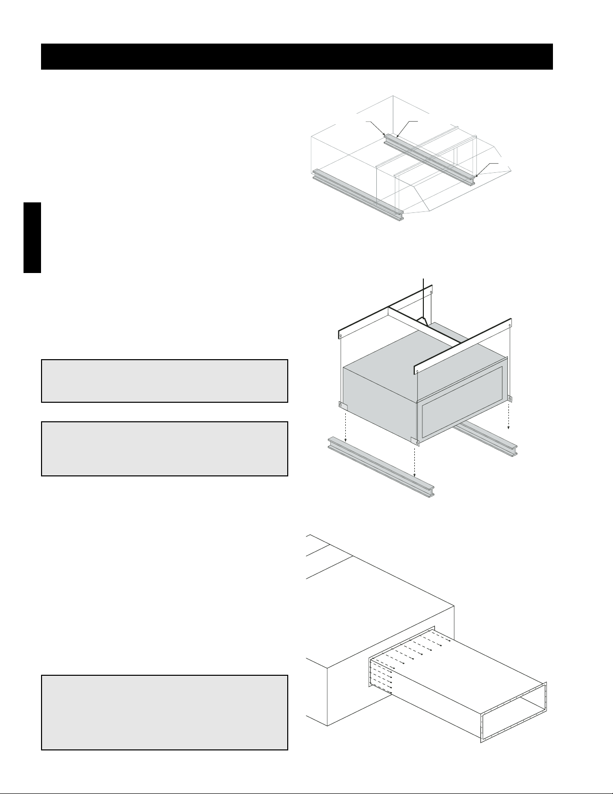
Step 1 Install Rails
Install the rails. The rails should be located 6 - 12
inches in from the sides of the unit. The rails should
extend at least six inches past the intake and
discharge ends of the unit. Rails are field supplied by
other and are not supplied by Greenheck.
Step 1 Rail Mountin
For proper support, rails s
6-12 in. in from sides of un
at least 6 in. beyond both
and filter section.
Rails located 6-12 in. in
from sides of unit.
Rails extends 6 in. from
end of filter section
Rails extends 6 in. from
discharge end of unit
Step 2 Install Unit
Use a crane and a set of spreader bars hooked to the
factory lifting lugs to lift and center the unit on the
rails.
NOTE!
Good duct practices should be followed for all
ductwork. Ductwork should be installed in
accordance with SMACNA and AMCA guidelines,
NFPA 96 and any local codes.
NOTE!
For easy installation, it is recommended that the
weatherhood, filter section or evaporative cooler
be installed after the base unit.
Step 3 Attach Ductwork
Refer to the CAPS submittal for the duct size and
location. Greenheck recommends attaching ductwork
using a rubber duct section at the unit to reduce
vibration. An appropriate sealant should be used
around the discharge opening of the unit to create a
weather tight seal.
Page 5
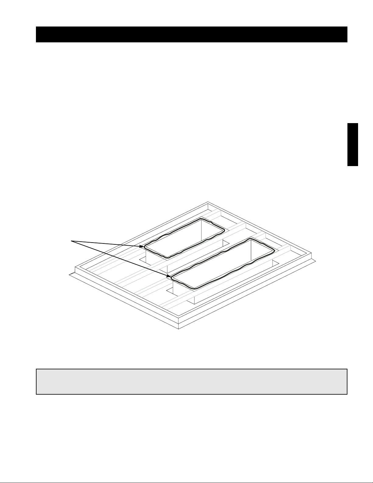
Step 3 Apply Sealant
Apply an appropriate sealant around the perimeter of the curb and duct adapter(s) to isolate fan vibration and
prevent water penetration.
Step 1 Install Curb
Position curb on the roof (refer to the CAPS submittal section for placement of curb in relation to the unit). Verify
that the curb is level, shim if necessary. Attach curb to roof and flash into place.
Step 2 Install Ductwork
If the unit has a downblast (DB) discharge, install the supply air duct now.
If the unit requires a return air duct, install it now.
If the unit has a horizontal (HZ) discharge, wait until the base unit is installed before installing the supply duct.
Good duct practices should be followed for all ductwork. All ductwork should be installed in accordance with
SMACNA and AMCA guidelines, NFPA 96 and all local codes. Refer to the CAPS submittal for the ductwork
sizes.
Installation - Curb Mounted Unit
I - 3
NOTE!
The use of a duct adapter is recommended on a downblast (DB) arrangement to align the ductwork
with the supply unit and is only a guide and is not to be used as ductwork support.
Sealant
Page 6
I - 4
Step 4 Install Unit
Use a crane and a set of spreader bars hooked to the
factory lifting lugs to lift and center the unit on the
curb.
Use self-tapping sheet metal screws to fasten the unit
to the curb.
NOTE!
The use of all lifting lugs and a set of spreader
bars is mandatory when lifting the unit.
NOTE!
For easy installation, it is recommended that the weatherhood, filter section or evaporative cooler be
installed after the base unit.
Step 5 Install Ductwork
If the unit has a downblast (DB) discharge, the
ductwork was installed in step 2.
If the unit has a horizontal (HZ) discharge, apply an
appropriate sealant around the discharge of the unit
to create a weather tight seal. Then using sheet metal
screws, attach the ductwork to the unit.
Good duct practices should be followed for all
ductwork. All ductwork should be installed in
accordance with SMACNA and AMCA guidelines,
NFPA 96 and all local codes. Refer to the CAPS
submittal for the ductwork sizes.
Installation - Curb Mounted Unit
Page 7
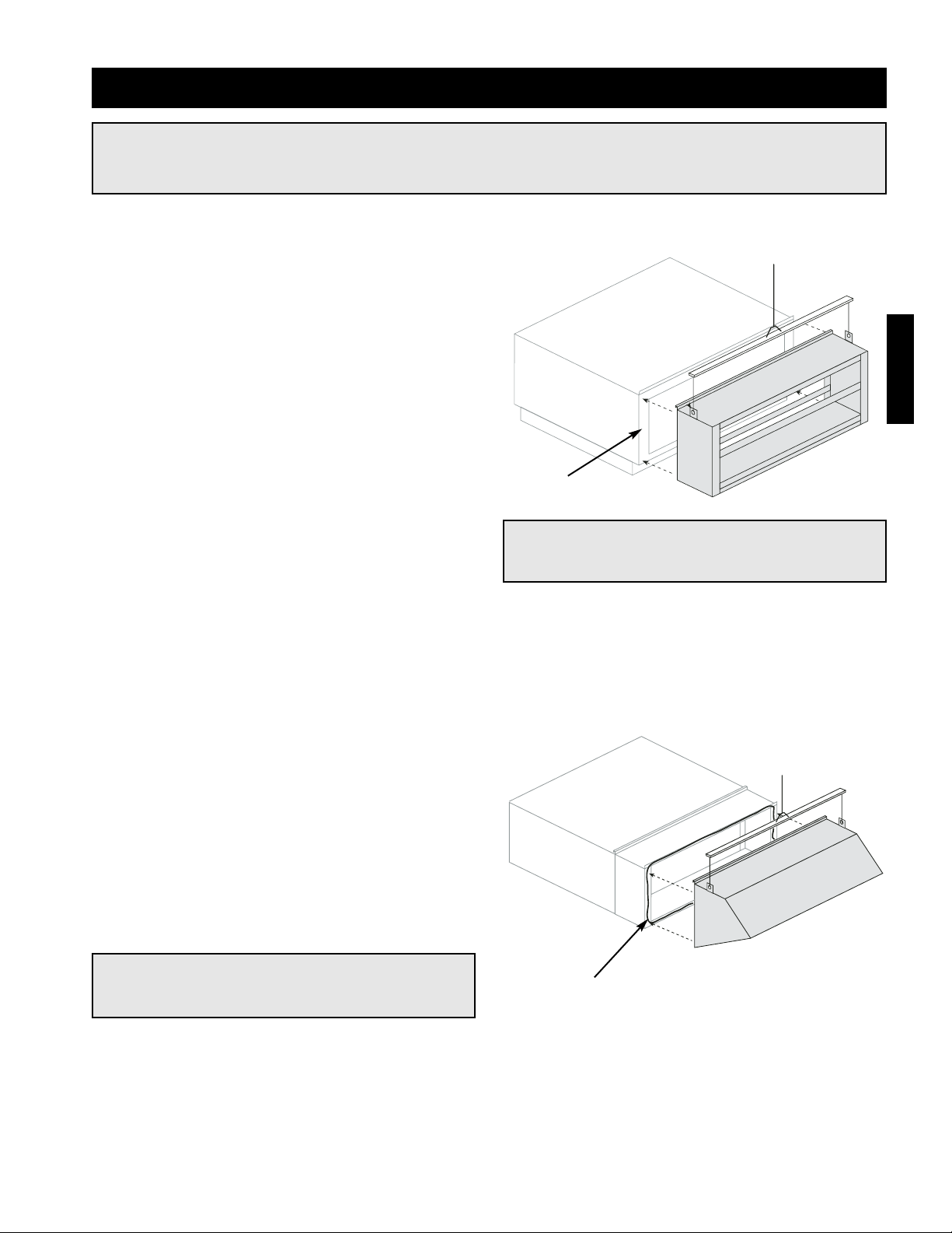
Installation - Filter Section and Weatherhood
Step 1 Apply Sealant
Apply an appropriate sealant around the intake end of
the base unit to create a weather tight seal.
Step 3 Apply Sealant
Apply an appropriate sealant around the intake end of the filter section to create a weather tight seal.
Step 2 Install Filter Section
Use a crane and a set of spreader bars hooked to the
factory lifting lugs to lift and center the filter section
on the intake end of the base unit. The flange along
the top of the filter section should overlap the flange
along the top of the base unit.
Use self-tapping sheet metal screws to fasten the
filter section to the base unit across the top and down
the sides.
If filters are not installed in the filter section, install
them now. Airflow arrows are located on the filters to
ensure proper installation.
Step 4 Install Weatherhood
Use a crane and a set of spreader bars hooked to the
factory lifting lugs to lift and center the assembled
weatherhood on the intake end of the base unit. The
flange along the top of the weatherhood should
overlap the flange along the top of the filter section.
Use self-tapping sheet metal screws to fasten the
weatherhood to the filter section across the top and
down the sides.
Step 5 Install Inlet Air Sensor (Optional)
If the unit is equipped with an inlet air sensor, the sensor may need to be installed. The sensor and tubing can be
found bundled inside the control center of the unit. The sensor should be installed inside of the weatherhood
with the tubing run inside of the unit.
NOTE!
The use of all lifting lugs and a set of spreader
bars is mandatory when lifting the filter section.
NOTE!
The use of all lifting lugs and a set of spreader
bars is mandatory when lifting the weatherhood.
NOTE!
Installation instructions for the filter section and weatherhood apply only to non-evaporative cooling
units. For evaporative cooling units, skip to the evaporative cooler installation instructions.
Sealant
Sealant
I - 5
Page 8
I - 6
NOTE!
When mounting the evaporative cooler, it is
important that it is level to ensure proper
operation and water drainage.
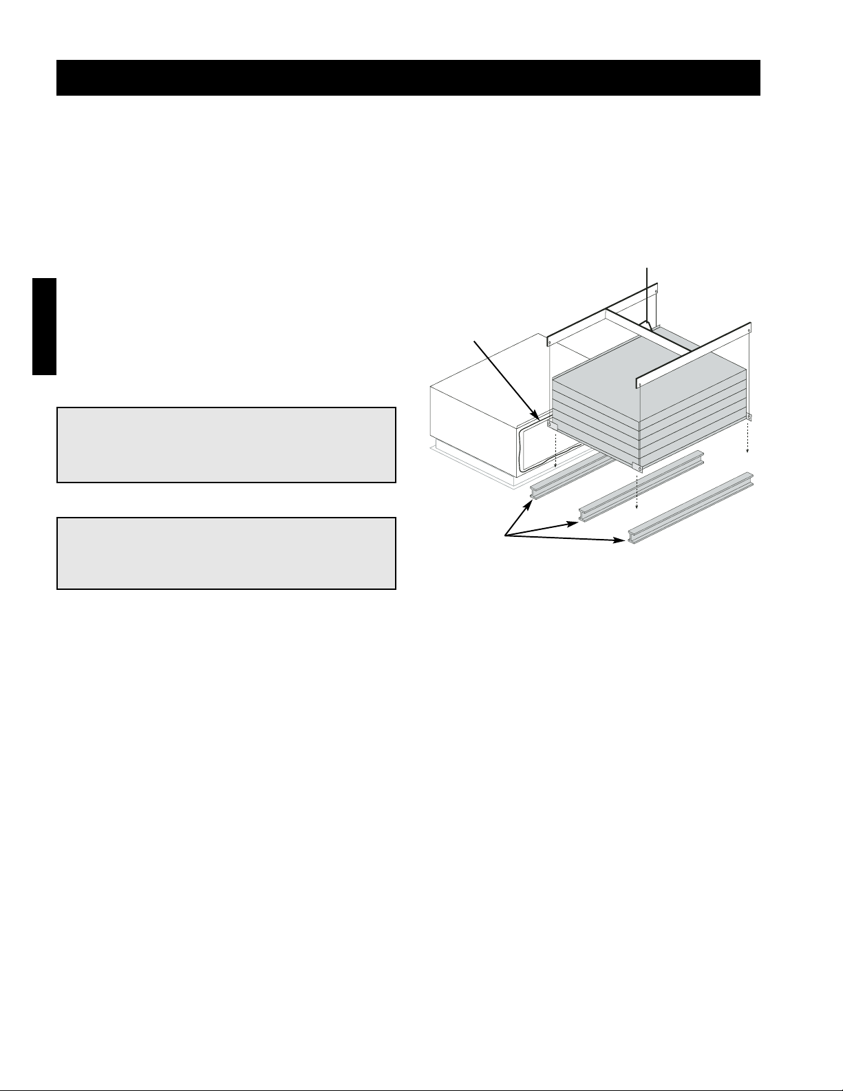
Installation - Evaporative Cooler (Optional)
Step 1 Locate Equipment Support(s)
Position equipment support(s) on the roof (refer to the CAPS submittal for the general location of the equipment
support(s) in relation to the unit). Verify that all unit supports are level, shim if necessary. Equipment supports
are supplied by others and not supplied by Greenheck.
Step 2 Install Evaporative Cooling
Module
Use a crane and a set of spreader bars hooked to the
factory lifting lugs to lift and center the evaporative
cooling module on the equipment support(s). The
flange along the top of the evaporative cooler should
overlap the flange along the top of the base unit.
Step 3 Secure Cooling Module to Unit
Use self-tapping screws to fasten the cooling module to the base unit. The cooler should be fastened to the
base unit across the top and down both sides.
To fasten along the top, run fasteners through the flange joining the two sections.
To fasten the sides, from inside the unit, run fasteners down both sides of the opening between the base unit
and the evaporative cooler.
Step 5 Connect Dirty Filter Switch (Optional)
If a dirty filter switch is located in the control center, connect the low pressure tap on the dirty filter switch to the
low pressure tap inside the junction box on the evaporative cooler. Tubing is included in the control center.
NOTE!
The use of all lifting lugs and a set of spreader
bars is mandatory when lifting the evaporative
cooling module.
Sealant
Equipment
Supports
Step 4 Install Inlet Air Sensor (Optional)
If the unit is equipped with an inlet air sensor, the sensor may need to be installed. The sensor and tubing can be
found bundled inside the control center of the unit. The sensor should be installed inside of the louvered intake,
upstream and clear of the evaporative cooling media. The tubing should be run inside of the unit.
Page 9
I - 7
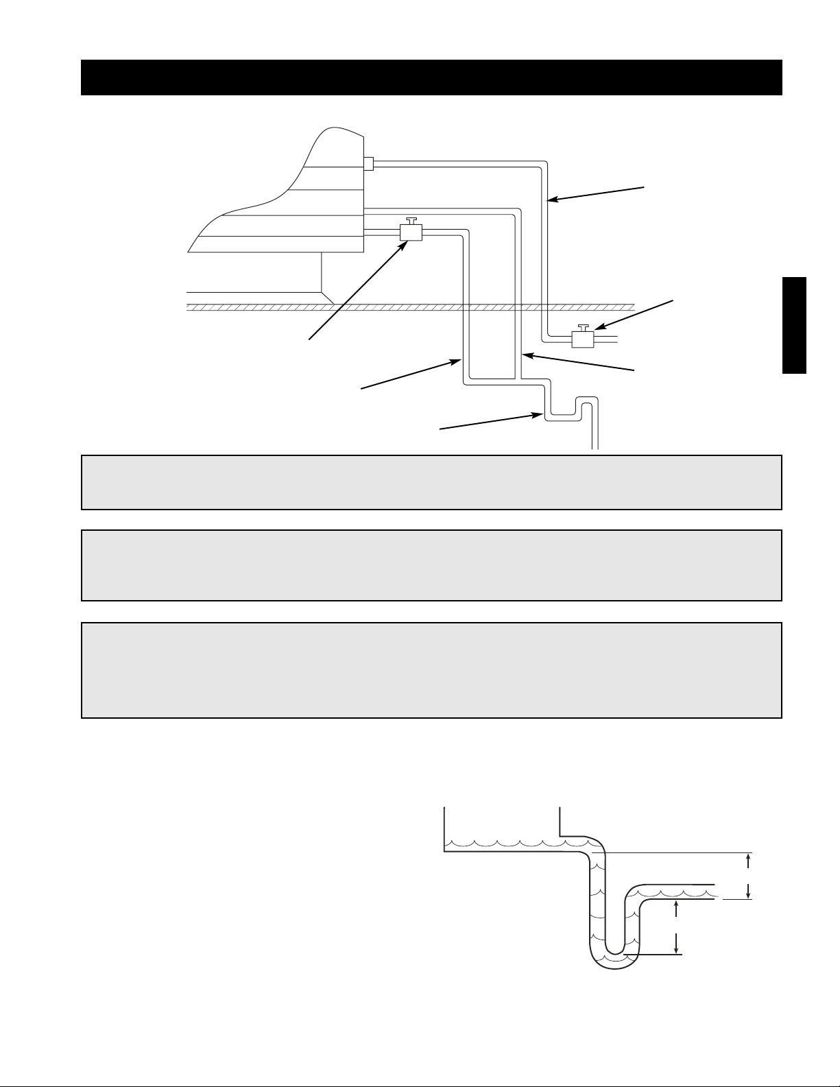
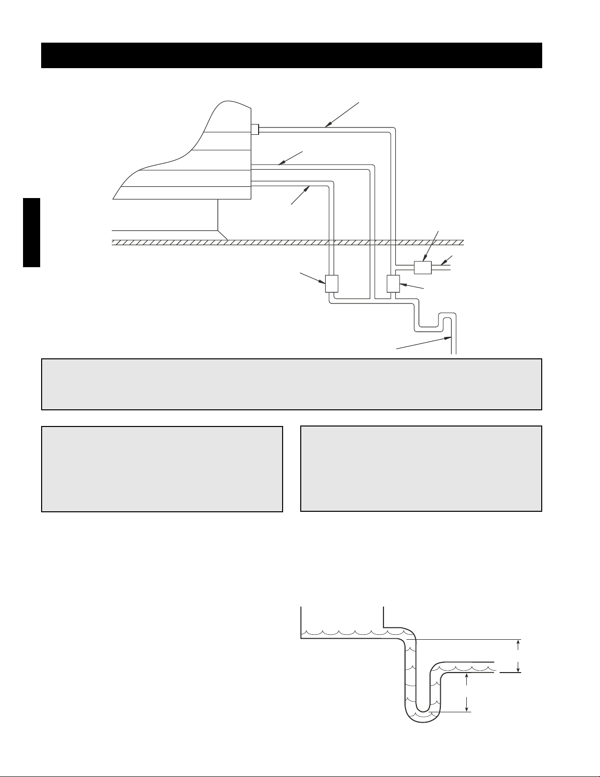
Installation - Evaporative Cooling Piping (Optional)
Evaporative Cooling with Recirculating Pump.
IMPORTANT!
The supply line should be of adequate size and pressure to resupply the amount of water lost due to
bleed-off and evaporation. The drain line should be the same size or larger than the supply line.
Step 1 Install the Water Supply Line
Connect the water supply line to the float valve in the
evaporative cooling unit. Install a manual shutoff
valve in the supply line as shown above.
Step 2 Install the Drain Line
Connect an unobstructed drain line with a manual
shut-off valve from the sump drain to the main drain
line as shown above. Install a drain line from the
sump overflow to the drain line. A trap (as shown to
the right) should be used to prevent sewer gas from
being drawn into the unit.
Step 3 Check/Adjust Water Level
Check the water level in the sump tank. The water
level should be above the pump intake and below the
overflow. Adjust the float as needed to achieve the
proper water level.
CAUTION!
Provisions must be taken to prevent damage to the evaporative cooling section during freezing
conditions. The sump, drain lines and supply lines must be drained prior to freezing conditions or an
alternate method must be used to protect the lines and media.
IMPORTANT!
All solenoids, valves and all traps must be below the roofline or be otherwise protected from freezing.
6 in. min.
6 in. min.
Supply
Line
Overflow
Trap
Drain Line
Valve
Drain
Line
Supply Line
Valve
Page 10
I - 8
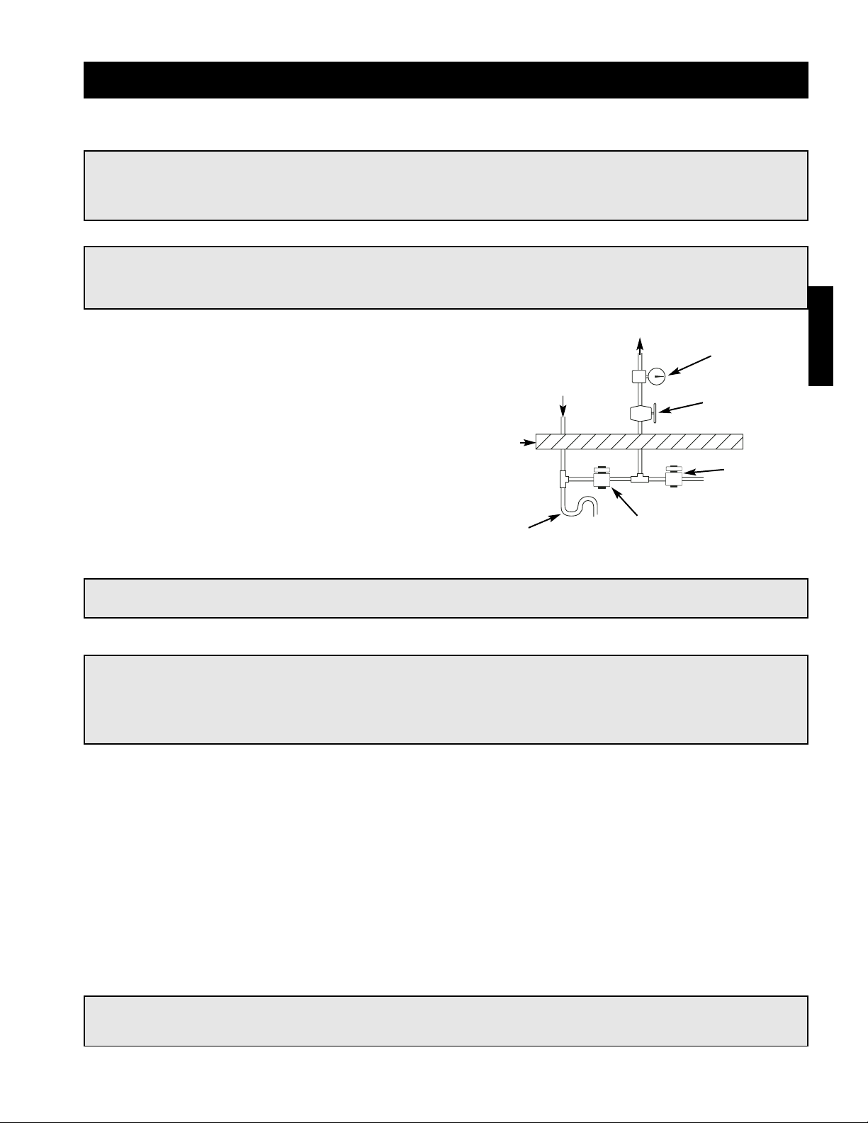
Installation - Evaporative Cooling Piping (Optional)
IMPORTANT!
The supply line should be of adequate size and pressure to resupply the amount of water lost due to
bleed-off and evaporation. The drain line should be the same size or larger than the supply line.
CAUTION!
All solenoids, valves and traps must be installed
below the roof to protect the supply water line
from freezing. If they cannot be installed below
the roof, an alternative method must be used to
protect the lines from freezing
IMPORTANT!
The supply solenoid (Valve A) is NOT the same as
the drain solenoids (Valve B and Valve C). Make
sure to use the proper solenoid for each
location. Check your local code requirements for
proper installation of this type of system.
Step 1 Install the Water Supply Line
Connect the water supply line to the float valve in the unit. Install the 1/2 in. normally closed solenoid (Valve A)
in the supply line as shown above. Install the 1/4 in. normally open solenoid (Valve B) between the supply line
and the drain line as shown above.
Step 2 Install the Drain Line
Connect an unobstructed drain line to the sump drain.
Install the 3/4 in. normally open solenoid (Valve C)
between the sump drain connection and the drain
line. A trap (as shown to the right) should be used to
prevent sewer gas from being drawn into the unit.
Evaporative Cooling with Auto Drain and Fill
g
S
n
S
e
w
Sump
n
e
A
y
B
C
Step 3 Check/Adjust Water Level
Check the water level in the sump tank. The water
level should be above the pump intake and below the
overflow. Adjust the float as needed to achieve the
proper water level.
6 in. min.
6 in. min.
Evaporative Coolin
ectio
Sump Overflo
Drai
upply Lin
Valve
To Water Suppl
Valve
Valve
Drain Lin
Page 11
Evaporative Cooling with the Water Wizard
Installation - Water Wizard (Optional)
Step 3 Wire the Solenoid(s)
Wire the supply solenoid to terminals X and 25 in the control center. Wire the drain solenoid to terminals X and
26 in the control center.
Step 4 Wire the Temperature Sensor
The temperature sensor must be wired. The sensor wire is bundled inside the discharge end of the evaporative
cooler. Wire the sensor wire to terminals AI2 and AIC on the terminal strip in the unit’s control center.
Step 1 Install Supply Line/Solenoid
Connect the water supply line to the manual supply
valve in the unit. Install the supply solenoid in the
supply line, upstream of the manual supply valve and
below the roofline.
Step 2 Install Drain Line/Solenoid
Connect the drain line to the supply line between the
manual supply valve and the supply solenoid. Install a
drain solenoid in the drain line, below the roof line. A
trap (as shown to the right) should be installed in the
drain line.
CAUTION!
Any wiring deviations may result in personal injury or property damage. Greenheck is not responsible
for any damage to, or failure of the unit caused by incorrect final wiring.
NOTE!
The Water Wizard start-up must be completed for proper performance.
NOTE!
Solenoid(s) may be provided by Greenheck (if ordered) or by others.
WARNING!
Disconnect and lock-out all power and gas before performing any maintenance or service to the unit.
Failure to do so could result in serious injury or death and damage to equipment.
Drain Solenoid
Supply
Solenoid
Manual
Supply Valve
Pressure
Gauge
To Media
Sump
Drain
Roof
Line
Trap
NOTE!
The following instructions are provided for evaporative coolers equipped with the Water Wizard only.
I - 9
Page 12
I - 10
Installation - Electrical Wiring
CAUTION!
If replacement wire is required, it must have a temperature rating of at least 105°C, except for energy
cut-off or sensor lead wire which must be rated to 150°C.
CAUTION!
Any wiring deviations may result in personal injury or property damage. Greenheck is not responsible
for any damage to, or failure of the unit caused by incorrect final wiring.
DANGER!
High voltage electrical input is needed for this equipment. This work should be performed by a
qualified electrician.
IMPORTANT!
All wiring should be done in accordance with the latest edition of the National Electric Code
ANSI/NFPA-70 and any local codes that may apply. In Canada, wiring should be done in accordance
with the Canadian Electrical Code.
IMPORTANT!
The equipment must be properly grounded.
Any wiring running through the unit in the airstream must be protected by metal conduit, metal clad
cable or raceways.
Step 1 Determine the Size of the Main
Power Lines
The unit nameplate states the voltage and the unit’s
total amps. The main power lines to the unit should
be sized accordingly.
MODEL
VOLTS
SUP HP
MARK
AMPS
HTZ PH
S/N
EXH HP
Voltage, Hertz,
and Phase
Unit’s Total
Amps
IMPORTANT!
Before connecting power to the unit, read and understand the following instructions and wiring
diagrams. Complete wiring diagrams are attached to the inside of the control center door(s).
IMPORTANT!
Greenheck’s standard control voltage is 24 VAC.
Control wire resistance should not exceed 0.75 ohms (approximately 285 feet total length for 14 gauge
wire; 455 feet total length for 12 gauge wire). If the resistance exceeds 0.75 ohms an industrial-style,
plug-in relay should be wired in place of the remote switch. The relay must be rated for at least
5 amps and have a 24 VAC coil. Failure to comply with these guidelines may cause motor starters to
chatter or not pull in, resulting in contactor failures and/or motor failures.
Page 13

I - 11
Step 4 Wire the Optional Convenience Outlet
The convenience outlet requires a separate 115V power supply circuit. The circuit must include short circuit
protection which may need to be supplied by others.
Step 3 Connect the Main Power
Connect the main power lines to the disconnect switch and main grounding lug(s). Torque field connections to
20 in-lbs. See the control center layout in the reference section for main disconnect and grounding lug(s)
locations.
Installation - Electrical Wiring
Step 2 Provide the Opening(s) for the Electrical Connections
Electrical openings vary by unit size and arrangement and are field supplied.
Step 5 Wire the Accessories
Reference the ladder diagram on the inside of the
control center door for correct wiring of the following
accessories:
NOTE!
TSCP has number-to-number wiring.
NOTE!
Wiring to the Selectrastat, Maxitrol 14
(discharge temperature selector) or 44 (room
override) should be in separate conduit or run
with shielded cable.
• Selectrastat
• Room Override
• Blower Switch
• Heat Switch
• Indicating Lights
• Dirty Filter Indicator
• TSCP
Page 14
I - 12
Step 6 Wire the Optional Evaporative Cooler
Reference the ladder diagram on the inside of the control center door for correct wiring of the optional pump
and the optional auto-drain and flush. Wiring instructions for the optional Water Wizard are included in the Water
Wizard installation instructions.
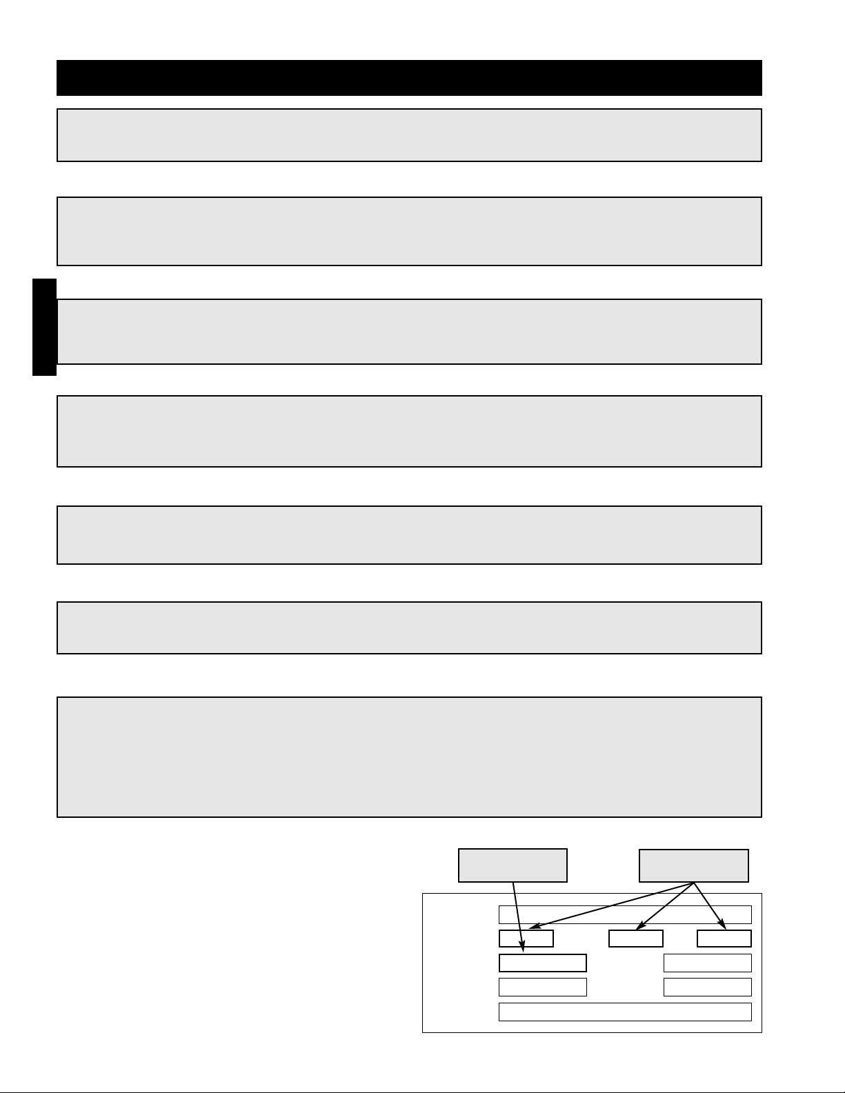
Step 7 Check Recirculation / VAV
Operation
Two Position Damper Control
Turn the recirculating switch on the remote control
panel to each position and confirm that the return air
damper adjusts accordingly. The damper actuator
may take a few minutes to open or close.
Two Speed
Turn the fan speed switch on the remote control
panel to each position and confirm that the fan speed
adjusts accordingly
Potentiometer Control
To test potentiometer operation, turn the
potentiometer to the two extremes. With 80/20
recirculation, confirm that the return air damper fully
opens and fully closes. The damper actuator may
take a few minutes to open or close. With variable
volume, make sure the fan goes to maximum and
minimum speed.
Building Pressure Control
See I-15 for building pressure set-up and operation
check.
NOTE!
Large evaporative coolers may require a separate power supply.
Installation - Electrical Wiring
NOTE!
For maintenance issues associated with variable
frequency drives, consult the drive’s manual
supplied with the unit. The drives are
programmed at the factory and should not need
any adjustment during installation and start-up.
For kitchen applications, the drive may be
located in the kitchen or in the unit.
NOTE!
Blower start-up (S-1), steps 1-4 should be
performed before the blower is run.
70
65
75
80
85
90
60
55
(OPTIONAL)
BLOWER
DIRTY FILTERS
MAIN VALVES
ALARM
EXHAUST
SUPPLY
HEAT
(OPTIONAL)
GREENHECK
®
PHOTOHELIC
70
65
75
80
85
90
60
55
(OPTIONAL
)
BLOWE
R
DIRTY FILTERS
MAIN VALVES
ALARM
EXHAUST
SUPPLY
HEA
T
(OPTIONAL
)
GREENHE
CK
®
70
65
75
80
85
90
60
55
GREENHECK
®
(OPTIONAL)
BLOWER
DIRTY FILTERS
MAIN VALVES
ALARM
RECIRCULATION
EXHAUST
SUPPLY
HEAT
(OPTIONAL)
2-Position Damper Control
Building Pressure Control
Potentiometer Control
Page 15
I - 13
Installation - Direct Gas Piping
Step 1 Determine the Supply Gas Requirements
The unit’s direct gas nameplate states the requirements for the gas being supplied to the unit.
IMPORTANT!
All gas piping must be installed in accordance with the latest edition of the National Fuel Gas Code
ANSI/Z223.1 and any local codes that may apply. In Canada, the equipment shall be installed in
accordance with the Installation Code for Gas Burning Appliances and Equipment (CGA B149) and
Provincial Regulations for the class. Authorities having jurisdiction should be consulted before
installations are made.
WARNING!
All components of this or any other gas-fired heating unit must be leak tested prior to placing the unit
into operation. A soap and water solution should be used to perform this test. NEVER test for gas
leaks with an open flame.
WARNING!
If pressure testing in excess of 1/2 psig
(3.5 kPa), the heater and manual shutoff valve
must be disconnected from the supply gas line.
WARNING!
If pressure testing at or below 1/2 psig (3.5 kPa),
the heater must be isolated from the supply gas
line by closing its manual shutoff valve.
IMPORTANT!
All piping should be clean and free of any foreign
matter. Foreign material entering the gas train
can damage the valves, regulators and burner.
“W.C.
“W.C.
“W.C.
F
PSI
“W.C.
“W.C.
MAX BTU/HR
BTU/H MAX
NORMAL MANIFOLD
PRESSURE
PRESSION D’ADMISSION
NORMALE
MIN GAS
PRESSURE
PRESSION DE GAZ
MIN BURNER
PRESSURE DROP
PERTE MIN DE PRESSION
DANS LE BRULEUR
TYPE OF GAS
NATURE DU GAZ
MIN BTU/HR
BTU/H MIN
MIN GAS PRESSURE
FOR MAX OUTPUT
PRESSION DE GAZ MIN
POUR PUISSANCE MAX
MAX BURNER
PRESSURE DROP
PERTE MAX DE PRESSION
DANS LE BRULEUR
MAX GAS
PRESSURE
PRESSION DE GAZ
MAX
DESIGN ∆T
∆T NORMALE
EQUIPPED FOR
CONCU POUR
SCFM
“W.C.
EXTERNAL STATIC PRESSURE
PRESSION STATIQUE EXTERIEURE
AGAINST
CONTE
Minimum and
maximum gas
pressures
Minimum gas
pressure for
maximum output
Type of Gas
IMPORTANT!
Do NOT connect the unit to gas types other than
what is specified and do NOT connect the unit
to gas pressures that are outside of the pressure
range shown on the label.
Page 16

I - 14
Installation - Direct Gas Piping
From
Gas
Supply
Gas Cock
1/8 in. Plugged Tap
6 in. Trap
Ground Joint Union
Step 3 Connect the Supply Gas Line
A manual shut off valve (gas cock), 1/8 in. plugged
test port and 6 in. drip leg must be installed prior to
the gas train. The valve and test port must be
accessible for the connection of a test gauge. Supply
gas connections must be made by a qualified installer
and are not furnished by Greenheck.
Step 2 Install Additional Regulator if
Required
If the supply gas pressure exceeds the maximum gas
pressure shown on the direct gas nameplate, an
additional regulator (by others) is required to reduce
the pressure. The regulator must have a listed leak
limiting device or it must be vented to the outdoors.
Step 4 Pipe the Optional Vent Line
If an optional vent line is located between the safety
shutoff valves it must be piped to the outdoors.
Step 5 Test the System for Leaks
Check both the supply lines and the factory piping for
leaks. Apply a soap and water solution to all piping
and watch for bubbling which indicates a leak.
WARNING!
The factory piping has been checked for leaks, but should be rechecked due to shipping and
installation.
WARNING!
NEVER test for a gas leak with an open flame.
NOTE!
The regulator located inside the unit is used to
adjust the unit’s maximum output temperature.
NOTE!
Reference the National Fuel Gas Code for
additional vent line requirements.
Safety Shut-off
Valve
Safety Shut-off
Valve
Vent Line
Solenoid
To Burner
Vent Line
To Outdoors
From Supply
Make-Up Air
Unit
Page 17

Step 1 Mount Pressure Tap
Using the factory provided bracket, mount the
pressure tap to the outside of the unit. Choose a
location out of the prevailing winds and away from
supply or exhaust fans to assure accurate readings.
Step 2 Run Pressure Tap Lines
A pressure tap line must be run from the pressure tap
mounted on the outside of the unit to the low
pressure tap on the back of the photohelic gauge. A
second pressure tap line must be run from the high
pressure tap on the back of the photohelic to the
space. Fifty feet of tubing is supplied with the unit.
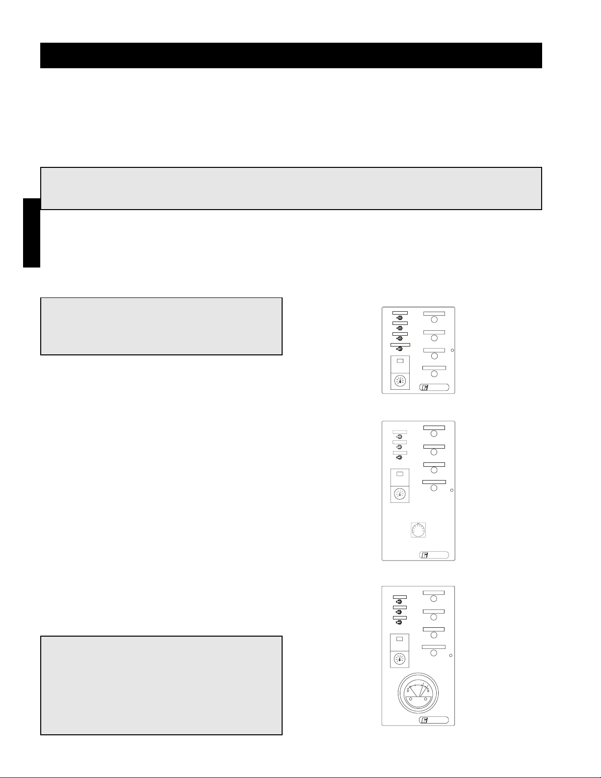
Step 3 Set the Building Pressure
The pressure gauge (pictured bottom right) is used to
set the desired building pressure. The pressure is set
by adjusting the knobs for the upper and lower
pressure limits. Typical settings are 0.0 in. wc for the
lower and 0.10 in. wc for the upper pressure setting.
Step 4 Check Control System
Before the unit is left in service, the recirculation
control system should be tested. This can be
accomplished by turning both knobs to the upper
most pressure setting. You may have to remove the
outdoor pressure tap tubing. The return air damper
should close (VAV systems should go to max speed).
Then set both knobs at the lowest setting, and the
damper should open (VAV systems should go to
minimum speed). It may take one to two minutes for
the damper to reach the desired position.
Reset the correct pressure limits before starting the
unit.
The picture on the bottom right shows a typical
photohelic setting. The needle in this photo indicates
a negative building pressure. During correct operation
the indicating needle will remain between or near the
setting needles.
Installation - Building Pressure Control (Optional)
Low
Pressure Tap
To Outside
Factory
Wiring
High
Pressure
Tap To
Space
Pressure Setting Knobs
Pressure Setting
Needles
Pressure Indicating
Needle
I - 15
NOTE!
Blower start-up (S-1), steps 1-4 should be
performed before the blower is run.
Page 18

Start-Up - Blower
MODEL
VOLTS
SUP HP
MARK
AMPS
Hz PH
S/N
EXH HP
Voltage, Hertz,
and Phase
Step 1 Check the Voltage
Before starting the unit, compare the supplied voltage, hertz, and phase with the unit and motor’s nameplate
information.
Step 2 Check the Blower Rotation
Open the blower access door and run the blower momentarily to determine the rotation. Arrows are placed on
the blower scroll to indicate the proper direction or reference the example below.
IMPORTANT!
If the blower is rotating in
the wrong direction, the
unit will move some air,
but will not perform as
designed. Be sure to
perform a visual inspection
to guarantee the correct
blower rotation.
SPECIAL EQUIPMENT REQUIRED
Below is a list of special tools that are required. A recommended model is shown, but equivalent
products may be used.
Description
Manufacturer-Model Phone Website
Voltage Meter Fluke-23 1-800-44-FLUKE www.fluke.com
Amperage Meter Fluke-23 1-800-44-FLUKE www.fluke.com
Thermometer Fluke-50 1-800-44-FLUKE www.fluke.com
U-Tube manometer Dwyer-Slack Tube 1-219-897-8000 www.dwyer-inst.com
Tachometer Monarch-Pocket Tach 100 1-800-999-3390 www.monarchinstruments.com
WARNING!
Disconnect and lock-out all power and gas before
performing any maintenance or service to the
unit. Failure to do so could result in serious injury
or death and damage to equipment.
NOTE!
To reverse the rotation on three phase
units, disconnect and lock-out the power,
then interchange any two power leads.
NOTE!
To reverse the rotation on single phase
units, disconnect and lock-out the power,
then rewire the motor per the
manufacturer’s instructions.
WARNING!
Check the housing, evaporative cooler, blower, weatherhood, filter section and ductwork for foreign
objects and debris before the blower is run.
Pre-Start-Up Check
Rotate the fan wheel by hand and make sure no parts
are rubbing. Check the V-belt drive for proper
alignment and tension (a guide for proper belt tension
and alignment is provided in the belt maintenance
section). Check fasteners, set screws and locking
collars on the fan, bearings, drive, motor base and
accessories for tightness. Remove any shipping
fasteners from the blower vibration isolators.
S - 1
Rotation
Blower
Housing
Page 19

Start-Up - Blower
Step 5 Air Volume Measurement and
Check
Measure the unit’s air volume (CFM) and compare it
with its rated air volume. If the air volume is off, adjust
the fan RPM by changing the drive.
Step 6 Set-up Optional Components
Adjust the settings on the optional components. See the control center layout in the reference section for
location of optional components.
• Heating Inlet Air Sensor (typical setting: 60-70ºF)
• Cooling Inlet Air Sensor (typical setting: 75ºF)
• Building Freeze Protection (typical setting: 5 min at 45ºF)
• Dirty Filter Gauge (typical setting: settings vary greatly for each unit)
• Solid Fuel Time Delay (typical setting varies per application)
NOTE!
The most accurate way to measure the air
volume is by using a pilot traverse method
downstream of the blower. Other methods can
be used but should be proven and accurate.
IMPORTANT!
Changing the air volume can significantly increase the motor’s amps. If the air volume is changed, the
motor amps must be checked to prevent overloading the motor.
Step 3 Check for Vibration
Check for unusual noise, vibration or overheating of the bearings. Reference the troubleshooting section for
corrective actions.
IMPORTANT!
Excessive vibration may be experienced during
the initial start-up. Left unchecked, it can cause
a multitude of problems including structural
and/or component failure.
IMPORTANT!
Generally, fan vibration and noise is transmitted
to other parts of the building by the ductwork.
To minimize this undesirable effect, the use of
heavy canvas duct connectors is recommended.
Step 4 Motor Check
Measure the motor voltage, amps and RPM and compare to the specifications on the motor nameplate. Check
the overload setting and make sure it matches the motor’s amperage rating. If the motor’s actual amps are
greater than the nameplate amps, check and correct the supply voltage or air volume of the blower.
NOTE!
Additional starters and overloads may be provided in the make-up air control center for optional
exhaust blowers. Any additional starters and overloads must also be checked for proper voltage, amps
and RPM’s.
S - 2
Page 20

Step 1 Check the Supply Gas Pressure
Check the supply gas pressure and compare it with the unit’s nameplate pressure requirements. Adjust the
supply regulator as needed until the supply gas pressure is within the specified range.
S - 3
IMPORTANT!
For proper unit function and safety, follow the
start-up procedure in the exact order that it is
presented.
“W.C.
“W.C.
“W.C.
F
PSI
“W.C.
“W.C.
MAX BTU/HR
BTU/H MAX
NORMAL MANIFOLD
PRESSURE
PRESSION D’ADMISSION
NORMALE
MIN GAS
PRESSURE
PRESSION DE GAZ
MIN BURNER
PRESSURE DROP
PERTE MIN DE PRESSION
DANS LE BRULEUR
TYPE OF GAS
NATURE DU GAZ
MIN BTU/HR
BTU/H MIN
MIN GAS PRESSURE
FOR MAX OUTPUT
PRESSION DE GAZ MIN
POUR PUISSANCE MAX
MAX BURNER
PRESSURE DROP
PERTE MAX DE PRESSION
DANS LE BRULEUR
MAX GAS
PRESSURE
PRESSION DE GAZ
MAX
DESIGN ∆T
∆T NORMALE
EQUIPPED FOR
CONCU POUR
SCFM
“W.C.
EXTERNAL STATIC PRESSURE
PRESSION STATIQUE EXTERIEURE
AGAINST
CONTE
Minimum and
maximum gas
pressures
IMPORTANT!
This start-up should begin after all of the
installation procedures and the blower start-up
have been completed.
Start-Up - Direct Gas
Step 2 Check the Pilot Gas Pressure
Check the pilot gas pressure. The recommended gas pressure is 3 in. wc. Adjust the pilot regulator as needed.
See the gas train layout in the reference section for the location of the pilot pressure test port and pilot regulator.
Step 2 Check the Optional High and Low Gas Pressure Switches
Check the settings on the high and low gas pressure switches. The high pressure setting is typically 8 in. wc
and the low pressure is setting is typically 3 in. wc. The switches are set at the factory and should not need
adjustment. Adjust the setting only if needed. See the gas train layout diagram in the reference section for the
high and low pressure switch location.
NOTE!
The purpose of the high and low gas pressure switches is to automatically shut down the burner if the
inlet gas pressure is too low for the burner to safely light or if the manifold pressure is to high for the
burner to operate properly.
Page 21

7
6
0.625 - 0.675 in. W.C.
Start-Up - Direct Gas
S - 4
Step 4 Set the Burner Air Pressure
Differential
With the fan running and discharging 70°F air,
connect a U-Tube manometer to the outer sensing
probes (see below) and measure the static pressure
across the burner.
The static pressure MUST be between 0.625 and
0.675 inches wc. Evenly adjust the baffles above and
below the burner, keeping the burner centered in the
opening until the required pressure is obtained.
Outer Sensing Probes
IMPORTANT!
Proper air velocity over the burner is critical on direct fired gas units. If the air velocity is not within
the unit specifications, the unit will not operate efficiently, may have sporadic shutdowns and may
produce excessive carbon monoxide (CO) or other gases.
NOTE!
To increase the static pressure decrease the
opening. To decrease the static pressure
increase the opening.
IMPORTANT!
This process may need to be repeated until the
proper pressure is achieved. This adjustment will
change the air quantity delivered by the unit and
therefore the air quantity delivered should be
rechecked. Refer to the blower start-up section.
NOTE!
When required pressure is obtained be sure to
reconnect the outer sensing probes.
Adjustable
Top Baffle
Air Flow
Burner
Adjustable
Bottom Baffle
Page 22

Remove the wire
from terminal #4
to send the unit
to maximum fire
Start-Up - Direct Gas
Maxitrol Series 14
(7 terminals)
S - 5
Low fire time delay
setting
(75% of maximum)
Remove the
wire from the #3
terminal to send
the unit to
maximum fire
Maximum discharge
temperature setting
(100°F Typical)
Minimum
discharge
temperature
setting
(50°F Typical)
Low fire time delay
setting
(75% of maximum)
Maxitrol Series 44
(9 terminals)
Step 6 Set the Maximum Firing Rate
Monitor the unit’s actual temperature rise by placing a
thermocouple in the unit’s inlet and a second in the
discharge, three duct diameters downstream of the
burner.
Send the unit to high fire by disconnecting and
isolating the proper wire on the Maxitrol amplifier.
(Terminal #4 for Maxitrol 14, #3 for Maxitrol 44 as
shown below).
Continues on next page...
Step 5 Set the Low Fire Time Delay
Set the low fire time delay to 75% of its maximum
setting. See the drawings below for the location of
the time delay setting.
WARNING!
Do not set the burner maximum firing rate based
on gas pressure. It should be set based on the
unit’s designed temperature rise shown on the
direct gas label.
“W.C.
F
PSI
MAX BTU/HR
BTU/H MAX
NORMAL MANIFOLD
PRESSURE
PRESSION D’ADMISSION
NORMALE
MIN GAS
PRESSURE
PRESSION DE GAZ
MIN BURNER
PRESSURE DROP
PERTE MIN DE PRESSION
DANS LE BRULEUR
TYPE OF GAS
NATURE DU GAZ
MIN BTU/HR
BTU/H MIN
MIN GAS PRESSURE
FOR MAX OUTPUT
PRESSION DE GAZ MIN
POUR PUISSANCE MAX
MAX BURNER
PRESSURE DROP
PERTE MAX DE PRESSION
DANS LE BRULEUR
MAX GAS
PRESSURE
PRESSION DE GAZ
MAX
DESIGN ∆T
∆T NORMALE
EQUIPPED FOR
CONCU POUR
SCFM
“W.C.
EXTERNAL STATIC PRESSURE
PRESSION STATIQUE EXTERIEURE
AGAINST
CONTE
Page 23

Step 6 Set the Maximum Firing Rate (...continued)
While monitoring the units temperature rise, set the maximum firing rate by adjusting the regulator (as shown
below) until the desired temperature rise is achieved. After setting the maximum firing rate, reconnect the wire
to the amplifier.
IMPORTANT!
Setting the maximum firing rate during mild weather conditions may cause the high limit to trip out
during extreme conditions requiring manual resetting.
NOTE!
Gas trains are equipped with either separate
regulators and modulating valves or with a
combined modulating regulator.
NOTE!
Clockwise rotation increases the temperature rise, counterclockwise rotation decreases the
temperature rise.
Remove cap to access
maximum firing rate
adjustment
Separate Regulator and
Modulating Valve
Combined Modulating
Regulator
Maximum firing rate
adjustment
Start-Up - Direct Gas
S - 6
NOTE!
The minimum setting for the maximum firing rate
may be higher than required. This is acceptable,
the burner will modulate as needed.
Page 24

Start-Up - Direct Gas
Step 7 Set the Minimum Firing Rate
Disconnect and isolate one of the wires running to the
modulating valve to send the unit to its minimum
firing rate. Set the minimum firing rate by adjusting
the needle valve as shown in the figures below.
After setting the minimum firing rate, shut off the pilot
to ensure that the flame safe guard can still read the
main flame signal. Reconnect the wire to the
modulating valve and open the pilot shut-off valve.
Remove one wire to
send the unit to the
minimum firing rate.
NOTE!
Gas trains are equipped with either separate regulators and modulating valves or with a combined
modulating regulator.
NOTE!
On units with a 42 inch or greater burner, the flame safe guard will automatically shut off the pilot
after the burner has been ignited.
IMPORTANT!
The proper setting for the minimum firing rate
results in a small ribbon of continuous flame
across the entire burner.
IMPORTANT!
Do not allow the disconnected wire to come in
contact with a potential ground, damage to the
amplifier or transformer could result.
S - 7
NOTE!
Adjusting the maximum and minimum firing rate requires the inlet air sensor to be set higher than the
outside air temperature to start the burner(s). Once high and low fire have been set, the inlet air
sensor should be set to the desired temperature.
NOTE!
Counterclockwise rotation increases the
minimum fire rate setting, clockwise rotation
decreases the setting.
Separate Regulator and
Modulating Valve
Combined Modulating
Regulator
Minimum firing rate
adjustment
Minimum
firing rate
adjustment
Remove one wire to
send the unit to the
minimum firing rate.
Page 25

Step 9 Flame Signal Check
To measure the flame signal connect a standard DC
voltmeter to the flame amplifier test jacks + and (com) as shown to the right. The flame signal should
be above 1.25 VDC and steady.
Check the flame signal with the burner at pilot only,
minimum fire, mid-fire and high-fire.
NOTE!
If the fame signal is not above 1.25 VDC and
steady, consult the troubleshooting section.
Start-Up - Direct Gas
Step 8 Set the Unit’s Operating Temperature
Set the operating temperature. The operating temperature setting depends on which Maxitrol controller is used
and the desired space temperature.
Maxitrol Series 14
(Discharge temperature control)
Set the discharge
temperature
(65°F Typical)
IMPORTANT!
The Maxitrol Series 14 should be set to the
desired discharge temperature. The
temperature selector may be built into the
amplifier or may be a stand-alone dial. The
stand-alone dial may be mounted remotely.
Maxitrol Series 44
(Space temperature control)
IMPORTANT!
The Maxitrol Series 44 should be set to the
desired room temperature. The Selectrastat
must be mounted in the space.
Set the space
temperature
(70°F Typical)
S - 8
Page 26

S - 9
Start-Up - Evaporative Cooling (Optional)
Step 1 Check the Installation
The media may have been removed during installation, so its
orientation should be double checked. The media should be
installed with the steeper flute angle sloping down toward the
entering air side. See the figure on the right.
Verify that the stainless steel caps and distribution headers
are in place. The headers should be located over the media
towards the entering air side. The caps should be placed over
the headers.
Leaving Air
Entering Air
45°
15°
Step 2 Check the Pump Filter
Check that the pump filter is around the pump inlet.
Step 3 Fill the Sump and Adjust the
Float
Turn on the water supply and allow the pan to fill.
Adjust the float valve to shut-off the water supply
when the sump is filled to within 1 in. of the bottom of
the overflow.
Overflow
Pump
Filter
Threaded Float
Adjustment
Float
Valve
Step 4 Break-in the Media
Open the bleed-off valve completely and saturate the media with the blower(s) off for no less than 20 minutes. A
jumper will need to be installed in the control center to power the evaporative pumps with the blower(s) off.
Reference the unit’s ladder diagram to determine proper terminals.
Page 27

Step 6 Adjust the Water Bleed-Off Rate
The water bleed-off rate is dependent on the water’s
mineral content. The bleed-off should be adjusted
based on media’s mineral deposits after two weeks of
service.
Step 8 Put the Unit into Service
Remove the jumper, and energize the blower(s). Verify proper operation.
Start-Up - Evaporative Cooling (Optional)
Step 5 Check the Flow Rate
The pumps should provide enough water to saturate the media in 45 to 60 seconds. Consult the factory, if
adequate flow is not achieved.
Bleed-Off Valve
Step 7 Set the Optional Auto Drain and
Fill
Set the auto drain and fill timer and temperature
settings. Timer settings are t1: 1.0, 10min and t2: 0.4,
60h Temperature is typically set to 45ºF.
IMPORTANT!
Check the media for minerals after two weeks of service and adjust the bleed-off rate accordingly.
Evaporative
Timer
t2 settings
t1 settings
Evaporative
Freeze Protection
Temperature
Setting
S - 10
Page 28

Start-Up - Water Wizard (Optional)
NOTE!
The manual supply valve ships closed and must be adjusted for proper performance.
NOTE!
Three sided evaporative coolers have two manual supply valves. Each valve has a different pressure
setting which must be set.
WARNING!
Opening the manual supply valve will allow water to pass to the media. Be sure the sump is safely
draining before opening the manual supply valve.
Step 2 Set the Water Pressure
With the solenoid open, set the supply water pressure to the correct setting from the following tables. Use the
manual supply valve to adjust the supply pressure. A pressure gauge is provided between the manual supply
valve and the media.
Step 3 Break-in Media
Leave the supply solenoid open to saturate and break-in the media for 20 minutes with the blowers off.
Step 1 Open the Solenoid
Confirm that the manual water supply valve is closed.
Press and hold the function button for one second. L3
will begin blinking (short on, long off), indicating that
flow test mode is active and the supply solenoid is
open.
One Sided Evaporative Coolers
Housing Water Pressure (in. w.c.)
H 40 51
Three Sided Evaporative Coolers
Housing
Water Pressure (in. w.c.)
Front Sides
H 40 30 21
H 50 21 26
Function
Key
L1 L2 L3
Enter
Key
Up
Key
Down
Key
S - 11
Page 29

NOTE!
Steps 6-8 are provided to adjust the minimum cooling temperature. The minimum cooling temperature
is preset to the factory recommended 75ºF. Only adjust if needed.
NOTE!
The inlet air sensor function overrides and shuts down the evaporative cooler if the outside
temperature falls below the minimum cooling temperature.
Step 6 Enter Program Mode
Press and hold the enter key for three seconds. The display
will read “Pro” when program mode is active.
Start-Up - Water Wizard (Optional)
Step 4 Close Solenoid
With the pressure set, press the function key for one second to deactivate flow test mode and allow the supply
solenoid to close.
Step 5 Check Media
Start the cooling cycle and check the media after one hour of operation. If the media is continuously dry or if too
much water is draining from the sump tank, refer to Water Wizard troubleshooting.
S - 12
Step 7 Adjust the Minimum Cooling
Temperature
While in the program menu, use the up and down keys to
navigate the menu options until “toF” is displayed. Press the
enter key to access the selected menu option setting. Use the
up and down keys to adjust the minimum cooling
temperature as needed. Press the enter key to save the new
minimum cooling temperature setting and return to the
program menu.
IMPORTANT!
The enter key must be pressed to save the new minimum cooling temperature.
Page 30

Step 9 Enter Program Mode
Press and hold the enter key for three seconds. The display
will read “Pro” when program mode is active.
Step 10 Adjust the Freeze Temperature
While in program mode, use the up and down keys to
navigate through the menu options until “Frt” is displayed.
Press the enter key to access the selected menu option
setting. Use the up and down keys to adjust the freeze
temperature setting as needed. Press the enter key to set the
freeze temperature and return to the program menu.
Step 11 Exit Program Mode
After ten seconds of idle time the controller will exit program mode.
Step 8 Exit Program Mode
After ten seconds of idle time the controller will exit program mode.
NOTE!
The freeze temperature is the temperature at which the supply solenoid closes and the drain solenoid
opens to drain the supply line, preventing possible freeze damage.
NOTE!
Steps 9-11 are provided to adjust the freeze temperature setting. The freeze temperature is preset to
the factory recommended 45ºF. Only adjust if needed.
IMPORTANT!
The enter key must be pressed to save the new freeze temperature.
Start-Up - Water Wizard (Optional)
S - 13
Page 31

Operation - Recirculating / VAV Units
Manual Quadrant Damper Control
A manual quadrant damper in the return airflow controls the amount of recirculated air. This damper can be
adjusted by hand and locked in position for either 100% outside air or maximum recirculation air.
2-Position Damper Control
A 2-position spring return actuator is used to control the return air amounts. The damper moves from open to
closed. If power is cut to the unit, the damper will fail close. The volume of recirculation air is set in the factory
by baffles in the return air opening. These baffles should not be removed or adjusted in the field.
Potentiometer Control
A modulating spring return actuator is used to control the return air amounts. The damper moves from fully open
to fully closed. The amount of return air is determined by the position of a remote potentiometer.
Building Pressure Control
A modulating spring return actuator is used to control the return air amounts according to input from a pressure
sensing device. The recirculation damper moves from fully open to fully closed.
2-Speed Control
A 2-speed motor is used to control air volumes. The motor can be switched to low or high speed from a remote
control panel. One-half or one-third reduction motors are used.
Potentiometer Control
A variable frequency drive is controlled by input from a remote speed selector (potentiometer). This unit allows
easy manual adjustment of make-up air volumes.
Building Pressure Control
A variable frequency drive is controlled according to input from a pressure sensing device.
Variable Frequency Drives
For maintenance issues associated with the variable frequency drives, please consult the drive’s manual
supplied with the unit. The drives are programmed in the factory and should not need any adjustment during
installation and start-up. For kitchen applications, the drive is typically located in the kitchen, not in the unit.
The self-adjusting burner bypass damper is a device used in variable volume and recirculation units. Its function
is to maintain proper combustion by providing a constant airflow over the burner when outside air volumes are
changed. It is located underneath the burner as shown in the picture below.
Burner Bypass Damper
80/20 Operation (Optional)
Variable Volume Operation (Optional)
Burner
Bypass
Damper
WARNING!
The burner bypass damper is set-up at the
factory. The weights and springs should not be
adjusted in the field. The damper may not fully
close during minimum outside air mode.
O - 1
Page 32

Operation - Electrical
1. Exhaust Fan Switch (S1) Closed
• Power passes to exhaust starter(s) ST2(3)
• N.O. exhaust starter switches are energized
and closed
• Power passes to exhaust fans
• Exhaust fans start
2. Supply Fan Switch (S2) Closed
• N.O. contact(s) ST2(3) are closed
• Power passes to optional freeze protection
relay (FZ1) and if temperature is acceptable
N.C. contact (FZ1) remains closed
• Power passes to damper which opens
• When damper is fully opened, damper relay
(D1) is energized and N.O. damper limit switch
(DL1) closes.
• Power passes to and energizes supply starter
relay (ST1)
• Supply starter contact (ST1) closes and power
reaches and energizes supply fan
• Supply fan starts
4. Evaporative Cooling Switch (S4)
Closed*
• N.O. contact ST1(AUX) is energized and closed
• Power passes to and energizes cool relay (R1)
• N.O. contact R1 is energized and closed
• Power passes to evaporative cooling pump (P1)
*If DX or chilled water coils are used rather than
an evaporative cooler, the cooling sequence of
operation will depend on the coil controls.
Cooling coil controls are supplied by others.
3. Heat Switch (S3) Closed
• Power passes to N.O. ST1 which is energized
and closed
• Power passes to inlet air sensor contact (TS1)
which is energized and closed if proper inlet air
temperature is present
• Power passes to and energizes heat relay (R2)
• N.O. heat relay contact (R2) closes
• Power passes to and energizes terminal 5 of
the Flame Safe Guard (FSG)
• Power passes to N.C. high limit control contact
(HLC1) which is closed if the temperature
remains below the set point
• Power passes to N.O. and N.C. gas pressure
contacts (PS1) which are both closed if gas
pressure is within the set range
• Power passes to terminal 6 of the FSG
• FSG begins direct gas burner sequence (see
direct gas sequence)
1. Supply Fan Switch Closed
• Power passes to the supply fan and heat switch
2. Heat Switch Closed
• Power passes to the heat relay then to the
Flame Safe Guard
3. Flame Safe Guard (FSG) Sequence
• Checks for proper airflow
• Verifies no flame present at burner
• Initiates 10 second prepurge
• Sends power to open pilot valve (V1) and
energizes the spark generator (SG1) (clicking of
the spark generator may be heard).
• Tries for up to 10 seconds to light pilot and
confirm flame.
• Powers the main gas valves (V2 and V3) open
• Shuts down spark generator
• Continuously monitors the flame and airflow
• Performs self-diagnostic check every five
seconds
Electrical Sequence Direct Gas Burner Sequence
O - 2
Page 33

Operation - Water Wizard
Key Functions
Function Key
L1 L2 L3
Enter Key
Up Key
Down Key
Flow Test Mode
Activating flow test mode opens the supply solenoid and allows water to pass to the manual supply valve. To
activate flow test mode, press and hold the function key for one second (L3 will flash). To deactivate flow test
mode and allow the supply solenoid to close, press and hold the function key again for one second.
Program Mode
Program mode allows the user to view the program menu and edit the factory default settings. To access
program mode and view the program menu press and hold the enter key for three seconds. While viewing the
program menu press the up and down keys to scroll through the menu options. To view the setting of the
selected menu option press the enter key. To edit the setting, press the up or down key while viewing the
setting. To save the setting and return to the program menu press the enter key. To return to the program menu
without saving the change, wait 10 seconds. To exit program mode from the program menu, wait 10 seconds.
Drain Mode
Drain mode locks open the drain solenoid and drains the supply line between the supply solenoid and the
media. To activate drain mode simultaneously press the function and enter keys (L2 will light). To deactivate
drain mode and unlock the drain solenoid, simultaneously press the function and enter keys again.
Dry Bulb Temperature
The default display is the dry bulb temperature of the
outside air.
Wet Bulb Temperature
To view the wet bulb temperature, simultaneously
press and hold the up and down keys.
CAUTION!
The sump drain line must be clear and draining
to a safe location before using flow test mode.
NOTE!
The enter key must be pressed to save any
changes made to a setting.
WARNING!
Changing the default settings will significantly
affect performance. Only change a setting after
reading and understanding this entire manual.
CAUTION!
Be aware of the water level in the sump tank at
all times when using the flow test mode.
Indicating Lights
Three indicating lights are located across the top of the display to indicate the status of the Water Wizard.
Light Status
On Off
Blinking Blinking
(Long on, short off) (Short on, long off)
L1 Call For Cooling
No Call For
N/A N/A
Cooling
L2
Drain Solenoid Drain Solenoid
N/A N/A
Open Closed
L3 Cooling On Cooling Off
Supply Solenoid Flow Test Mode
Locked Closed Active
O - 3
Page 34

Troubleshooting
115 Vac across
terminals 102 and 101?
Check Main Voltage
(See Blower Start-Up Step #1)
Main Disconnect (DS1) Off
(Turn Main Disconnect DS1 On)
Primary Fuses (FU6) or Secondary Fuses (FU7) Blown
(Replace Fuses)
Main Transformer (TR1) Defective
(Replace Transformer TR1)
24 Vac across
terminals R and X?
Secondary Fuse (FU8) Blown
(Replace Fuses)
Main Transformer (TR1) Defective
(Replace Transformer)
24 Vac across
terminals 8 and X?
Supply Fan Overload (ST1 OL) Tripped
(Reset and check motor amps, reference blower start-up #4)
24 Vac across
terminals 7 and X?
Damper Limit Switch (DL1) Holding
(Wait for actuator to open fully or adjust limit switch)
Damper Limit Switch Jumper Missing
(Install jumper, reference the unit ladder diagram for terminals)
24 Vac across
terminals 6 and X?
Optional Exhaust Fan Interlocks (ST2-ST5) Open
(Correct/Replace)
Freeze Protection (FZ1) Tripped
(Reset)
24 Vac across
terminals G and X?
Supply Switch (S2) Off
(Turn Supply Switch S2 On)
Fire System Contact (FSC) Tripped
(Correct/Replace)
No
No
No
No
No
No
Yes
Yes
Yes
Yes
Yes
Note: At this time the supply contactor (ST1) should pull in passing
power to the supply motor and the blower should start.
Yes
Blower Does Not Operate
Broken Fan Belt
(Replace - Reference maintenance section)
Defective motor or capacitor
(Repair/Replace)
Blown Motor Fuse
(Replace)
One or more legs of 3 phase is out
(Restore missing legs)
T - 1
Page 35

Troubleshooting
24 Vac across
terminals W1 and X?
Heat Switch (S3) Off
(Turn Heat Switch S3 On)
Heat Switch Not Wired
(Wire Heat Switch S3)
115 Vac across
terminals 102 and 101?
Secondary Fuses (FU7) Blown
(Replace Fuses)
Main Transformer (TR1) Defective
(Replace Transformer TR1)
115 Vac across
terminals 105 and 101?
High/Low Gas Pressure Switch (PS1, PS3) Tripped
(Correct gas pressure and reset)
(Reference Direct Gas Start-Up Step #2 and 3)
115 Vac across
terminals 104 and 101?
High Limit (HLC1) Tripped
(Reset/Replace High Limit HLC1)
(Check on cause of control loss)
Continuity across
terminals 109 and 110?
Note: The power light on the flame safe guard should blink
approximately every 5 seconds as it performs a self-diagnostics check.
115 Vac across
terminals 103 and 101?
Inlet Air Sensor (TS1) Holding
(Adjust TS1 setting -- Reference blower start-up step 6)
Heat Relay (R2) Defective
(Replace Heat Relay R2)
No
No
No
No
No
No
Yes
Yes
Yes
Yes
Yes
Airflow Switch (PS2) Holding for Proper Airflow
(Correct airflow across burner)
(Reference Direct Gas Start-Up Step #4)
Yes
At this time the heater should attempt to light
(The pilot light on the flame safe guard should illuminate)
Heater Does Not Operate
Does not attempt to light (No visible spark)
T - 2
Page 36

T - 3
Troubleshooting
Check for proper pilot pressure.
(Direct Gas Start-up #2)
Check inlet gas pressure.
(Direct Gas Start-Up Step #1)
Note: The minimum and maximum gas pressures for your unit are
shown on the direct gas label. Reference start-up procedure #1
Gas pressure between the min
and max shown on the direct gas
label?
Correct gas pressure
(Reference Direct Gas Start-Up Step #1)
Proper spark?
Crossed flame and spark wires
(Uncross wires and reconnect)
Incorrect spark plug gap
(Set spark plug gap to 0.062 in.)
Defective spark plug
(Replace spark plug)
Pressure drop across the burner
between 0.60 and 0.675 in. wc?
Adjust burner baffles
(Reference Direct Gas Start-Up Step #4)
Check for proper airflow
(Direct Gas Start-Up Step #4)
Note: The airflow may satisfy the airflow switch, but may make lighting
the pilot difficult. Adjust the pressure drop across the burner to
0.625 in. wc shown in Direct Gas Start-Up Step #4.
Air in the gas line?
Purge gas line
(Verify gas at the pilot)
No
No
Yes
No
No
Yes
Yes
Yes
No
Note: A high pilot pressure will make lighting more difficult. Lower the
pilot pressure in increments until the unit lights. Then set the pilot per
the instruction in Direct Gas Start-Up procedure #2)
Yes
Adjust the pilot pressure
(Reference Direct Gas Start-Up Step #2)
Heater Does Not Operate
Attempts to light but no visible pilot (Visible spark)
Pilot pressure correct?
Yes
With proper airflow, gas pressure and spark,
the unit should light.
If problems remain, consult the factory
Page 37

Troubleshooting
Does the flame signal remain
constant?
Measure the flame signal when
there is a visible pilot
Note: The flame signal should be steady and above 1.25 Vdc with a
visible pilot.
Reference Direct Gas Start-Up Step #9
Flame signal greater than
1.25 Vdc?
Unit is not grounded
(Properly ground unit)
Flame rod is grounding out
(Adjust the flame rod to avoid contact with the burner or the unit)
Cracked porcelain on flame rod
(Replace flame rod)
Is the minimum firing rate set
correctly?
Adjust the minimum firing rate
(Reference Direct Gas Start-Up Step #6)
Check the minimum firing rate?
(Direct Gas Start-Up Step #6)
Note: Burners greater than 36 in. in length use an interrupted pilot.
The pilot is turned off 10 seconds after lighting the main burner and the
flame safe guard monitors the main flame instead of the pilot flame. If
the minimum fire is set too low, the flame safe guard may not be able
to sense it.
Pressure drop across the burner
between 0.625 and 0.675 in. wc?
Note: When the pressure is low or marginal and the unit begins
heating the air density will change, this can cause the pressure to drop
below the minimum setting. Also, low airflow can cause the flame to
walk out of the burner and away from the flame sensor causing the unit
to recycle.
Check for proper airflow
(Direct Gas Start-Up Step #4)
Adjust burner baffles
(Reference Direct Gas Start-Up Step #4)
No
No
No
Yes
Yes
If the signal slowly drops off, typically the airflow is too low
(Reference Blower Start-Up Step #6)
If it suddenly drops to zero, the flame rod is grounding out.
(Adjust the flame rod to avoid contact with the burner or the unit)
Yes
Yes
Heater Does Not Operate
Visible pilot
No
If the flame signal is above 1.25 Vdc and constant the main
gas valves will remain open until the call for heat is
interrupted, or the unit is shut down.
T - 4
Page 38

Troubleshooting
Excessive Noise or Vibration
Note: At this time noise and vibration should be at acceptable levels.
Sheaves aligned?
Align sheaves
(Reference V-Belt drive maintenance in the maintenance section)
Wheel(s) unbalanced?
Clean and/or balance wheel(s).
Belts worn or loose?
Replace worn belts or tighten loose belts.
(Reference V-Belt drive maintenance in the maintenance section)
Yes
Yes
No
No
Yes
Bearings worn or need
lubrication?
Replace worn bearings or lubricate bearings as needed.
(Reference bearing maintenance in the maintenance section)
Yes
No
Wheel(s) rubbing on inlet?
Adjust wheel(s) or inlet.
Yes
No
T - 5
Page 39

T - 6
Troubleshooting
Water Blows through Evaporative Cooler
Water supply greater than
evaporation and bleed-off rate?
Use the main supply valve to reduce the supply of water.
Air velocity greater than
specified?
Reduce the air velocity through the media.
(Reference Evaporative Cooler Start-Up Step #1)
Are the headers in place and
located near the entering side of
the media?
Replace headers and/or move the headers.
(Reference Evaporative Cooler Start-Up Step #1)
Yes
No
Yes
Yes
No
Note: At this time the evaporative cooler should be operating without
water blowing through.
Page 40

Troubleshooting
CAUTION!
Only proceed to steps two and three if step one does not correct the problem.
Step 2 Enter Program Mode
Press and hold the enter key for three seconds to
enter program mode. The display will read “Pro”
when program mode is active.
Step 1 Adjust the Manual Supply Valve
Adjust the manual supply valve (refer to Water Wizard Start-Up Step #2). If the recommended water pressure
does not provide enough water, increase the pressure until the desired water supply is achieved. If the
recommended water pressure provides too much water, decrease the water pressure until the desired water
supply is achieved.
Step 3 Adjust the On Time Factor
While in the program menu, use the up and down
keys to navigate through the menu options until “ont”
is displayed.
With “ont” displayed, press the enter key to access
the setting.
With the setting displayed, use the up and down keys
to adjust the setting as needed.
Increase the factor to increase the water supply or
decrease the factor to decrease the water supply.
Press the enter key to save the new on time factor
and return to the program menu.
Step 4 Exit Program Mode
After ten seconds of idle time the controller will automatically exit program mode.
NOTE!
If the water supply is too low, the media will
continuously appear dry.
NOTE!
Changing the on time factor by (1) will change
the water supply by approximately 3%.
NOTE!
If the water supply is too high, the media will be
saturated and excessive water will be draining
from the sump tank.
NOTE!
Some water drainage is desired to keep the media flushed, but it should be minimized to utilize the
Water Wizard.
IMPORTANT!
The enter key must be pressed to save the new
on time factor.
Water Wizard Water Supply
T - 7
Enter
Page 41

Maintenance - Routine
CAUTION!
Lock-out the gas and the electrical power to the unit before performing any maintenance or service
operations to this unit.
IMPORTANT!
Do not install new belts on worn
sheaves. If the sheaves have
grooves worn in them, they must
be replaced before new belts are
installed.
IMPORTANT!
Premature or frequent belt failures can be caused by
improper belt tension, or misaligned sheaves.
Abnormally low belt tension
will cause squealing on
start-up, excessive belt
flutter, slippage and
overheated sheaves
Abnormally high belt tension
or drive misalignment will
cause excessive bearing
loads and may result in
failure of the fan and/or
motor bearings.
IMPORTANT!
When replacing V-belts on
multiple groove drives all belts
should be changed to provide
uniform drive loading.
IMPORTANT!
Do not pry belts on or off the
sheave. Loosen belt tension until
belts can be removed by simply
lifting the belts off the sheaves.
V-Belt Drives
V-belt drives must be checked on a regular basis for
wear, tension, alignment and dirt accumulation.
Check the alignment by using a straight edge across
both sheaves as shown below.
Check the tension by measuring the deflection in the
belt as shown below.
M - 1
B
elt
B
elt
S
D
S
eflectio
pan
n
=
pan
64
Page 42

Maintenance - Routine
M - 2
Recommended Bearing Lubrication Schedule for Greenheck Fans
Relubrication Schedule in Months*
Bearings
The bearings for Greenheck fans are carefully
selected to match the maximum load and operating
conditions of the specific class, arrangement and fan
size. The instructions provided in this manual and
those provided by the bearing manufacturer will
minimize any bearing problems.
Fan RPM Bearing Bore Size (inches)
1/2 - 1 1 1/8 - 1 1/2 1 5/8 - 1 7/8 1 15/16 - 2 3/16 2 7/16 - 3
25066666
50066654
75065433
1000 53211
1250 53211
1500 52110.5
2000 5 1 1 0.5 0.25
* Suggested initial greasing interval is based on 12 hour per day operation and 150°F maximum
housing temperature. For continuous (24 hour) operation, decrease greasing interval by 50%
- If extended grease lines are present, relubricate while in operation, only without endangering
personnel.
- For ball bearings (operating) relubricate until clean grease is seen purging at the seals. Be sure not
to unseat the seal by over lubricating.
- For ball bearings (idle) add 1-2 shots of grease up to 2 inch bore size, and 4-5 shots above 2 inch
bore sizes with a hand grease gun.
- For roller bearings add 4 shot of grease up to 2 inch bore size, and 8 shots for 2 inch - 5 inch
bore size with a hand grease gun.
- Adjust relubrication frequency based on condition of purged grease.
- A high quality lithium based grease conforming to NLGI Grade 2 consistency, such as those listed
below should be used:
Mobil 532 Texaco Multifak #2 B Shell Alavania #2
Mobilux #2 Texaco Premium #2 Exxon Unirex N2
IMPORTANT!
Lubricate bearings prior to periods of extended
shutdowns or storage and rotate shaft monthly
to aid in corrosion prevention. If the fan is
stored more than three months, purge the
bearings with new grease prior to start-up.
Motors
Motor maintenance is generally limited to cleaning
and lubrication (where applicable).
Cleaning should be limited to exterior surfaces only.
Removing dust and grease build-up on the motor
assures proper motor cooling.
Motors supplied with grease fittings should be
greased in accordance with the manufacturer’s
recommendations.
IMPORTANT!
Do not allow water or solvents to enter the motor
or bearings. Motors and bearings should never
be sprayed with steam, water or solvents.
IMPORTANT!
Greasing motors is only intended when fittings
are provided. Many motors are permanently
lubricated, requiring no additional lubrication.
Wheels
Wheels require little attention when moving clean air.
Occasionally oil and dust may accumulate on the
wheel causing imbalance. When this occurs the
wheel and housing should be cleaned to assure
proper operation.
Page 43

Maintenance - Routine
Filters
Filter maintenance is generally limited to cleaning and
replacement.
If aluminum mesh filters are installed, they can be washed in
warm soapy water.
An adhesive spray can be added to aluminum mesh filters to
increase their efficiency.
If disposable filters are installed, they can be check by
holding up to a light source. If light cannot pass through the
filter, it should be replaced.
IMPORTANT!
When reinstalling filters be sure to install
them with the airflow in the correct
direction. An airflow direction arrow is
located on the side of the filters.
IMPORTANT!
Replacement filters should be from the
same manufacturer and the same size as
the original filters provided with the unit.
Evaporative Coolers
The media should be periodically brushed lightly with a soft
bristle brush in an up and down motion while flushing with
water. This aids in reducing the amount of mineral build-up.
For large amounts of mineral build-up, clean or replace the
media and increase the water bleed-off or flush rate.
The cooling media has a useful life of 3 to 5 years depending
on the water quality and the bleed-off or flush rate.
Leaving Air
Entering Air
45°
15 °
IMPORTANT!
Replacement media should be from the same
manufacturer and be the same size as the original
media provided with the unit.
IMPORTANT!
When reinstalling the evaporative media,
make sure that it is installed correctly.
Reference the drawing shown below.
M - 3
Page 44

Maintenance - Fall
Start-Up
Repeat the Blower Start-Up procedure #5 and Direct Gas Start-Up procedure #1, 2 and 4. This will ensure that
the gas and air are set properly before the heating season begins, and should lead to trouble free operation all
winter.
High Limit
The high limit switch may have tripped over the summer, it should be checked and reset if necessary.
Burner
Inspect the burner for accumulation of scales on both the upstream and downstream sides of the mixing plates.
Any scaling or foreign material should be removed with a wire brush.
Visually check that all holes in the mixing plates are clear. If any burner ports are plugged (even partially), clear
them with a piece of wire or another appropriate tool.
Replace or tighten any loose or missing fasteners on the mixing plates. Always use zinc plated or stainless steel
fasteners.
Inspect and clean the flame and spark rod. Occasional replacement of the flame rod and spark rod may be
necessary to ensure optimum unit performance.
If a UV sensor is used instead of a flame rod, the sensor’s lens should be cleaned at least once a year. The
sensor may require more frequent cleaning, depending on the operating environment and should be checked
periodically over the heating season.
Evaporative Coolers
The water should be shut off and all the lines drained when the outside temperature drops below 45°F.
Remove drain plugs for the winter.
Clean all interior parts of any mineral deposits or foreign materials that may have built-up during the cooling
season.
Replace any worn or non-functioning parts.
WARNING!
Do not enlarge the burner ports when clearing a
blockage, performance could be affected.
NOTE!
Flame rod life is dependent ambient conditions,
annual replacement is not uncommon.
M - 4
Flame Rod
Mixing Plate Holes Burner Ports
Spark Rod
Page 45

Date Time Notes:
Job Information
Job Name: ____________________________________
Address: ______________________________________
City: ________________ State: ________ Zip: _______
Phone: __________________ Fax:_________________
Contact Person: _______________________________
Service Organization: _____________________________
Address: ________________________________________
City: ________________ State: ________ Zip: _________
Phone: __________________ Fax: ___________________
Work Done By: ___________________________________
Name Plate Information
Model: ________________________________________
Volts: ___________ Hertz: __________ Phase: ______
Amps: __________________ Mark: ________________
Supply hp: _____________ Exhaust hp: ___________
Serial Number:_________________________________
Motor Voltage:
Motor Amperage:
Fan rpm:
Maintenance Log
Field Start-Up Documentation
Actual Voltage: Hertz: Phase:
Actual Amperage:
Blower Rotation
Air Volume Design cfm
Actual cfm
High Fire Manifold Pressure:
Low Fire Manifold Pressure:
Maintenance - Log
M - 5
Page 46

Date Time Notes:
Maintenance Log
Maintenance - Log
M - 6
Page 47

Reference
Typical Gas Train Layout > 800 MBH
High Gas
Pressure Switch
(optional)
Low Gas
Pressure Switch
(optional)
Manual Pilot
Shut-off Valve
Pilot
Regulator
Pilot
Solenoid
Burner Gas
Pressure
Test Port
Burner Differential
Pressure Sensor
Pilot Gas Pressure
Test Port
Burner Manual
Shut-off Valve
Modulating/Regulator
Valve
Safety Shut-off
Valves
R - 1
Typical Gas Train Layout 400 - 800 MBH
High Gas
Pressure Switch
(optional)
Low Gas
Pressure Switch
(optional)
Manual Pilot
Shut-off Valve
Pilot
Regulator
Pilot
Solenoid
Burner Gas
Pressure
Test Port
Burner Differential
Pressure Sensor
Pilot Gas Pressure
Test Port
Burner Manual
Shut-off Valve
Modulating
Valve
Safety Shut-off
Valves
Regulator
Page 48

# 464441 TSU IOM
Rev 1 June 2004
Copyright © 2004 Greenheck Fan Corp.
Warranty
Greenheck warrants this equipment to be free from defects in material and workmanship for a period of one year from the
purchase date. Any units or parts which prove defective during the warranty period will be replaced at our option when
returned to our factory, transportation prepaid.
Motors are warranted by the motor manufacturer for a period of one year. Should motors furnished by Greenheck prove
defective during this period, they should be returned to the nearest authorized motor service station. Greenheck will not
be responsible for any removal or installation costs.
As a result of our commitment to continuous improvement,
Greenheck reserves the right to change specifications without notice.
This manual is the property of the owner, and is required for future maintenance.
Please leave it with the owner when you complete the job.
Reference
1. Heating/Cooling Inlet Air Sensor (Optional) - Ductstat that automatically de-energizes burner when inlet
air temperature rises above set point, or shuts down cooling when temperature falls below set point.
2. Flame Safe Guard - Monitors flame, shuts-down unit when unsafe conditions are detected.
3. High Limit - Prevents unit from discharging air above a set point.
4. Building Freeze Protection (Optional) - Prevents unit from discharging air below a set point after a time
delay.
5. Heat/Cool Relay - Allows power to pass to Flame Safe Guard or cooling unit.
6. Terminal Strip - 24 Volt power strip for control wiring.
7. Main Disconnect - On/Off switch, provides single point power connection to unit.
8. Grounding Lugs - Completes electrical circuit
9. Motor Starters - 24 Volt magnetic contacts for starting motors, comes standard with electronic overload,
may be provided with auxiliary contacts.
10. Spark Generator - Causes the spark rod to spark and ignite the flame.
11. Amplifier - Controls modulating valve, assures the desired temperature is delivered.
12. Low Voltage Transformer - Reduces voltage to the Maxitrol system.
13. Control Transformer - Provides 24 Volts for controls.
14. Secondary Fuses - Provides proper fusing for all electrical components other than the motors.
15. Motor Fuses - Provides proper fusing for supply and exhaust fan motor(s).
1210 11
1
54
32
14
6
8
7 9
1513
Control Center Layout
R - 2
 Loading...