

Page 1
Document #471738
Temperature Interlock
®
Installation, Operation and Maintenance Manual
Please read and save these instructions for future reference. Read carefully before attempting to assemble,
install, operate or maintain the product described. Protect yourself and others by observing all safety
information. Failure to comply with instructions could result in personal injury and/or property damage!
General Description
Description
The temperature interlock is designed to automatically
start kitchen hood exhaust fans and keep them
running while heat is being generated from the cooking
appliances. Hood systems should always be manually
started before equipment is turned on. If the fans are
forgotten to be turned on, the interlock will turn the fans
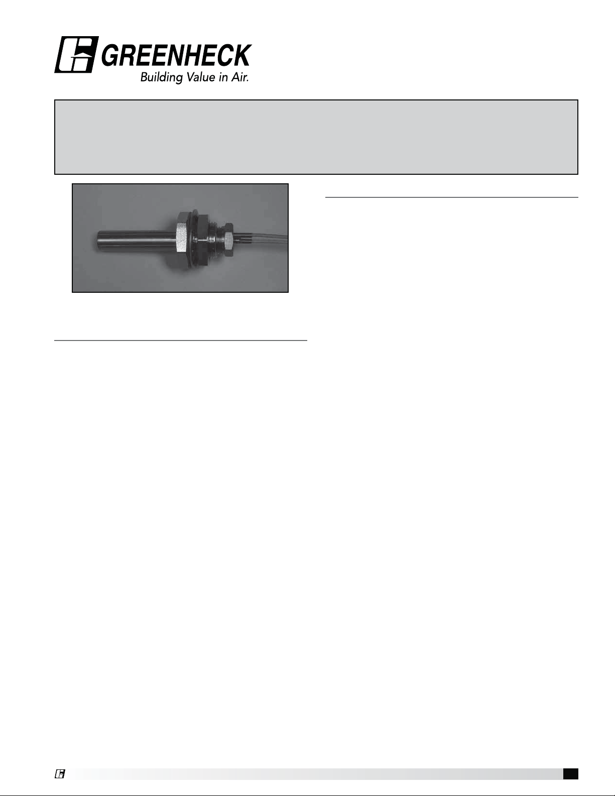
on once heat is detected. The interlock consists of an
adjustable thermostat, junction box, Evergreen QuikSeal threaded fitting, and is contained in a stand alone
Product Specification
Temperature Interlock
International Mechanical Code (IMC) 2006 section
507.2.1.1 Compliant Electrical Package
Provide Greenheck Fan Corporation temperature
interlock electrical package as shown on plans and in
accordance with the following specification:
The temperature interlock(s) consists of an adjustable
thermostat, junction box, fire proof/leak proof threaded
fitting (Evergreen Quik-Seal® and/or Evergreen
Compression Seal), and shall be a self-contained unit
or as part of another pre-engineered electrical control
package.
The temperature interlock package shall close a relay
powering the fans when the set temperature is reached
at the thermostat. The interlock shall hold the circuit
closed upon fan switch being turned off until the
temperature at the sensor decreases below the set point
at which point the timed relay will begin a countdown.
Once the countdown has expired and as long as the
temperature has remained below the set point, the fans
shall shut down.
The temperature interlock package shall be constructed
by Greenheck Fan Corporation in accordance with
International Mechanical Code. The manufacturer shall
provide, upon request, the necessary data that confirms
compliance with the code listed above.
Due to continuous research, Greenheck Fan
Corporation reserves the right to change specifications
without notice.
box or can be added to a pre-engineered fan control
center.
Purpose
To meet IMC 2006 section 507.2.1.1, interlock between
exhaust fans and cooking equipment. This system will
utilize a temperature sensor in the exhaust duct collar
or in capture area of hood to detect heat generated
from cooking operations and automatically activate the
exhaust fans if not already turned on. Field wiring may
be required depending on location of components.
Product Application
The temperature interlock is designed to be used
with Type I and Type II Hoods. It is not to be used in
conjunction with exhaust fire dampers. Greenheck
recommends using one interlock per hood system
(activates all fans linked to system simultaneously).
Performance Goals
Automatically energize the exhaust fans when cooking
equipment generates heat. Basic controls will be
provided with a thermostat and will consist of an 8x8
electrical box with controls and a labeled terminal
strip to hook-up incoming power and fan starters.
An adjustable delay is used to keep the exhaust fans
running when the thermostat initially closes to prevent
the fan from cycling on and off at startup and shut
down. Fans will shut down automatically 20 minutes
after the thermostat opens its contact. The time delay
can be adjusted from 1-100 minutes based on jobsite
requirements.
®
Temperature Interlock
1
Page 2

Table of Contents
Product Specification ........................1
General Description ..........................1
Receiving and Handling .......................2
Installation
Hood Mounting ...........................3
Duct Collar Mounting ......................3
Electrical Connections
Thermostat Connections ...................4
Breaker Panel to Control Box or
Fan Control Center ......................4
Circuit Connections .......................4
Calibration .................................4
Control Circuit Diagrams ....................5-6
Testing ...................................7
Operation ..................................7
Troubleshooting .............................7
Maintenance ...............................7
Frequently Asked Questions ...................8
Replacement Parts ..........................8
Codes and Standards Compliance ..............8
Our Commitment ............................8
Receiving and Handling
Upon receiving the equipment, check for both obvious
and hidden damage. If damage is found, record all
necessary information on the bill of lading and file
a claim with the final carrier. Check to be sure that
all parts of the shipment, including accessories, are
accounted for. Make sure the equipment does not suffer
any heavy vibrations or knocks.
Storage
If a temperature interlock must be stored prior to
installation it must be protected from dirt and moisture.
Indoor storage is recommended. For outdoor storage,
cover the hood with a tarp to keep it clean, dry, and
protected from UV (ultraviolet) radiation damage.
Improper storage which results in damage to the unit
will void the warranty.
Temperature Interlock
2
®
Page 3
Installation
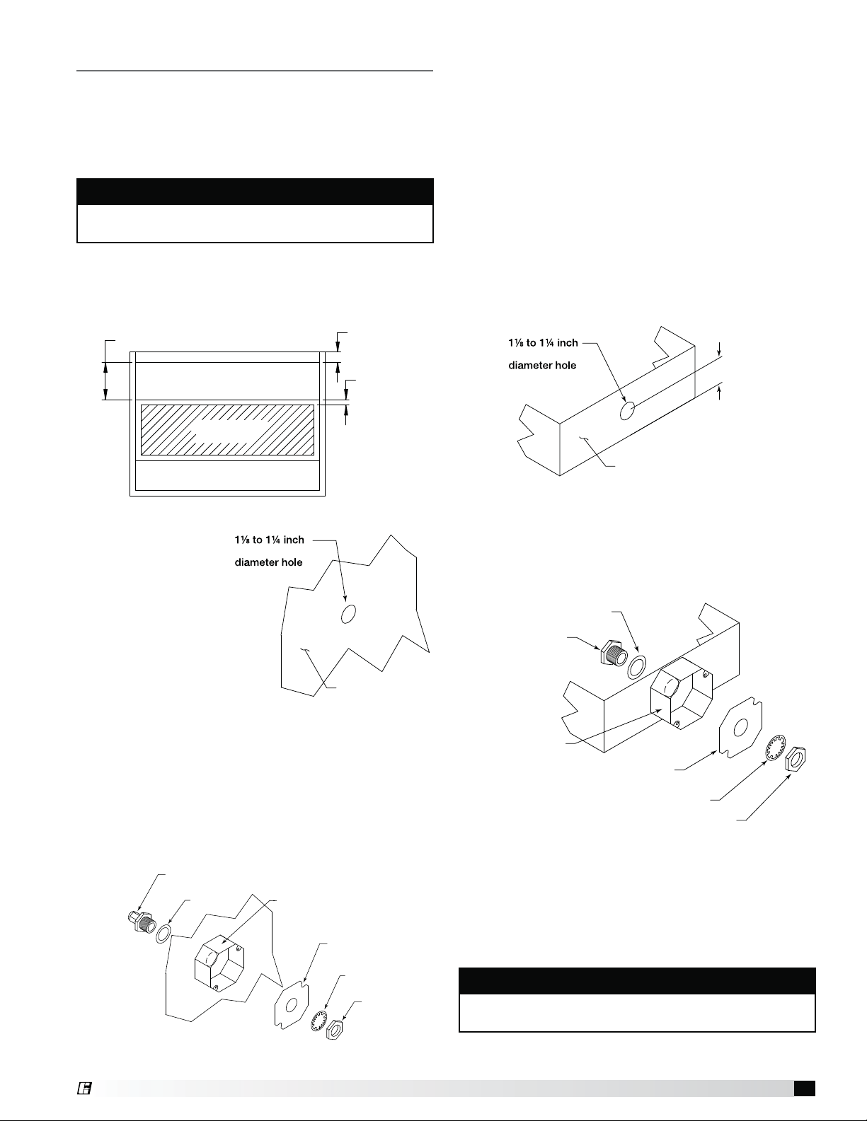
19.525 inches
3 inch air space
2 inch typical
Exhaust Area
Supply Area
(optional)
Sensor Install
(cut out area)
Control Box Mounting
Locate an area with enough space to mount the control
box and fasten to the wall. Avoid installing the control
box in environments with high magnetic and/or radio
frequency interference.
NOTE
Control box may be factory mounted. If so, continue
to the next section.
Thermostat Installation - Hood Mounting
Recommended thermostat mounting location is in the
flat interior of the hood and at least 8 inches (20.32cm)
from light fixture.
3. Place the junction box provided over the fitting on
top of the hood, keeping the fitting centered in the
box.
4. Thread the thermostat into the compression seal
fitting and tighten to 35 ft-lbs. (4.84 m-kgs).
Duct Collar Mounting
1. Locate the exhaust duct on top of the hood. A 11⁄8to
1¼-inch (28.58 to 31.75 mm) diameter hole must be
cut into the duct 2inches
top. Center the hole along the side of the duct. Make
sure that the thermostat will not interfere with any
fire system nozzles, or other items installed in the
exhaust duct. If an exhaust fire damper is present
the hood exhaust collar, it must be removed prior to
thermostat installation.
(50.8 mm) above the hood
1. Locate the flat
2. Insert the Evergreen Compression Seal fitting into
Hood Plan View
area(s) at the top
(28.58 to 31.75 mm)
interior of the hood
in front of the
filters, towards the front
of the hood. A 1
1
⁄8 to
1¼ inch (28.58 to 31.75
mm) diameter hole must
be cut into the top of
the capture tank. Make
Hood Surface
sure the thermostat will
not interfere with the fire system nozzles and is not
within 8 inches
(20.32cm) of the light fixtures.
the hole from the inside of the hood, making sure the
gasket is placed on the fitting before inserting it into
the hole. Install the lock washer and 11⁄2inch (38mm)
nut on the threaded portion of the compression seal
fitting and tighten securely.
Compression Seal
PN 452614
Gasket
Exploded View (Components)
Octagon Extension
PN 830125
Junction Box Plate
PN 732396
Lock Washer
Nut
(28.58 to 31.75 mm)
Hood Exhaust Collar
(front side)
2 inches
(50.8 mm)
2. Insert the Evergreen Quik-Seal fitting into the hole
from the inside of the duct, making sure the gasket is
placed on the fitting before inserting it into the hole.
Install the lock washer and 1
1
⁄2inch (38.1mm) nut
on the threaded portion of the Evergreen Quik-Seal
fitting and tighten securely.
Gasket
1/2 inch Quik-Seal
Octagon Extension
PN 451168
PN 830125
Junction Box Plate
PN 732396
Lock Washer
Nut
Exploded View (Components)
3. Place the junction box provided over the fitting
and tack weld the junction box to the exhaust duct
keeping the fitting centered in the box. (Welding
optional).
4. Thread thermostat into Evergreen Quik-Seal fitting
and tighten to 35 ft-lbs
(4.84 m-kgs).
NOTE
All field installation and wiring of electrical equipment
must be done to meet NEC and local codes.
®
Temperature Interlock
3
Page 4
Electrical Connections
Thermostat Connections
1. Run two 14 awg 90°C minimum conductors from
each temperature sensor to the appropriate electrical
circuit connections. (See Step 3 for connection
options).
2. In junction box, connect leads on thermostat to the
14 awg conductors using appropriate size
wire nuts.
• Wires are interchangeable with one another.
• Wire thermostats in parallel if there are multiple
thermostats utilized.
3. The thermostat(s) wires will land on terminals T1-A
and T1-B
CAUTION
Do not connect temperature sensor in series with
each other, nor in series with fan power. This can
permanently damage the sensors. On/off cycling
of the fans will result during start-up and shutdown
periods. Use the thermostat for control wiring only.
Calibration
Thermostat is preset by factory to 95°F and has a
slow make and break contact. It will make contact on
a temperature rise and break contact on temperature
fall. The temperature set point may have to be adjusted
slightly depending of both ambient and cooking
conditions. The adjustment knob is located on the back
of the thermostat. Use a small blade screwdriver to
make the adjustments.
1. Turn counterclockwise to increase the temperature
set point, turn clockwise to decrease the
temperature set point.
2. Quarter revolution in either direction corresponds
to a 22.5°F adjustment. Be sure to make small
adjustments, about 1/16 of a turn (≈6°F) or less at
one time.
3. Do not exceed more than one-half revolution in either
direction.
4. Check system operation before making additional
adjustments.
Switch Connections to Control Box or Fan Control
Center
1. Connect a Single Pole Single Throw (SPST) switch
to terminals S1H and S1. This is the same whether
temperature interlock is in a separate control box or
integrated with a kitchen fan control center.
Circuit Connections
1. Standard Interlock Control
• 120VAC, 10 or 15 amp circuit to terminals H1
and N1
• 120VAC, 24VAC or other control circuit for fan
starter activation (factory separated from main
power connection shown in previous bullet)
- Control circuit power to terminal CP1
- Terminal CP2 to fan starter coils (hot)
2. Kitchen Fan Control Center Integration (KFCC)
• 120VAC, 15 amp circuit to H1 and N1 in fan
control center
- No additional control circuits are required
- Fan starters are factory-wired
Temperature Interlock
4
®
Page 5
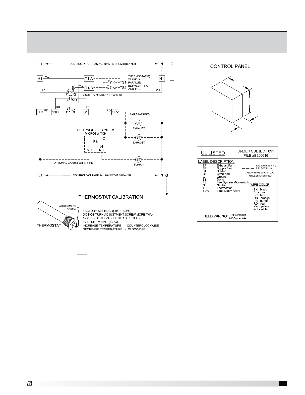
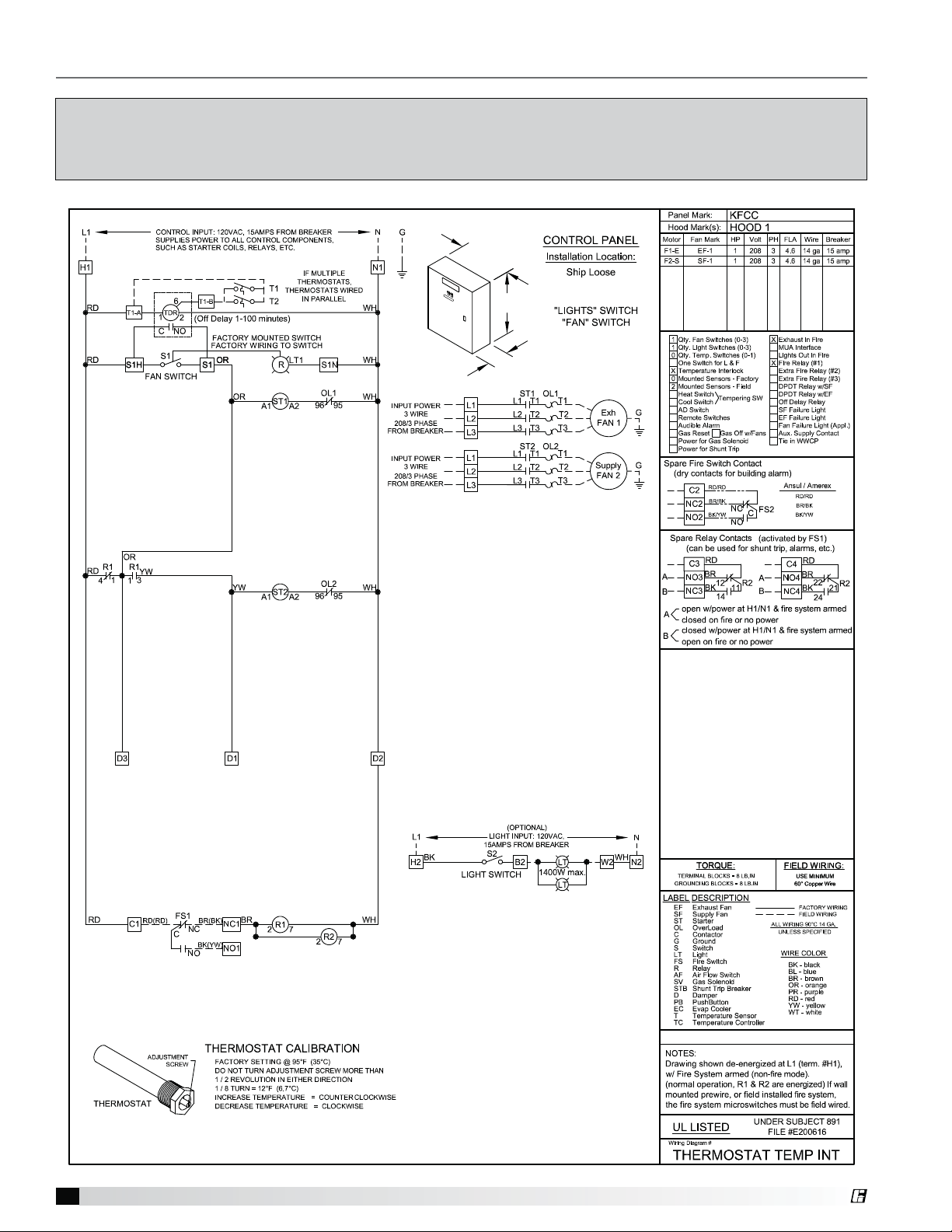
Control Circuit Diagram (Standard Control)
This is an example of a generic wiring diagram for standard control. It provides temperature interlock
function for two exhaust fans and one supply fan. (All starters provided by others, external to this control box).
8 inches
8 inches
4 inches
This Control Panel only provides control power to signal operation of supply and exhaust starters.
Starters are NOT provided by manufacturer. Starters to be provided by, wired and mounted by others.
®
Temperature Interlock
5
Page 6
Control Circuit Diagram (Fan Control Center)
This is an example of a generic wiring diagram for temperature interlock integration into a KFCC.
It provides temperature interlock function for one exhaust fan and one supply fan.
To see your job specific drawing, look on the inside panel of the KFCC cabinet.
12 inches
LIG
H
T
S FANS
18 inches
6 inches
Temperature Interlock
6
®
Page 7
Testing
Troubleshooting
1. Turn fan switch on, then off to ensure proper fan
operation before cooking equipment is started. Once
this is verified, testing can proceed.
2. For testing only, locate the time delay relay. Turn the
time adjustment knob counterclockwise to the first
mark in order to expedite the testing process. Make
a note as to where the timer was originally set.
3. Heat up cooking equipment with fans off. Once the
temperature reaches the set point of the thermostat
the fans will start, preferably within 5minutes. If the
fans take more than 5 minutes to start, decrease
the temperature set point by turning the adjustment
screw 1/16 turn clockwise. Do not apply direct flame
to the thermostat
4. If an adjustment was made in Step 3, repeat now.
5. After verification of fan start-up, shut down cooking
equipment. The fan switch should still be in the off
position. Once cooking equipment has cooled, the
thermostat will open triggering the timer to begin.
Once time has expired, the fans will shut down.
Thermostat operation can be verified by checking
voltage (120V) between T1-B and neutral on either
the control box or KFCC. 120V will be present when
the thermostat senses heat.
6. Once proper operation has been verified, set
the dial on the timer relay to its original setting
(approximately 20 minute delay).
Fans do not turn on automatically upon cooking
equipment activation.
• Check wiring to control panel or relay box,
thermostats must be wired in parallel
• Temperature set point to high, decrease set point
• No power to fans, check breakers/starters/relays
Fans do not shut off.
• Switch must be in the off position
• Cooking equipment hot, wait for it to cool
• Temperature set point too low, increase set point
• Ensure wires connected to appropriate control
circuit
• Time delay too great, turn down timer
Fans do not turn on quick enough.
• Decrease temperature set point
Maintenance
Daily
Clean thermostat with cloth and degreaser. Keep clean
for best performance. (Can clean weekly depending
upon grease accumulation).
Weekly
Dependant on grease production and grease filter type,
clean thermostat.
CAUTION
The probes should never be exposed to direct flame.
This can cause permanent damage to the probe.
NOTE
During testing, if fans do not start automatically in
the first 10 minutes of cooking equipment activation,
manually start fans to avoid accidental fire system
dump due to heat build-up.
Operation
1. Turn fans on and off using the fan switch. It is normal
for the fans to remain running after the switch is
turned off. The exhaust thermostat will open after
heat is no longer present under the hood which will
activate the timer to begin its countdown. Once
time has expired, fans will shut down. The timer is
adjustable from 1-100 minutes. The recommended
time delay setting is approximately 20 minutes.
2. In the event that the cooking equipment is started
without turning the fans on manually, the fans will
turn on automatically and remain running with the
presence of heat under the hood. The exhaust
thermostat will open after heat is no longer present
under the hood which will activate the timer to begin
its countdown. Once time has expired, fans will shut
down.
Seasonal
May have to change temperature setting on back of
thermostat if ambient kitchen temperatures fluctuate
between summer and winter seasons.
Whom to call
Contact your local Greenheck representative.
What to have ready for the call
Sales order, serial number and description of product.
Sales Order Number ________________________
Serial Number ______________________________
®
Temperature Interlock
7
Page 8
Frequently Asked Questions
Replacement Parts
What temperature is the thermostat set from the
factory?
95º Fahrenheit.
Will the temperature interlock automatically start/
stop the fans?
When connected properly to fan starters the
temperature interlock will automatically control
the fans without input from the user. However, it is
intended to be used as a back-up to manual control.
May I connect the power going to my fan directly
through the control box?
No, the control box should only use control voltage
only (24-120V), and a separate 120V power source
is required to run the temperature interlock controls.
Greenheck recommends the use of starters sized for
each fan.
What is the purpose of the timer in the control box?
The timer is used to delay the shut down of the fans
to prevent fan on/off cycling while the temperature
in the exhaust duct can reach steady state. Without
the delay, cycling could occur both on startup
or shutdown of cooking equipment. The delay is
typically set at 20 minutes.
Can I use one control box for multiple hood systems?
This can be done, however, it is not recommended.
Any one of the thermostats would turn on all hoods
running on that control box. It is better to have one
hood/fan per control box, plus a significant energy
savings can be obtained if one or more of the hoods
is not in operation.
Can I still turn my fan on and off?
Yes, the temperature interlock is designed to be
operated with a typical on/off switch. The fan may not
turn off immediately after turning the fan switch off, it
will sense when the cooking operations have cooled
and then turn off.
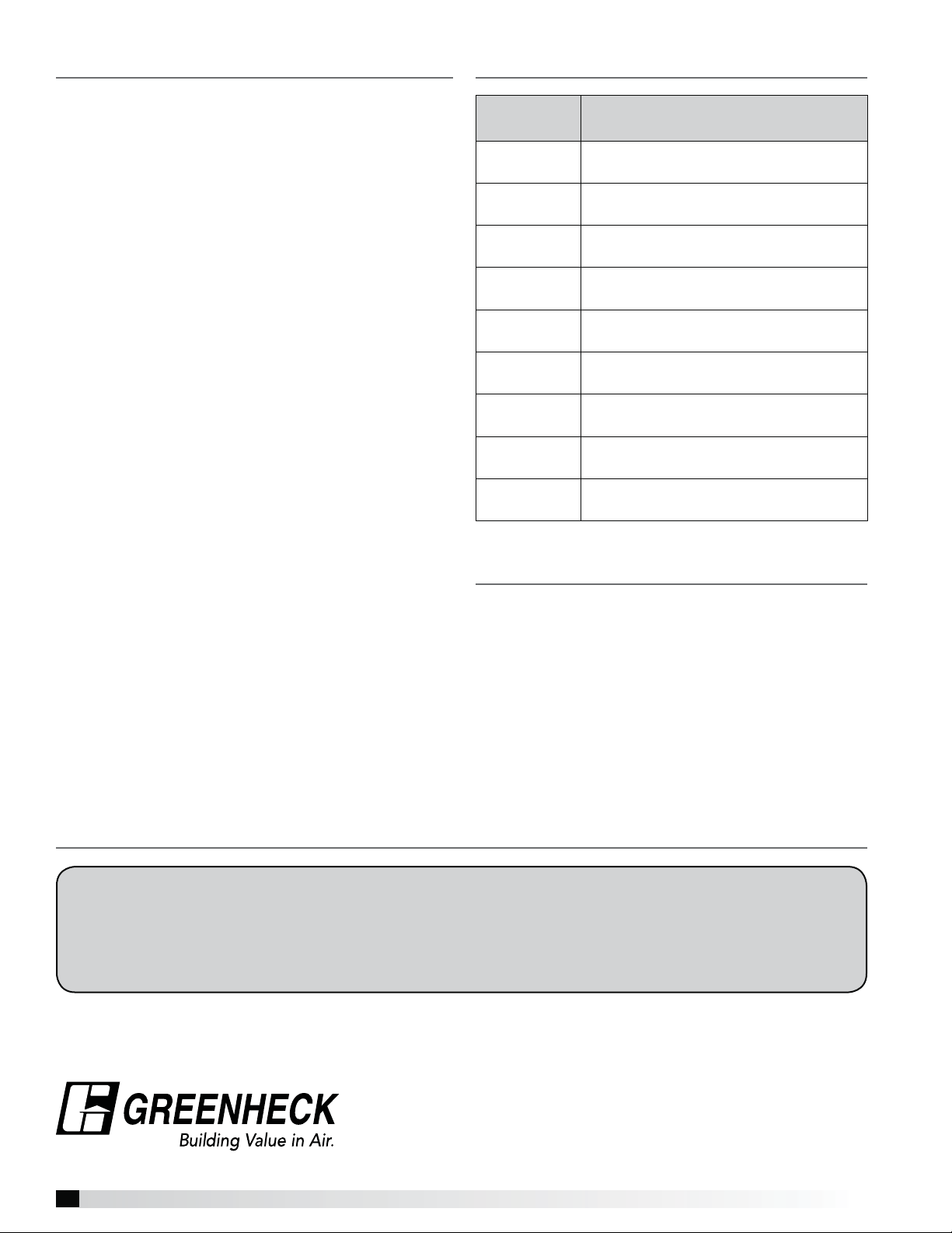
Part
Number
383923
451168
830125
380926
381460
384905
384908
383271
452614
Thermostat, Vulcan
1C2B9 5/8-inch Type C
Evergreen Quik-Seal, 1/2-inch
#171 (1-1/8 inch hole size)
Extension, Octagon (drilled)
SC55151-1/2 (380928)
Cover, Octagon Box
SC#54-C-1RACO 722
Enclosure, 8X8X4 NEMA3R
ELMATE RC-884-SC3R
Terminal Block, Single Pole,
DIN-RAIL MT, ABB ZS6
Jumper, DIN-RAIL
Terminal Block 2 Pole ABB JB6-2
Timer SSAC
#KRDB424 SPST 1-100 min.
Evergreen Compression Seal,
5/8-inch, #302
Description
Codes and Standards Compliance
• UL 710
• National Fire Protection Association (NFPA 96)
• International Mechanical Code (IMC) 2006
Section 507.2.1.1
Our Commitment
As a result of our commitment to continuous improvement, Greenheck reserves the right to change specifications
without notice.
Specific Greenheck product warranties are located on greenheck.com within the product area tabs and in the
Library under Warranties.
AMCA Publication 410-96, Safety Practices for Users and Installers of Industrial and Commercial Fans, provides additional safety
information. This publication can be obtained from AMCA International, Inc. at www.amca.org.
®
Phone: (715) 359-6171 • Fax: (715) 355-2399 • E-mail: gfcinfo@greenheck.com • Website: www.greenheck.com
471738 • Temperature Interlock, Rev. 2, November 2012 Copyright 2012 © Greenheck Fan Corporation
8
 Loading...