

Page 1
Document 460983
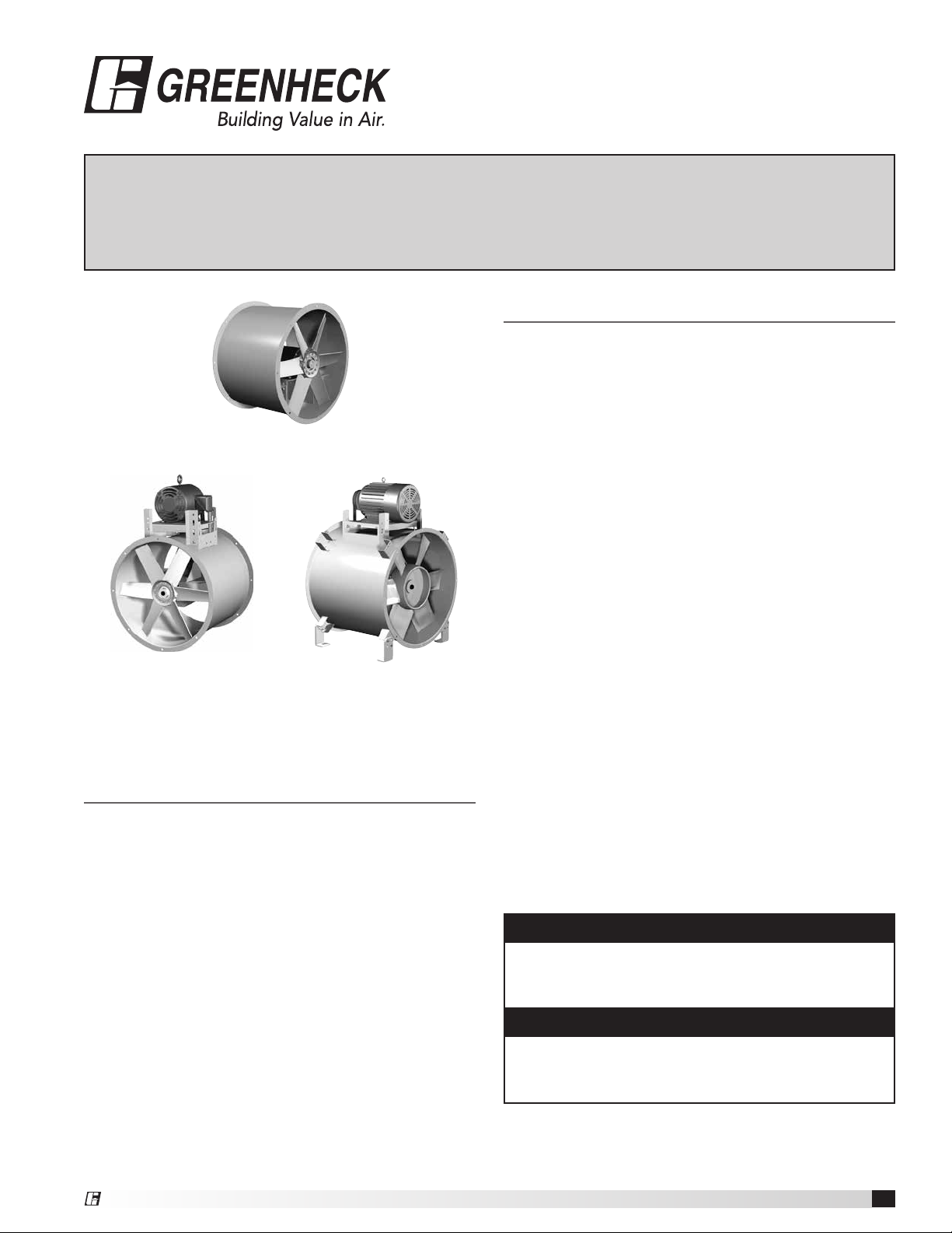
Models TDI,
®
TBI-CA and TBI-FS
Installation, Operation and Maintenance Manual
Please read and save these instructions for future reference. Read carefully before attempting to assemble,
install, operate or maintain the product described. Protect yourself and others by observing all safety
information. Failure to comply with instructions could result in personal injury and/or property damage!
General Safety Information
Only qualified personnel should install this unit.
Personnel should have a clear understanding of these
instructions and should be aware of general safety
precautions. Improper installation can result in electric
shock, possible injury due to coming in contact with
TDI
TBI-CA
Level 3, 4 and 5
Cast Aluminum Propeller
Fabricated Steel Propeller
TBI-FS
Level 3, 4 and 5
Table of Contents
Receiving, Unpacking Handling and Storage ...... 2
Removing from Storage ...................... 2
Lifting ..................................... 3
Effects of Installation on Performance ........... 3
Typical Installation ........................... 4
Operation and Unit Start-Up
Electrical Connections ..................... 5
Pre-Start-Up Checks ...................... 5
Maintenance
Fasteners and Set Screws .................. 6
Bearings ................................ 6
Lubrication bearings and motor .............. 6
Motor .................................. 6
Belts ................................... 6
Removal of dust, dirt and debris ............. 7
Parts List .................................. 7
Commitment ............................... 8
moving parts, as well as other potential hazards. Other
considerations may be required if high winds or seismic
activity are present. If more information is needed,
contact a licensed professional engineer before moving
forward.
1. Follow all local electrical and safety codes, as well
as the National Electrical Code (NEC), the National
Fire Protection Agency (NFPA), where applicable.
Follow the Canadian Electric Code (CEC) in Canada.
2. The rotation of the propeller is critical. It must
be free to rotate without striking or rubbing any
stationary objects.
3. Motor must be securely and adequately grounded.
4. Do not spin fan propeller faster than the maximum
cataloged fan rpm. Adjustments to fan speed with
Variable Frequency Drives (VFD) may affect motor
load. If the fan RPM is changed, the motor current
should be checked to make sure it is not exceeding
the motor nameplate amps.
5. Do not allow the power cable to kink or come in
contact with oil, grease, hot surfaces or chemicals.
Replace cord immediately if damaged.
6. Verify that the power source is compatible with the
equipment.
DANGER
Always disconnect power before working on or near a
unit. Lock and tag the disconnect switch or breaker to
prevent accidental power up.
CAUTION
When servicing the unit, motor may be hot enough
to cause pain or injury. Allow motor to cool before
servicing.
®
Tubular Inline Fans
1
Page 2

Receiving
Upon receiving the product, check the bill of lading to
ensure all items were received. Inspect each crate for
shipping damage before accepting delivery. Notify the
carrier if any damage is noticed. The carrier will make
notification on the delivery receipt acknowledging any
damage to the product. All damage should be noted on
all the copies of the bill of lading which is countersigned
by the delivering carrier. A Carrier Inspection Report
should be filled out by the carrier upon arrival. If
damaged upon arrival, file claim with carrier. Any
physical damage to the unit after acceptance is not the
responsibility of Greenheck Fan Corporation.
Unpacking
Verify that all required parts and the correct quantity
of each item have been received. If any items are
missing, report shortages to your local representative to
arrange for obtaining missing parts. Sometimes it is not
possible that all items for the unit be shipped together
due to availability of transportation and truck space.
Confirmation of shipment(s) must be limited to only
items on the bill of lading.
Handling
Handle in such a manner as to keep from scratching
or chipping the coating. Fans should not be lifted by
the motor shaft, motor housing or fan accessories.
Damaged finish may reduce ability of unit to resist
corrosion.
Storage
Units are protected against damage during shipment. If
the unit cannot be installed and operated immediately,
precautions need to be taken to prevent deterioration of
the unit during storage. The user assumes responsibility
of the unit and accessories while in storage. The
manufacturer will not be responsible for damage during
storage. These suggestions are provided solely as a
convenience to the user.
INDOOR — The ideal environment for the storage of
units and accessories is indoors, above grade, in a
low humidity atmosphere which is sealed to prevent
the entry of blowing dust, rain, or snow. Temperatures
should be evenly maintained between 30°F (-1°C)
and 110°F (43°C) (wide temperature swings may
cause condensation and “sweating” of metal parts).
All accessories must be stored indoors in a clean, dry
atmosphere.
Remove any accumulations of dirt, water, ice, or snow
and wipe dry before moving to indoor storage. To avoid
“sweating” of metal parts allow cold parts to reach room
temperature. To dry parts and packages, use a portable
electric heater. Leave coverings loose to permit air
circulation and to allow for periodic inspection.
The unit should be stored at least 3½ inches (89 mm)
off the floor on wooden blocks covered with moisture
proof paper or polyethylene sheathing. Aisles between
parts and along all walls should be provided to permit
air circulation and space for inspection.
OUTDOOR — Units designed for outdoor applications
may be stored outdoors, if absolutely necessary. Roads
or aisles for portable cranes and hauling equipment are
needed.
The fan should be placed on a level surface to prevent
water from leaking into the unit. The unit should be
elevated on an adequate number of wooden blocks so
that it is above water and snow levels and has enough
blocking to prevent it from settling into soft ground.
Locate parts far enough apart to permit air circulation,
sunlight, and space for periodic inspection. To minimize
water accumulation, place all unit parts on blocking
supports so that rain water will run off.
Do not cover parts with plastic film or tarps as these
cause condensation of moisture from the air passing
through heating and cooling cycles.
Inspection and Maintenance during Storage
While in storage, inspect fans once per month. Keep a
record of inspection and maintenance performed.
If moisture or dirt accumulations are found on parts,
the source should be located and eliminated. At each
inspection, rotate the fan propeller by hand ten to fifteen
revolutions to distribute lubricant on motor. Every three
months, the fan motor should be energized. If paint
deterioration begins, consideration should be given to
touch-up or repainting. Fans with special coatings may
require special techniques for touch-up or repair.
Machined parts coated with rust preventive should be
restored to good condition promptly if signs of rust
occur. Immediately remove the original rust preventive
coating with petroleum solvent and clean with lint-free
cloths. Polish any remaining rust from surface with
crocus cloth or fine emery paper and oil. Do not destroy
the continuity of the surfaces. Wipe thoroughly clean
with Tectyl® 506 (Ashland Inc.) or the equivalent. For
hard to reach internal surfaces or for occasional use,
consider using Tectyl® 511M Rust Preventive or WD-40®
or the equivalent.
REMOVING FROM STORAGE — As units are removed
from storage to be installed in their final location, they
should be protected and maintained in a similar fashion,
until the equipment goes into operation.
Prior to installing the unit and system components,
inspect the unit assembly to make sure it is in working
order.
1. Check all fasteners on the fan, propeller, motor base,
and accessories for tightness.
2. Rotate the fan propeller by hand and assure no parts
are rubbing.
3. Fans should not be lifted by the motor shaft, motor
housing or fan accessories.
Tubular Inline Fans
2
®
Page 3
Lifting
DISCHARGE DUCT TURNS
1 Fan
Dia.
Good
Poor
3 Diameters of
Straight Duct
DISCHARGE DUCT TURNS
INLET DUCT TURNS
Air Flow
Air Flow
Fans should not be lifted by the motor, motor shaft,
motor cover, belt guard, tie down points, belt tube,
damper frame, windband, or fan accessories.
Flanged Housing Only
Use a minimum of four bolt holes, two per flange, or
attach two suitable chains / straps around the entire fan
housing, one near each duct flange when lifting large
horizontal fans. Secure the fan housing to prevent the
weight of a top or side mounted motor from rotating the
housing while being lifted.
For vertical hanging installations, attach a suitable lifting
device to the fan housing or inlet/outlet flange.
With Mounting Brackets
Fans are to be rigged by either the optional brackets
provided or by the skid when a forklift is used. Slings
can be attached as described above or to mounting
brackets located at the ends of the fan housing.
Effects of Installation on
Performance
Any installation with inlet or discharge configurations
that deviate from these recommendations may result in
reduced fan performance. Restricted or unstable flow
at the fan inlet can cause pre-rotation of incoming air or
uneven loading of the fan propeller yielding large system
losses and increased sound levels. Free discharge or
turbulent flow in the discharge ductwork will also result
in system effect losses.
The most common inlet and discharge conditions which
affect fan performance are:
Inlet Duct Turns
1 Fan
Dia.
Turning
Vanes
Lifting Point
(4 places)
Roof Upblast
Attach a suitable chain or strap to the four (4) windband
gussets located between the butterfly damper section of
the fan and the exterior windband unless welded lifting
lugs are provided on fan housing. Carefully lift the fan to
the roof curb and install fasteners in all holes provided
in the unit base. The windband need not be removed for
the lifting operation. A spreader bar is recommended to
prevent damage to the damper section when lifting.
Good Poor
Installation of a duct turn or elbow too close to the
fan inlet reduces fan performance because air is
loaded unevenly into the fan prop. To achieve full fan
performance there should be at least one to two fan
diameters between the turn or elbow and the fan inlet.
Discharge Duct Turns
Poor
3 Diameters of
Straight Duct
Good
Fan performance is reduced when duct turns are made
immediately off the fan discharge. To achieve cataloged
fan performance, there should be at least three
equivalent fan diameters of straight ductwork between
the fan discharge and any duct turns.
®
Tubular Inline Fans
3
Page 4

D
A
C
Optional
Mounting
Rails
Typical Installations
With Mounting Brackets
Following are typical mounting installations for models
with mounting brackets. Diagrams show dimensions for
ceiling hung installations. The dimensions for floor or
base mount installations are mirror images of these.
For TBI models with motor in the 3 or 9 o’clock position
or vertical installations, additional mounting rails are
recommended. Mounting rail dimensions are shown for
field fabrication.
Horizontal
A
Vertical
D
A
B
C
B
C
Motor at 3 or 9 o’clock position
Optional
Mounting
Rails
Continuous Duty and Emergency Exhaust
TBI-FS with optional high temperature construction
are factory-modified for operation in high temperature
continuous duty applications. With propeller on the
discharge end of the fan, negative pressure is created in
the belt tube during operation. Ambient air is drawn in
through the belt tube and cools the belts and bearings.
For the greatest amount of internal cooling, discharge
static pressure should be kept to a minimum while
keeping most of the pressure on the inlet side. Locate
the fan at ends of the duct runs and near the discharge
point in the system. This set-up will promote the
ambient air cooling effect.
Roof
Ambient temperature
not to exceed 120°F
Duct to heat source
Minimum duct
Airflow
Cooling air for
drives and
bearings
Wall and/or ceiling should enclose
fan when used for emergency heat
and smoke exhaust.
at discharge
Optional
Mounting
Rails
Mounting Hole Locations
A B
Fan
Size
Belt
Drive
Direct
Driect
Belt Drive Direct Drive
Level 3Level
Level 3Level
4/5
4/5
18 17.63 17.63 17.38 21.38 13.38 21.38 26.00 28.00
20 19.00 19.00 17.38 22.38 14.38 21.38 28.50 29.25
24 21.88 21.88 18.38 23.38 14.38 21.38 33.00 33.75
30 26.13 26.13 19.38 28.38 16.38 25.88 37.00 38.75
36 30.50 30.50 21.88 26.88 13.88 23.38 44.00 47.00
42 34.75 34.75 22.88 31.88 19.88 26.38 50.00 51.25
48 42.00 42.00 25.38 36.38 19.38 31.38 56.00 61.00
54 46.75 46.75 29.88 40.38 NA 31.38 62.00 65.50
60 51.00 51.00 32.38 41.38 NA 31.38 71.00 70.00
Dimensions shown are in inches.
C
Belt
Drive
To determine unit level, refer to the fan nameplate.
Example TBI-3L42 (level 3) or TBI-4H30 (level 4)
D
Belt
Drive
Tubular Inline Fans
4
®
Page 5

Operation and Unit Start-Up
Electrical Connections
The electrical supply must be compatible with the
fan motor voltage, phase and amperage capacity.
The electrical supply line must be properly fused and
conform to local and national electrical codes.
For direct drive units, the electrical supply may be
routed internally and exit through a hole provided in the
fan housing if an optional service disconnect switch is
provided.
For belt drive units, the electrical supply line may be
routed internally and exit the fan housing through a hole
provided below the belt tube opening. The electrical
supply line should then be either: (1) connected to an
optional service disconnect switch, or (2) wired directly
to the motor.
For belt drive units in continuous high
temperature installations, the electrical supply
must be kept out of the airstream. This means bringing
the supply lines off the roof deck not through the fan.
The electrical supply line should then be either: (1)
connected to an optional service disconnect switch, or
(2) wired directly to the motor.
The supply wires are then connected to an optional
safety disconnect switch (if supplied) or wired directly to
the motor.
For belt drive units in emergency smoke removal
installations, the electrical supply must be kept out of
the airstream. They may also require an isolated power
supply so that if power is cut to the building in the event
of a fire, the fan will continue to operate. Check the
local and national electrical codes for emergency smoke
removal fans.
Pre-Start-Up Checks
1. Check all fasteners for tightness. This includes motor
bolts, bearing bolts, and any set screws or locking
collars attaching the propeller to the shaft and shaft
to the bearings.
If roof upblast configuration, lift the butterfly dampers
to verify they open and close without binding.
2. Rotate the propeller by hand
to ensure it turns freely and
does not rub on the fan tube.
Propeller rotation should always
be checked by turning the unit
on momentarily. Rotation should
be in the same direction as the
Rotation
rotation decal affixed to the unit. Actual direction
of rotation will vary by model. To reverse rotation
on three phase installations, simply interchange
two of the three electrical leads. For single phase
installations, follow the wiring diagram located on the
motor.
3. Belt Drive Fan RPM - adjustable motor pulleys are
preset at the factory for the specified fan RPM. Fan
speed can be increased by closing or decreased by
opening the adjustable pulley. Multi-groove variable
pitch pulleys must be adjusted an equal number of
turns open or closed.
4. Belt Drive Roof Upblast Fan RPM - adjustable
motor pulley on motors less than 10 HP is preset
at the factory to the customer-specified RPM. Fan
speed can be increased or decreased by adjusting
the pitch diameter of the motor pulley. Multi-groove
variable pitch pulleys must be adjusted an equal
number of turns open. Motors 10 HP and larger will
have a constant speed pulley.
NOTE
Any change, increase or decrease, in fan speed
can represent a substantial increase in horsepower
required from the motor. Always check motor load
amperage and compare to nameplate rating when
changing fan speed.
®
Tubular Inline Fans
5
Page 6

Maintenance
Belt Span
Deflection =
Belt Span
64
CORRECT WRONG
WRONG WRONG
Belt Span
Deflection =
Belt Span
64
WARNING
Always disconnect power before working on or near a
unit. Lock and tag the disconnect switch or breaker to
prevent accidental power up. Failure to comply with
this safety precaution could result in serious injury or
death.
Once the fan has been put into operation, a periodic
maintenance program should be set up to preserve the
reliability and performance of the fan.
Items to be included in this program are:
• Fasteners and set screws
• Bearings
• Lubrication of bearings and motor
• Belts
• Removal of dust, dirt and debris
• Dampers for roof upblast configuration
Fasteners and Set Screws - Normal fan vibration has
a tendency to loosen mechanical fasteners. Periodic
inspection should include checking all fasteners, set
screws, and locking collars attaching the propeller to
the shaft and the shaft to the bearings. Loose bearing
set screws and locking collars will lead to premature
failure of the fan shaft.
Bearings on belt drive fans - Bearings are the most
critical moving part of the fan and should be inspected
at periodic intervals. Locking collars and set screws,
in addition to fasteners attaching the bearing to the
bearing plate, must be checked for tightness.
In a clean environment and temperature between 32°
and 200°F (0 to 93°C), fan shaft bearings with grease
fittings should be lubricated semi-annually using a high
quality lithium based grease. Bearings operating outside
these temperature parameters require special high
or low temperature grease. If unusual environmental
conditions exist, such as temperatures below 32°F
(0°C) and above 200°F (93°C), high moisture, or
contaminants, more frequent lubrication is required.
With the unit running, add grease very slowly with a
manual grease gun. Be careful not to unseat the seal by
over lubricating or using excessive pressure. Bearings
without grease fittings are lubricated for life.
Bearings are one of the most critical parts of a fan and
should be inspected at regular intervals. Locking collars,
set screws and fasteners attaching the bearings to the
fan should also be checked.
Model TBI fans are equipped with extended lubrication
lines as standard. The grease fittings are located on the
exterior of the fan housing next to the motor cover and
should be wiped clean before adding grease.
Motors - Lubrication of motors is intended only when
fittings are provided. Many fractional horsepower
motors are permanently lubricated for life and require
no further lubrication. Motors supplied with grease
fittings should be greased in accordance with the
manufacturer’s directions on the motor nameplate.
Belts - Premature belt failures are frequently caused
by improper belt tension (either too loose or too tight),
misaligned pulleys, or by prying belts on and off pulleys.
The proper tension for operating a V-belt is the lowest
tension at which the
belts will not slip at peak
Fig. 2
load conditions. For
initial tensioning, the
proper belt deflection is
1/64-inch for each inch
of belt span, measured
half way between the
pulley centers.
For example, if the belt span is 64 inches, the belt
deflection should be one inch using moderate thumb
pressure at midpoint of the drive (Fig. 2).
Check belt tension two times during the first 24 hours of
operation, after 100 hours of operation, and periodically
thereafter. To adjust belt tension, simply pivot the motor
on the motor plate. Use the bolts in the slotted brackets
and adjustment rods with bolts as adjustment points
until proper belt tension is attained.
It is very important that the drive pulleys remain in
proper alignment after adjustments. (Fig. 3)
Fig. 3
CORRECT WRONG
WRONG WRONG
When replacing belts, always use the same size and
type as originally supplied by the factory. Check pulleys
for wear and replace both pulleys and belts if wear is
evident. Misalignment of pulleys will result in premature
belt and bearing failure, noise and loss of fan efficiency.
Tubular Inline Fans
6
®
Page 7

Removal of dust, dirt and debris - Dirt clogs cooling
openings on the motor housing, contaminates bearing
lubricant, and collects on the propeller causing severe
imbalance if left unchecked.
Periodically, thoroughly clean the exterior surface only
of the motor. If optional motor cover is installed, remove
it and clean the motor of dust, dirt and debris to aid
in motor cooling. Use caution and do not allow water
or solvents to enter the motor or bearings. Under no
circumstances should motors or bearings be sprayed
with steam or water.
Accumulations of dirt and debris on the propeller
blades may cause an unbalanced condition resulting
in excessive vibration and premature failure of the
propeller and bearings.
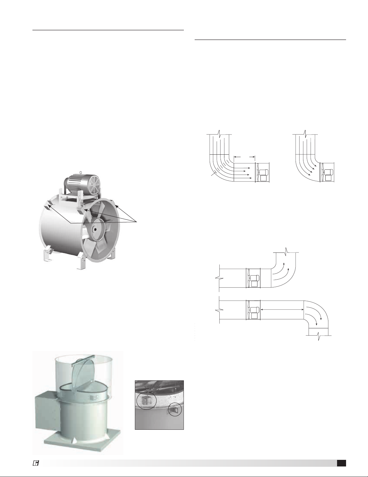
Dampers for Roof Upblast Configuration - If
exhausting dirty or contaminated air, the propeller
and butterfly damper assembly should be cleaned
periodically. Excessive buildup of dirt on the damper
blades may cause binding and sticking blade hinges
resulting in loss of fan performance. Clean as needed.
These fans have heavy-duty fusible link damper lifters
under very high spring tension that must be pinned so
they cannot be accidentally tripped when servicing the
fan. The fusible link damper lifters are located under
the butterfly damper blades. Point “A” shows where
the safety pin MUST be placed when the fan is being
serviced. Point “B” shows where the safety pin is placed
for storage when the fan is in service.
Fan sizes 24, 30 and 36 also have fusible link damper
lifters, but they do not have the ability to be pinned
when servicing due to differences in lifter designs.
In either case, extreme care must be taken when
working around the damper lifter assemblies or serious
bodily injury or death may result.
Parts List
Each fan bears a manufacturer’s nameplate with
embossed model and serial number. This information, in
addition to the shown parts diagram, will assist the local
Greenheck representative and the factory in providing
service and replacement parts.
Motor Cover
(optional)
Motor Plate
Bearing
Support
Universal
Mounting
Brackets (8)
Mounting
Supports (4)
MotorMotor Pulley
Belt
Belt Tube
Shaft Pulley
Bearing Cover
Bearings
Propeller
Shaft
®
Spring Lifter Tube
Point “B”
Pin Storage Location
Lock Plate
Fusible Link Assembly
Point “A”
Install pin here to
lockout damper fifters
Spring
Lifter Arm
Spring Bracket
Butterfly Dampers
Damper Hinge Rod
Windband Gussets
Weatherhood
Motor Plate
Motor
Motor Pulley
Belt(s)
Curb Cap
Inlet Guard
(optional)
Outlet Screen
Windband
Tie Down Points
Propeller
Bearing Cover
Shaft Bearings
Shaft Pulley
Fan Pulley
Access Door
Tubular Inline Fans
(optional)
(optional)
7
Page 8

Our Commitment
As a result of our commitment to continuous improvement, Greenheck reserves the right to change specifications
without notice.
Specific Greenheck product warranties are located on greenheck.com within the product area tabs and in the
Library under Warranties.
Greenheck catalogs, Medium Pressure Axial Fans and Tube
Axial Inline Fans, provides additional information describing
the equipment, fan performance, available accessories, and
specification data.
®
Phone: 715.359.6171 • Fax: 715.355.2399 • Parts: 800.355.5354 • E-mail: gfcinfo@greenheck.com • Website: www.greenheck.com
460983 • TDI, TBI-CA, TBI-FS, Rev. 2, December 2013 Copyright 2013 © Greenheck Fan Corporation
8
AMCA Publication 410-96, Safety Practices for Users and
Installers of Industrial and Commercial Fans, provides
additional safety information. This publication can be obtained
from AMCA International, Inc. at www.amca.org.
 Loading...