

Page 1
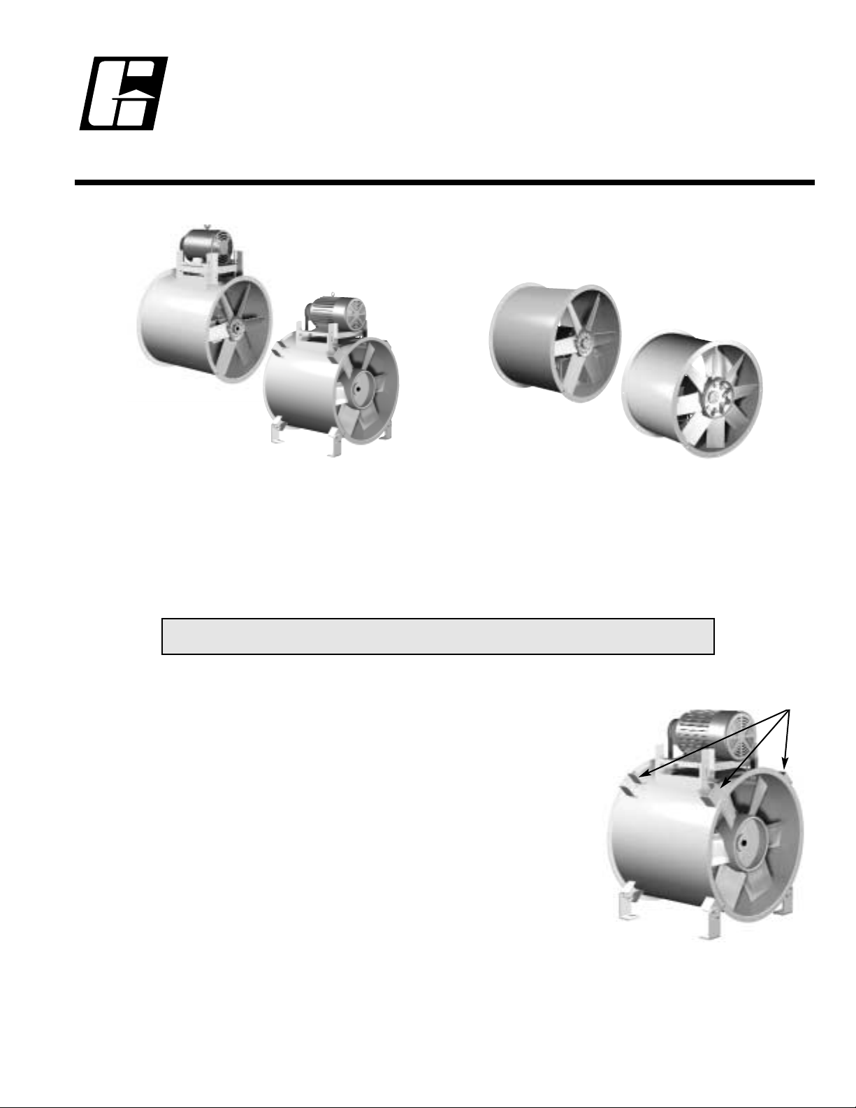
TBI Tubular Belt Inline Fan
TDI Tubular Direct Inline Fan
RECEIVING
Greenheck model TBI / TDI fans are thoroughly inspected and test run at the factory. Items such as proper propeller
alignment, balance, and workmanship are analyzed by personnel using state-of-the art equipment. However, damage may
occur during handling and shipping. Therefore, it is important that the unit be carefully inspected for visible and concealed
damage before beginning installation. In addition, check to see that all accessory items are accounted for.
STORAGE - Indoor and Outdoor
When a fan is to be stored for a period of time, it must be protected from dirt and moisture. Use of a tarp to cover the unit
will aid in keeping it clean and dry, but avoid using a black plastic tarp as it will promote condensation. Improper storage
which results in damage to the fan will void the warranty. If the storage period is lengthy, the propeller and motor should be
rotated periodically and the bearings purged with fresh grease. In humid, dusty, or corrosive atmospheres, rotate the fan and
purge the bearings once a month. Under normal conditions, this procedure should be repeated once every three months.
TDI
Level 3, 4 & 5
TBI-CA, TBI-FS
Level 3, 4 & 5
HANDLING
Fans should NOT be lifted by the shaft, housing, motor, belt guard, or any
accessories.
Units - Flanged Housing Only
Use a minimum of four bolt holes, two per flange, or attach two suitable chains /
straps around the entire fan housing, one near each duct flange, when lifting large
horizontal fans. Secure the fan housing to prevent the weight of a top or side
mounted motor from rotating the housing while being lifted.
For vertical hanging installations, attach a suitable lifting device to the fan housing or
inlet/outlet flange.
Units - With Mounting Brackets
Fans are to be rigged by either the optional brackets provided or by the skid when a
forklift is used. Slings can be attached as described above or to mounting brackets
located at the ends of the fan housing (Fig. 1).
Fig. 1
GREENHECK
P.O. BOX 410 SCHOFIELD, WISCONSIN 54476-0410
PH. 715-359-6171
www.greenheck.com
®
READ AND SAVE THESE INSTRUCTIONS
PN 460983
Installation Operation and Maintenance Manual
Report any damaged equipment to the shipper immediately!
Lifting Locations
with optional
mounting brackets
June 2001
Page 2
INSTALLATION
EFFECT OF INSTALLATION ON PERFORMANCE
Any installation with inlet or discharge configurations that deviate from these recommendations may result in reduced fan
performance. Restricted or unstable flow at the fan inlet can cause pre-rotation of incoming air or uneven loading of the fan
prop yielding large system losses and increased sound levels. Free discharge or turbulent flow in the discharge ductwork
will also result in system effect losses.
The most common inlet and discharge conditions which affect fan performance are:
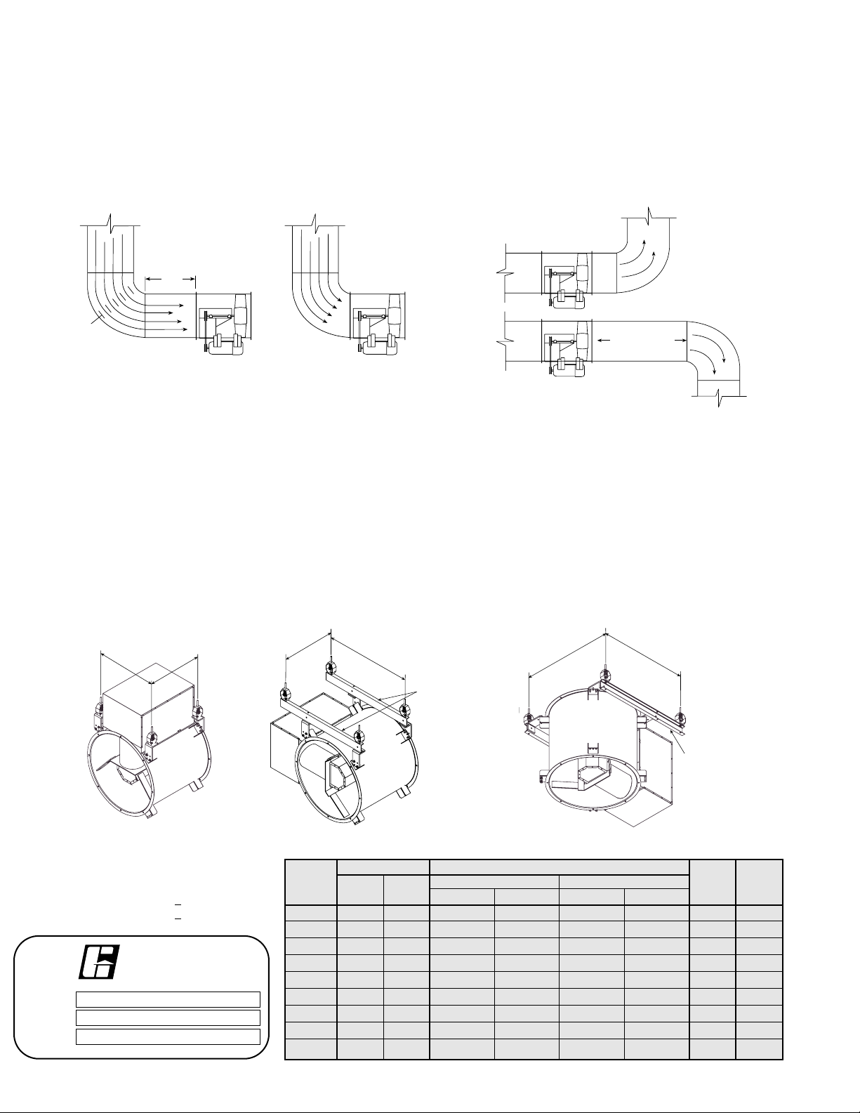
INLET DUCT TURNS
Installation of a duct turn or elbow too close to the fan inlet
reduces fan performance because air is loaded unevenly into
the fan prop. To achieve full fan performance there should
be at least one to two fan prop diameters between the turn
or elbow and the fan inlet.
DISCHARGE DUCT TURNS
Fan performance is reduced when duct turns are made
immediately off the fan discharge. To achieve cataloged
fan performance, there should be at least one equivalent
duct diameter of straight ductwork between the fan
discharge and any duct turns.
Motor at 3 or 9 o’clock position
Horizontal
Vertical
g
TYPICAL INSTALLATIONS - WITH MOUNTING BRACKETS
Following are typical mounting installations for models with mounting brackets. Diagrams show dimensions for ceiling hung
installations, the dimensions for floor or base mount installations are mirror images of these. For TBI's with motor in the 3 or
9 o'clock position or vertical installations, additional mounting rails are recommended. Mounting rail dimensions are shown
for field fabrication.
Unit Level Identification - Refer to
fan name plate
Example: TBI-3L42 (level 3)
TBI-4H30 (level 4)
TBI/TDI A B C D
Fan Belt Direct Belt Drive Direct Drive Belt Belt
Size Drive Drive Level 3 Level 4/5 Level 3 Level 4/5 Drive Drive
18 17.63 17.63 17.38 21.38 13.38 21.38 26.00 28.00
20 19.00 19.00 17.38 22.38 14.38 21.38 28.50 29.25
24 21.88 21.88 18.38 23.38 14.38 21.38 33.00 33.75
30 26.13 26.13 19.38 28.38 16.38 25.88 37.00 38.75
36 30.50 30.50 21.88 26.88 13.88 23.38 44.00 47.00
42 34.75 34.75 22.88 31.88 19.88 26.38 50.00 51.25
48 42.00 42.00 25.38 36.38 19.38 31.38 56.00 61.00
54 46.75 46.75 29.88 40.38 NA 31.38 62.00 65.50
60 51.00 51.00 32.38 41.38 NA 31.38 71.00 70.00
Mounting Hole Locations
GREENHECK
P.O. BOX 410 SCHOFIELD, WISCONSIN 54476-0410
PH. 715-359-6171
www.greenheck.com
®
MODEL
S/N
MARK
Turning
Vanes
1 Fan
Wheel
Dia.
Good Poor
Poor
Length of Straight Duct
Good
B
A
B
C
Optional
Mountin
Rails
D
C
Optional
Mounting
Rails
Page 3
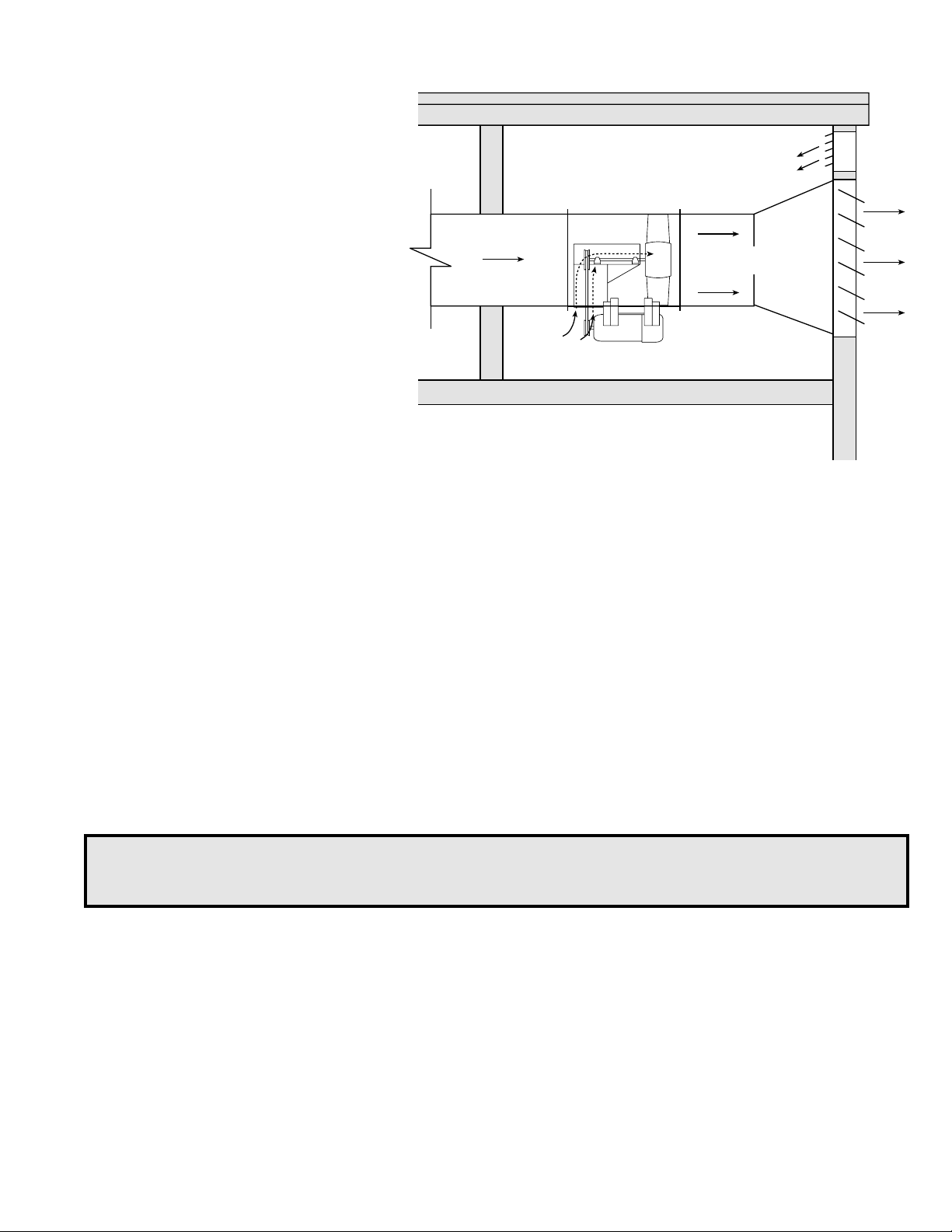
TYPICAL HIGH TEMPERATURE CONTINUOUS DUTY INSTALLATIONS
TBI-FS with optional high temperature
construction are factory modified for operation
in high temperature continuous duty
applications. With propeller on the discharge
end of the fan, negative pressure is created in
the belt tube during operation. Ambient air is
drawn in through the belt tube and cools the
belts and bearings.
For the greatest amount of internal cooling,
discharge static pressure should be kept to a
minimum while keeping most of the pressure
on the inlet side. Locate the fan at ends of the
duct runs and near the discharge point in the
system. This set-up will promote the ambient
air cooling effect.
OPERATION
ELECTRICAL CONNECTIONS
Before electrical connections are made, the supply voltage, phase and ampere capacity must be checked for compatibility
with the fan motor. In addition, the supply wiring must be properly fused and conform to local and national electrical codes.
The supply wires are then connected to an optional safety disconnect switch (if supplied) or wired directly to the motor.
PRE-START UP CHECKS
1. Check all fasteners for tightness. This includes motor bolts, bearing bolts, and any set screws or locking collars attaching
the propeller to the shaft and shaft to the bearings.
2. Prop rotation should be in the same direction as the rotation decal affixed to the unit. For 3-phase installations, fan
rotation can be reversed by simply interchanging any two of the three electrical leads. For single phase installations,
follow the wiring diagram located on the motor.
3. (Belt Drive) Adjustable motor pulleys are preset at the factory for the specified fan RPM. Fan speed can be increased by
closing or decreased by opening the adjustable pulley. Two or three groove variable pitch pulleys must be adjusted an
equal number of turns open or closed.
Note: Any change, increase or decrease, in fan speed can represent a substantial increase in
horsepower required from the motor. Always check motor load amperage and compare to name plate
rating when changing fan speed.
MAINTENANCE
Once the fan has been put into operation, a periodic maintenance program should be set up to preserve the reliability and
performance of the fan. Items to be included in this program are:
• BEARINGS • SET SCREWS • BELTS
• LUBRICATION • FASTENERS • REMOVAL OF DUST/DIRT
BEARINGS (Belt Drive)
Bearings are the most critical moving part of the fan and should be inspected at periodic intervals. Locking collars and set
screws, in addition to fasteners attaching the bearing to the bearing plate, must be checked for tightness. In a clean
environment and temperature above 32ºF (0ºC) and below 200ºF (93ºC), fan shaft bearings with grease fittings should be
lubricated semi-annually using a high quality lithium based grease. If unusual environmental conditions exist such as
temperatures below 32ºF (0ºC) and above 200ºF (93ºC), moisture or contaminants, more frequent lubrication is required.
With the unit running, add grease very slowly with a manual grease gun. Be careful not to unseat the seal by over lubricating
or using excessive pressure. Bearings without grease fittings are lubricated for life.
WARNING
Disconnect and secure to the “OFF” position all electrical power to the fan prior to inspection or
servicing. Failure to comply with this safety precaution could result in serious injury or death.
Roof
Ambient temperature
not to exceed 120∞F
Duct to heat source
Airflow
Minimum duct
at discharge
Cooling air for
drives and
bearings
Wall and/or ceiling should enclose
fan when used for emergency heat
and smoke exhaust.
Page 4

FASTENERS AND SET SCREWS (Belt & Direct Drive)
A periodic inspection should include checking all fasteners and set screws for tightness.
Particular attention should be paid to set screws and locking collars attaching the propeller
to the shaft and the shaft to the bearings. Loose bearing set screws and locking collars will lead to premature failure of the
fan shaft.
MOTOR LUBRICATION (Belt & Direct Drive)
Refer to the paragraph on bearings for bearing lubrication. Many fractional horsepower motors installed on the smaller fans
are lubricated for life and require no further attention. Greasing of motors is intended only when fittings are provided.
Motors equipped with oil holes should be oiled in accordance with the manufacturer’s instructions printed on the motor. Use
a high grade SAE 20 machine oil and use caution not to over lubricate. Motors supplied with grease fittings should be
greased according to directions printed on the motor.
REMOVAL OF DUST AND DIRT (Belt & Direct Drive)
Dirt clogs cooling openings on the motor housing, contaminates bearing lubricant, and collects on the impeller causing
severe imbalance if left unchecked. The exterior surface of the motor and impeller should be thoroughly cleaned periodically.
Use caution and do not allow water or solvents to enter the motor or bearings. Under no circumstances should motors or
bearings be sprayed with steam or water.
BELTS (Belt Drive)
Premature belt failures are frequently caused by improper belt tension (either too tight or
too loose) or misaligned pulleys. The proper tension for operating a V-belt is the lowest
tension at which the belts will not slip at peak load conditions. For initial tensioning,
the proper belt deflection half-way between pulley centers is 1/64” for each inch of belt
span. For example, if the belt span is 64 inches, the belt deflection should be one inch
using moderate thumb pressure at midpoint of the drive (Fig. 2).
Check belt tension two times during the first 24 hours of operation and periodically
thereafter. To adjust belt tension, simply pivot the motor on the motor plate. Use the
bolts in the slotted brackets and adjustment rods with bolts as adjustment points until
proper belt tension is attained.
It is very important that the drive pulleys remain in proper alignment after adjustments
are made. Misalignment of pulleys will result in premature belt wear, noise, vibration
and power loss (Fig. 3).
PARTS LIST
Each fan bears a
manufacturer's
nameplate with model
number and serial
number embossed. This
information in addition
to the shown parts
diagram will assist the
local Greenheck
representative and the
factory in providing
service and replacement
parts.
Warranty
Greenheck warrants this equipment to be free from defects in material and workmanship for a period of one year from the
purchase date. Any units or parts which prove defective during the warranty period will be replaced at our option when returned
to our factory, transportation prepaid.
Motors are warranted by the motor manufacturer for a period of one year. Should motors furnished by Greenheck prove defective
during this period, they should be returned to the nearest authorized motor service station. Greenheck will not be responsible for
any removal or installation costs.
Fig. 3
Fig. 2
IOM TBI TDI
Rev. 1 June 2001
Copyright © 2001 Greenheck Fan Corp.
Deflection =
Belt Span
Belt Span
64
MOTOR
PULLEY
BEARINGS
MOTOR
PROPELLER
SHAFT
MOTOR
PLATE
BEARING
SUPPORT
MOUNTING
BRACKETS
(Qty. of 4)
MOTOR
COVER
(OPTIONAL)
BELT
BELT
TUBE
SHAFT
PULLEY
BEARING
COVER
 Loading...