

Page 1
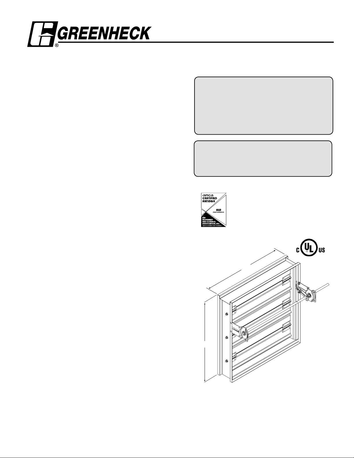
Model SSSMD-201
H*
W*
R
Smoke Dampers
Stainless Steel 3V Blade
UL 555S Leakage Class I
Application
Model SSSMD-201 is a 304 stainless steel leakage rated smoke
damper with 3V style blades. The SSSMD-201 has been qualified to
2000 fpm (10.2 m/s) and 4 in. wg (1 kPa) for operational closure in
emergency smoke control situations. Model SSSMD-201 may be
installed vertically (with blades running horizontally) or horizontally
and is rated for airflow and leakage in either direction.
Ratings
Leakage Class: l
Pressure: 4 in. wg (1 kPa) - differential
pressure
Velocity: Operational rated to 2000 fpm
(10.2 m/s)
Temperature: 350°F (177ºC) with all actuators.
Higher temperature ratings with
some actuators.
Standard Construction
Frame: 5 in. x 1 in. (127mm x 25mm) 16 ga.
(1.5mm) 304 stainless steel hat
channel with reinforced corners. A
low profile head and sill are used on
sizes less than 17 in. (432mm) high
to maximize free area and
performance.
Blades: 16 ga. (1.5mm) 304 stainless steel,
reinforced with 3 longitudinal
structurally designed vee’s.
Seals: Flexible 304 stainless steel jamb
seals.
Linkage: 304 stainless steel - concealed in
jamb.
Axles:
steel.
Bearings: 304 stainless steel sleeve type.
1
/2 in. (13mm) dia. 304 stainless
Model SSSMD-201 meets the requirements for smoke
dampers established by:
National Fire Protection Association
NFPA Standards 92A, 92B, 101 & 105
IBC International Building Codes
New York City (MEA listing #260-91-M)
CSFM California State Fire Marshal
Leakage (Smoke) Damper Listing (#3230-0981:104)
“UL CLASSIFIED (see complete marking on
product)”
“UL CLASSIFIED to Canadian safety standards
(see complete marking on product)”
Standard 555S (Listing #R13317)
Greenheck Fan Corporation certifies that the model
SSSMD-201 shown herein is licensed to bear
the AMCA Seal. The ratings shown are based on
tests and procedures performed in accordance
with AMCA Publication 511 and comply with the
requirements of the AMCA Certified Ratings Programs. The AMCA Certified Ratings Seal applies to
air performance ratings only.
Size Limitations
Minimum Size:
(203mm W x 152mm H)
Maximum Size:
Single Section - 32 in. W x 50 in. H
(813mm W x 1270mm H)
36 in. W x 48 in. H
(914mm W x 1219mm H)
Multiple Section - 144 in. W x 100 in. H
(3658mm W x 2438mm H)
288 in. W x 50 in. H
(7315 mm W x 1270mm H)
8 in. W x 6 in. H
RH
Optional Features
• OCI (Open closed indication switches)
• Electric or pneumatic actuators to accomplish smoke
management and system functions.
• Fail open
Installation instructions available at www.greenheck.com
LH
*W&H dimensions furnished approximately 1/4 in. (6mm) undersize.
(Add sleeve thickness for overall sleeved damper dimension)
Right hand drive is shown. Left hand drive is available upon request.
Page 2
Pressure Drop Data SSSMD-201
5D 6D
5D
D
4 (W) (H
)
3.14
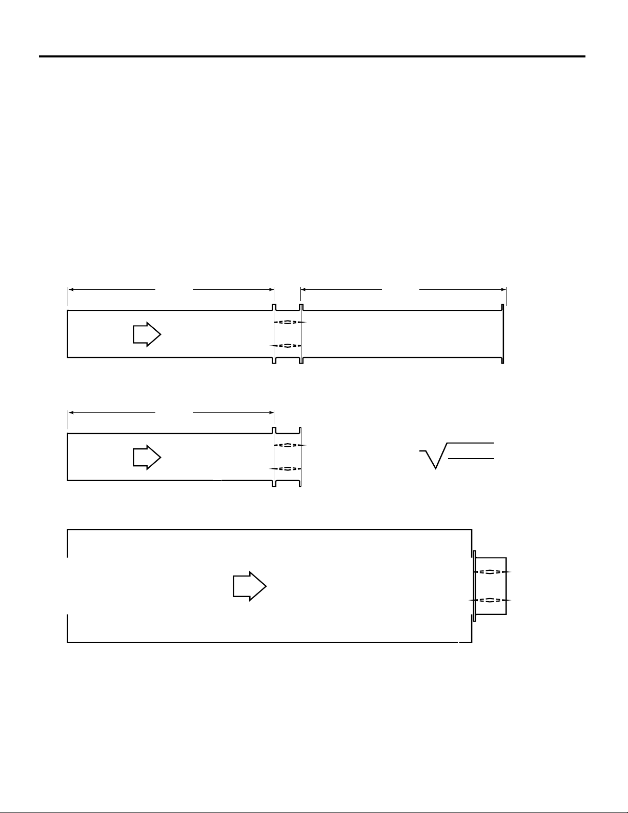
This pressure drop testing was conducted in accordance with AMCA Standard 500-D using the three configurations shown. All
data has been corrected to represent standard air at a density of .075 lb/ft
Actual pressure drop found in any HVAC system is a combination of many factors. This pressure drop information along with an
analysis of other system influences should be used to estimate actual pressure losses for a damper installed in a given HVAC
system.
AMCA Test Figures
Figure 5.3 Illustrates a fully ducted damper. This configuration has the lowest pressure drop of the three test configurations
because entrance and exit losses are minimized by straight duct runs upstream and downstream of the damper.
Figure 5.2 Illustrates a ducted damper exhausting air into an open area. This configuration has a lower pressure drop than
Figure 5.5 because entrance losses are minimized by a straight duct run upstream of the damper.
Figure 5.5 Illustrates a plenum mounted damper. This configuration has the highest pressure drop because of extremely high
entrance and exit losses due to the sudden changes of area in the system.
3
(1.201 kg/m3).
Page 3
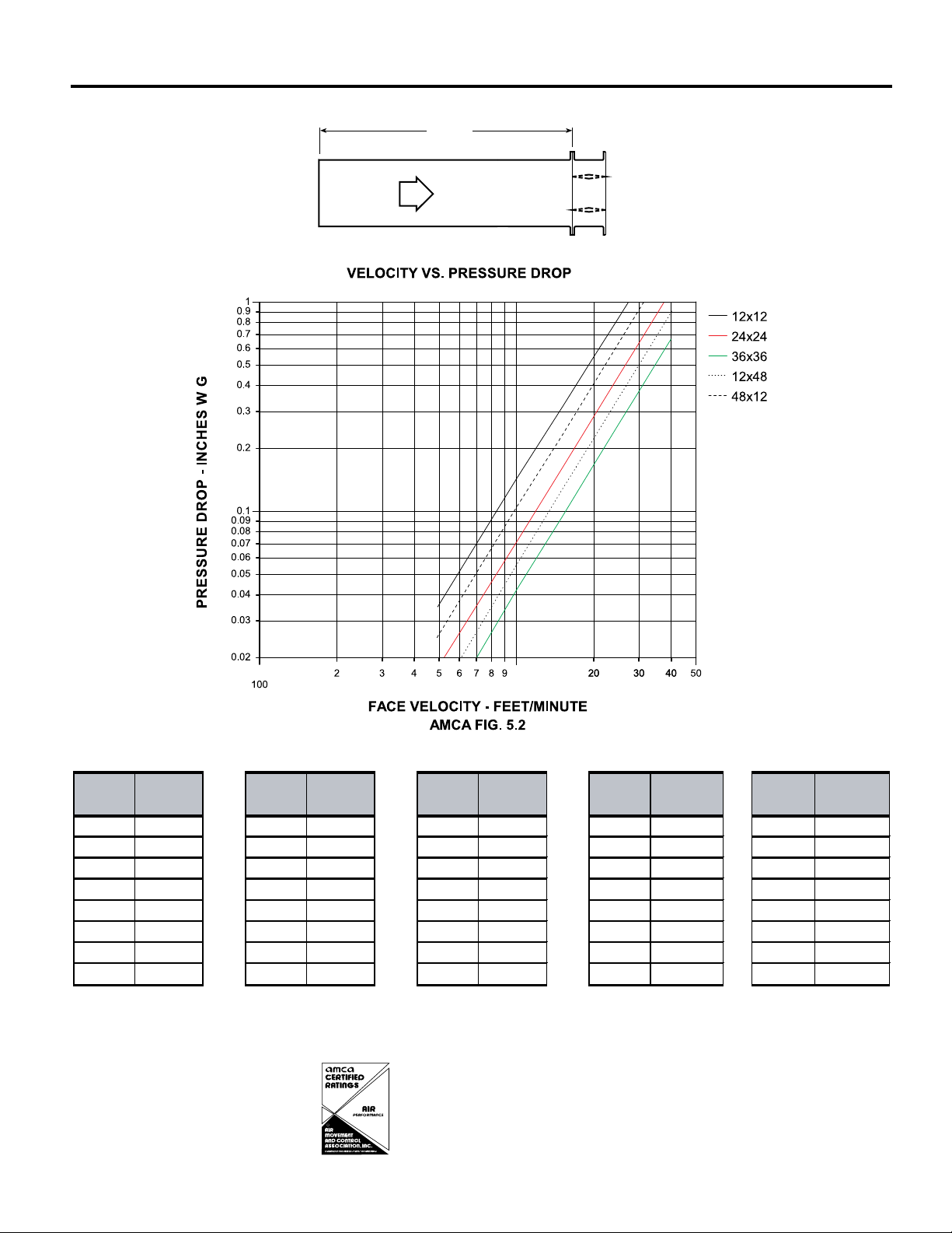
AMCA 5.2 Pressure Drop SSSMD-201
5D 6D
5D
D
=
4 (W) (H )
3.14
Figure 5.3
Figure 5.2
R
Velocity (fpm)
Pressure Drop
(in. wg)
Velocity (fpm)
Pressure Drop
(in. wg)
Velocity (fpm)
Pressure Drop
(in. wg)
Velocity (fpm)
Pressure Drop
(in. wg)
500 0.04 500 0.02 500 0.01 5000.01
1000 0.14 10000.07 10000.04 1000 0.06
15000.31 15000.16 15000.09 1500 0.13
2000 0.55 20000.29 20000.1620000.23
2500 0.86 25000.45 25000.2525000.36
30001.24 30000.65 30000.3630000.52
3500 1.69 3500 0.89 3500 0.49 3500 0.70
4000 2.20 4000 1.16 4000 0.64 4000 0.92
12 in. x 12 in. (305mm x 305mm)
24 in. x 24 in. (610mm x 610mm)
36 in. x 36 in. (914mm x 914mm)
12 in. x 48 in. (305mm x 1219mm)
Velocity (fpm)
Pressure Drop
(in. wg)
5000.03
1000 0.10
1500 0.23
2000 0.41
2500 0.63
3000 0.91
3500 1.24
4000 1.62
48 in. x 12 in. (1219mm x 305mm)
Greenheck Fan Corporation certifies that the model
SSSMD-201 shown herein is licensed to bear
the AMCA Seal. The ratings shown are based on
tests and procedures performed in accordance
with AMCA Publication 511 and comply with
the requirements of the AMCA Certified Ratings
Programs. The AMCA Certified Ratings Seal
applies to air performance ratings only.
Page 4
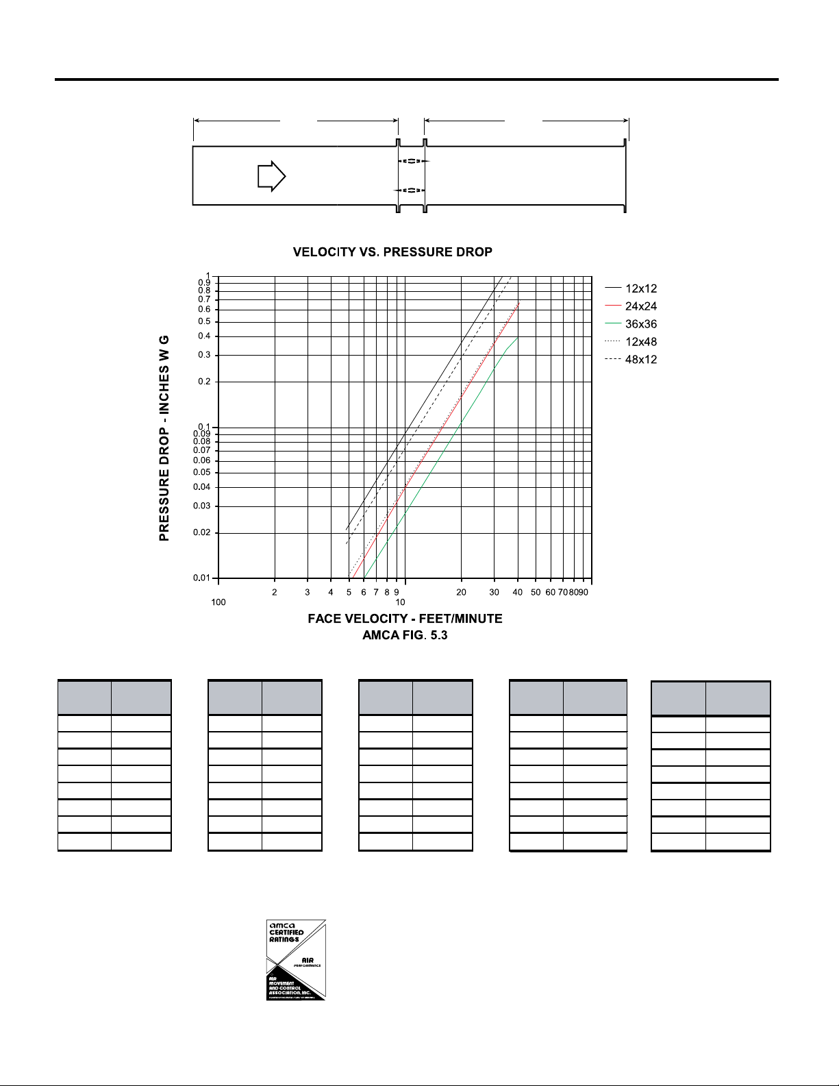
AMCA 5.3 Pressure Drop SSSMD-201
5D 6D
Figure 5.3
Velocity (fpm)
Pressure Drop
(in. wg)
Velocity (fpm)
Pressure Drop
(in. wg)
Velocity (fpm)
Pressure Drop
(in. wg)
Velocity (fpm)
Pressure Drop
(in. wg)
500 0.02 500 0.01 5000.01 5000.01
10000.09 10000.04 1000 0.03 1000 0.04
15000.20 1500 0.09 1500 0.06 1500 0.10
20000.36 20000.16 2000 0.11 2000 0.17
25000.56 2500 0.25 2500 0.17 2500 0.27
30000.81 30000.3530000.24 3000 0.39
3500 1.10 3500 0.48 3500 0.33 3500 0.53
40001.44 40000.63 4000 0.42 4000 0.70
12 in. x 12 in. (305mm x 305mm)
24 in. x 24 in. (610mm x 610mm)
36 in. x 36 in. (914mm x 914mm)
12 in. x 48 in. (305mm x 1219mm)
Velocity (fpm)
Pressure Drop
(in. wg)
500 0.02
1000 0.07
1500 0.16
2000 0.29
2500 0.45
3000 0.64
3500 0.88
4000 1.14
48 in. x 12 in. (1219mm x 305mm)
R
Greenheck Fan Corporation certifies that the model
SSSMD-201 shown herein is licensed to bear
the AMCA Seal. The ratings shown are based on
tests and procedures performed in accordance
with AMCA Publication 511 and comply with
the requirements of the AMCA Certified Ratings
Programs. The AMCA Certified Ratings Seal
applies to air performance ratings only.
Page 5
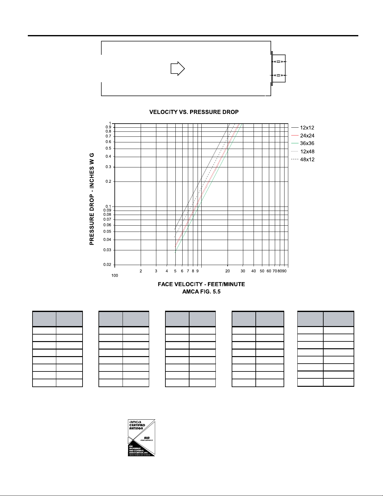
AMCA 5.5 Pressure Drop SSSMD-201
R
5D 6D
5D
D
4 (W) (H)
3.14
Velocity (fpm)
Pressure Drop
(in. wg)
Velocity (fpm)
Pressure Drop
(in. wg)
Velocity (fpm)
Pressure Drop
(in. wg)
Velocity (fpm)
Pressure Drop
(in. wg)
5000.06500 0.03 5000.03 500 0.03
1000 0.22 1000 0.14 1000 0.12 1000 0.13
1500 0.50 1500 0.31 1500 0.26 1500 0.30
2000 0.89 2000 0.54 2000 0.46 2000 0.53
2500 1.39 2500 0.85 2500 0.73 2500 0.83
3000 2.00 3000 1.22 3000 1.05 3000 1.19
3500 2.72 3500 1.66 3500 1.42 3500 1.62
4000 3.55 4000 2.17 4000 1.86 4000 2.11
12 in. x 12 in. (305mm x 305mm)
24 in. x 24 in. (610mm x 610mm)
36 in. x 36 in. (914mm x 914mm)
12 in. x 48 in. (305mm x 1219mm)
Velocity (fpm)
Pressure Drop
(in. wg)
5000.04
1000 0.17
1500 0.38
2000 0.67
2500 1.04
3000 1.50
3500 2.05
4000 2.67
48 in. x 12 in. (1219mm x 305mm)
Greenheck Fan Corporation certifies that the model
SSSMD-201 shown herein is licensed to bear
the AMCA Seal. The ratings shown are based on
tests and procedures performed in accordance
with AMCA Publication 511 and comply with
the requirements of the AMCA Certified Ratings
Programs. The AMCA Certified Ratings Seal
applies to air performance ratings only.
Page 6
5 3 / 8 in.
5 in.
Right hand drive is show n
Left hand drive available upon re quest
LH RH
A
Sleeve Length
V aries
6 in.
3 3 / 4
1 1 / 2 in.
max.
B*
S
T*
in.
A
127mm.
305mm
*
152mm .
127mm
A
Sleeve Length
Varies
38mm max
95mm
3
137mm
127mm
A
Sleeve Length
Varies
38mm max
95mm
3
137mm
Application Data
Damper Sideplate and Sleeve Dimensional Data
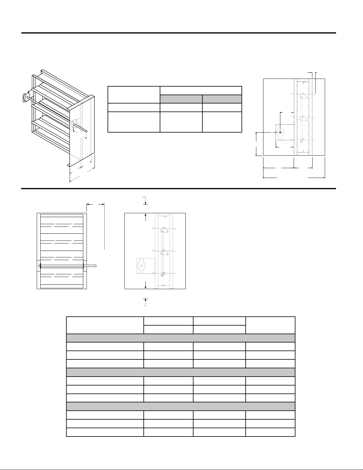
The drawings below illustrate the factory standard sideplate and sleeve mountings for the SSSMD-201. The standard "A"
dimensions listed in the table provide adequate space for the mounting of actuators and controls.
If space constraints are a problem the "A" dimension can be varied between 5 3⁄8 in. (136mm) and 12 in. (305mm).
Sideplate
Sleeve
in. (mm)
"A" Dimension
Standard Maximum
All Dampers* 7 3/16 in. (183) 12 (305)
When Height is
12 (305) 12 (305)
11 in. (279) or less
with OCI
*With the exception of dampers 10 in. high (254mm) or less.
NOTE: Entire damper frame is not required to be installed
within the wall.
Space Envelopes Required for
Actuators and Accessories
Externally mounted actuators always require space outside
of the damper sideplate or sleeve. The “S” dimension
illustrates the clearance required for various available
actuators.
On dampers less than 18 in. (457mm) high, actuators
may also require clearances above and/or below the
sideplate or sleeve. “B” and “T” dimensions are worst case
clearance requirements for some dampers less than 18
in. (457mm) high. All damper sizes under 18 in. (457mm)
high do not require these worst case clearances. If space
availability above or below the damper sleeve is limited,
each damper size should be individually evaluated.
Actuator
Type/Model
B* T* S
With OCI With OCI
120 Volt AC
ML4XXX Series Honeywell 5 1/4 in. (133mm) 3/4 in. (19mm) 6 in. (152mm)
MS4XXX Series Honeywell 6 in. (152mm) 3/8 in. (10mm) 6 in. (152mm)
MS4120 Series Honeywell 6 in. (152mm) 3/8 in. (10mm) 6 in. (152mm)
24 Volt AC
ML8XXX Series Honeywell 5 1/4 in. (133mm) 3/4 in. (19mm) 6 in. (152mm)
MS8XXX Series Honeywell 6 in. (152mm) 3/8 in. (10mm) 6 in. (152mm)
MS8120 Series Honeywell 6 in. (152mm) 3/8 in. (10mm) 6 in. (152mm)
Pneumatic (psi)
331-4551 Siemens 1 in. (25mm) 6 1/4 in. (159mm) 6 1/2 in. (165mm)
331-2976 Siemens 2 3/8 in. (60mm) 12 1/8 in. (308mm) 9 1/4 in. (235mm)
MK2-7121 Invensys 3 3/4 in. (95mm) 16 1/2 in. (419mm) 10 in. (254mm)
* For dampers 18 in. (457mm) or more in height these dimensions are 0 in. .
Page 7
50 in.
32 in. (813mm)
32 in. (813mm)
64 in. (1626mm)
50 in.
(1270mm)
32 in. (813mm)
(1270mm)
50 in.
(1270mm)
D* +
2 in. (51mm) +T
s
D*
TYPE R
16 in. (406mm)
Min.
2 1 / 8 in.
D* + 2 in. (51mm)+T
s
TYPE O
W
*
H*
W*
+ 2 in. (51mm)+T
s
H* + 2 in. (51mm)+T
s
W*
H*
TYPE C
H* + 2 in. (51mm)+T
s
(54mm)
16 in. (406mm)
Min.
2 1 /8 in.
(54mm)
16 in. (406mm)
Min.
W* + 2 in. (51mm)+T
s
(54mm)
2 1 / 8 in.
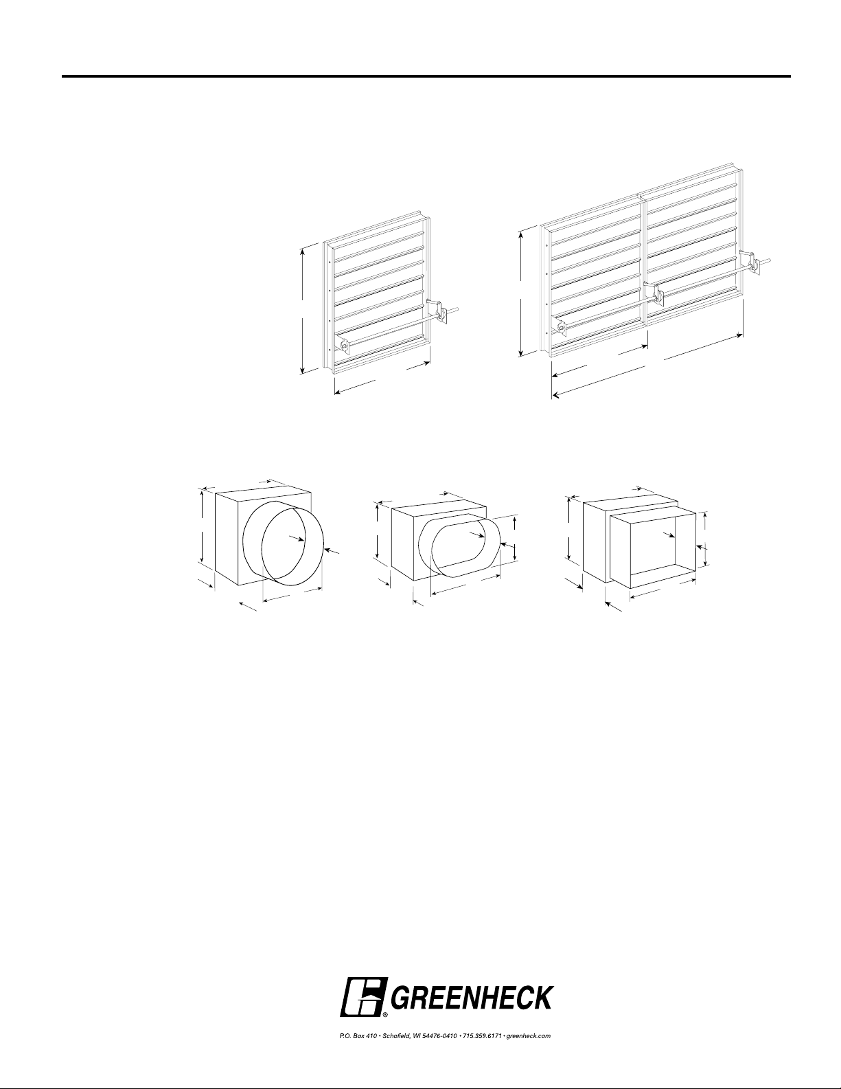
Damper Sizing Information
Damper Sizing
Information
Dampers larger than maximum single section size are supplied as a factory assembly of two or
more sections of equal size.
The following figures show damper sections and assemblies that have been qualified for operation
with a single actuator. Larger sizes can be accommodated using multiples of these assembles.
Transitioned Damper
Dimensions
Single Section Multi Section
When a fire/smoke damper is being used in conjunction with round or oval ductwork, the
SSSMD-201 can be supplied in a factory sleeve with round or oval transitions on both ends of
the sleeve. Dampers should be ordered to the duct dimensions. Drawings below show overall
damper size.
These dimensions are furnished approximately 1/4 in. (6mm) undersize, except round and oval dimensions which are approximately 1/8 in. (3mm) undersize.
*
Ts = (2)(Sleeve Thickness)
Specifications
Smoke Dampers meeting the following specifications shall be
furnished and installed where shown on plans and/or as described
in schedules. Dampers shall meet the requirements of NFPA 92A,
92B, 101 and 105 and further shall be tested, rated and labeled in
accordance with the latest edition of UL Standards 555S. Dampers
shall be UL labeled for use in dynamic systems.
Dampers shall have a UL555S leakage rating of Class I and a
temperature rating of 250ºF (121ºC) minimum. Dampers shall have a
UL555S operational airflow rating equal to or greater than the airflow
at its installed location and an operational pressure rating of 4 in. wg
(1 kPa). Damper actuators shall be factory mounted and qualified for
use with the damper in accordance with UL555S. Damper actuators
shall be (specifier select one of the following) electric type for 120V,
24V, 230 volt operation or pneumatic type for 25 psi minimum (30 psi
maximum) operation. Manufacturer’s submittal data shall indicate
actuator space requirements around the damper.
Damper blades shall be 16 ga. (1.5mm) 304 stainless steel 3V type
with three longitudinal grooves for reinforcement. Blades shall be
completely symmetrical relative to their axle pivot point, presenting
identical resistance to airflow and operation in either direction
through the damper (blades that are non-symmetrical relative to
their axle pivot point or utilize blade stops larger than 0.5 in. are
unacceptable).
Damper frames shall be 16 ga. (1.5mm) 304 stainless steel formed
into a structural hat channel shape with reinforced corners. Bearings
shall be stainless steel type rotating in extruded holes in the damper
frame. Jamb seals shall be stainless steel compression type.
The Damper manufacturer’s submittal data shall certify all air
performance pressure drop data is licensed in accordance with the
AMCA certified ratings program for test figures 5.2, 5.3, and 5.5.
Damper air performance shall be developed in accordance with the
latest edition of AMCA Standard 500-D.
The basis of design is Greenheck’s model SSSMD-201.
Copyright ©2006 Greenheck Fan Corporation
SSSMD-201 Rev 5 July 2006
 Loading...